Transcription
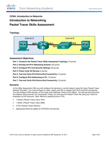
CCNA: Introduction to NetworksIntroduction to NetworkingPacket Tracer Skills Assessment.TopologyAssessment ObjectivesPart 1: Construct the Packet Tracer Skills Assessment Topology (15 points)Part 2: Develop the IPv4 Addressing Scheme (25 points)Part 3: Configure IPv4 and Security Settings (25 points)Part 4: Power Cycle All Devices (5 points)Part 5: Test and Verify IPv4 End-to-End Connectivity (10 points)Part 6: Configure IPv6 Addressing on R1 (10 points)Part 7: Test and Verify IPv6 End-to-End Connectivity (10 points)ScenarioIn this Skills Assessment (SA) you will configure the devices in a small network using the Cisco Packet TracerNetwork Simulator. You must configure a router, switch and PCs to support both IPv4 and IPv6 connectivity.You will configure SSH security, on the router and traditional Telnet on the Switch. You will test and documentthe network using common CLI commands. Finally, you will save the Packet Tracer file using your name forevaluation by the instructor. Note: Minimum passing score is 70%. 1 Router (Packet Tracer Cisco 1941) 1 Switch (Packet Tracer Cisco 2960) 2 PCs (Packet Tracer Generic) Appropriate Ethernet cables for DTE/DCE Connectivity 2014 Cisco and/or its affiliates. All rights reserved. Modified by RBP September 19, 2014Page 1 of 8
CCNA: Introduction to NetworksPart 1: Construct the Packet Tracer SA Topology (15 points)Step 1: Use the information from the assessment scenario to construct the problem topologyin Packet Tracer and connect with the appropriate cables.Step 2: Legibly document and label the topology in this and all succeeding steps withsufficient detail to troubleshoot and test the topology. This documentation may bedone directly in Packet Tracer or on hardcopy paper.Part 2: Develop the IPv4 Addressing Scheme (25 points)Step 1: Given an IP address and mask of 192.168.0.0/24, design an IP addressing scheme thatsatisfies the following requirementsSubnetNumber of DevicesSubnet A (subnet 0)30Subnet B126Step 2: Use the 0th subnet (subnet zero) for Subnet A. Document the appropriate informationon the topology drawing or directly with in Packet Tracer and on this page.Subnet ASpecificationStudent InputNumber of 1 bits in the network maskIP mask (binary)IP mask (dotted decimal)Number of usable hostsIP Network/MaskFirst IP Host addressLast IP Host addressStep 3: Use the next available address block for Subnet B.CCNA: Introduction to Networks Packet Tracer Skills AssessmentPage 2 of 8
CCNA: Introduction to NetworksSubnet BSpecificationStudent InputNumber of 1 bits in the network maskIP mask (binary)IP mask (dotted decimal)Number of usable hostsIP Network/MaskFirst IP Host addressLast IP Host addressHost computers will use the first IP host address in the subnet. The network router will use the LASTnetwork host address. The switch will use the second to the last network host address.Write down the IP address information for each device:DeviceIP addressSubnet MaskGatewayPC-AR1-G0/0N/AR1-G0/1N/AS1 (VLAN1)PC-BPart 3: Configure IPv4 and Security Settings (25 points)Step 1: Configure host computers.After configuring each host computer, Verify and record the host network settings with the ipconfig /allcommand.PC-A Network ConfigurationDescriptionPhysical AddressIP AddressSubnet MaskDefault GatewayCCNA: Introduction to Networks Packet Tracer Skills AssessmentPage 3 of 8
CCNA: Introduction to NetworksPC-B Network ConfigurationDescriptionPhysical AddressIP AddressSubnet MaskDefault GatewayStep 2: Configure R1 – Configuration Tasks for R1. Include the Following:NOTE: Configure R1 remote login for use with an ssh terminal only.TaskSpecificationDisable DNS lookupRouter nameR1Domain nameccna-lab.comEncrypted privileged exec passwordciscoenpassConsole access passwordciscoconpassCreate an ssh administrative user in the localdatabaseUsername: adminPassword: admin1passSet login on VTY lines to use local databaseSet VTY lines to accept an ssh connection only“Unauthorized Access Prohibited”Encrypt the clear text passwordsMOTD BannerInterface G0/0Set the Layer 3 IPv4 addressActivate InterfaceInterface G0/1Set the Layer 3 IPv4 addressActivate InterfaceGenerate a RSA crypto key1024 bits modulusCCNA: Introduction to Networks Packet Tracer Skills AssessmentPage 4 of 8
CCNA: Introduction to NetworksStep 3: Configure S1- Configuration Task for S1 Include the following:NOTE: Configure S1 remote login for use with a telnet terminal only.TaskSpecificationSwitch nameS1Configure Management Interface (SVI)Set Default GatewaySet the Layer 3 IPv4 address/maskActivate InterfaceEncrypted privileged exec passwordciscoenpassConsole access passwordciscoconpassTelnet access passwordciscovtypassStep 4: Backup the R1 router and S1 switch configurations.Part 4:Power Cycle All Devices (5 points)Step 1: Initialize the router and switch.Within Packet Tracer, click the ‘Power Cycle Devices’ function.Step 2: Verify router and switch configurationsVerify that the router and switch are operational after restarting.Part 5: Test and Verify IPv4 End-to-End Connectivity (10 points)Step 1: Verify network connectivity.Use the ping command to test connectivity between all network devices.Use the following table to methodically verify connectivity with each network device. Take corrective action toestablish connectivity if a test fails:CCNA: Introduction to Networks Packet Tracer Skills AssessmentPage 5 of 8
CCNA: Introduction to NetworksFromToPC-AR1, G0/0PC-AR1, G0/1PC-AS1 VLAN 1PC-APC-BPC-BR1, G0/1PC-BR1, G0/0PC-BS1 VLAN 1IP AddressPing ResultsPart 6: Configure IPv6 Addressing on R1 (10 points)Given an IPv6 network address of 2001:DB8:ACAD::/48, configure IPv6 addresses for the Gigabit interfaceson R1. Use FE80::1 as the link-local address on both interfaces.Note: This will allow the PCs to obtain their IP address and default gateway information automatically usingStateless Address Autoconfiguration (SLAAC).Step 1: Configure R1.Configuration tasks for R1 include the following:TaskSpecificationConfigure G0/0 to use the first address in subnet A.Assign the IPv6 unicast addressAssign the IPv6 link-local addressConfigure G0/1 to use the first address in subnet B.Assign the IPv6 unicast addressAssign the IPv6 link-local addressEnable IPv6 unicast routing.CCNA: Introduction to Networks Packet Tracer Skills AssessmentPage 6 of 8
CCNA: Introduction to NetworksPart 7: Test and Verify IPv6 End-to-End Connectivity (10 points)Step 1: Obtain the IPv6 address assigned to host PCs.PC-A IPv6 Network ConfigurationDescription In PC-A workstation configuration selectthe Auto Config button to display theaddress Record IPv6 Address/MaskAnswers may vary but will start with:2001:DB8:ACAD:A:x:x:x:xNOTE: PC-A is in subnet ‘A’Auto Config to FE80::1Default GatewayPC-B IPv6 Network ConfigurationDescription In PC-B workstationconfiguration select theAuto Config button todisplay the addressAnswers may vary but will start with:2001:DB8:ACAD:B:x:x:x:xNOTE: PC-B is in subnet ‘B’Record IPv6 Address/MaskIPv6 Default GatewayAuto Config to FE80::1Step 2: Use the ping command to verify network connectivity.IPv6 network connectivity can be verified with the ping command. Use the following table to methodicallyverify connectivity with each network device. Take corrective action to establish connectivity if a test fails:CCNA: Introduction to Networks Packet Tracer Skills AssessmentPage 7 of 8
CCNA: Introduction to NetworksFromToPC-AR1, G0/0PC-AR1, G0/1PC-APC-BPC-BR1, G0/1PC-BR1, G0/0IP AddressCCNA: Introduction to Networks Packet Tracer Skills AssessmentPing ResultsPage 8 of 8
CCNA: Introduction to Networks Packet Tracer Skills Assessment Page 2 of 8 Part 1: Construct the Packet Tracer SA Topology (15 points) Step 1: Use the information from the assessment scenario to construct the problem topology in Packet Tracer and connect with the appropriate cables.