Transcription
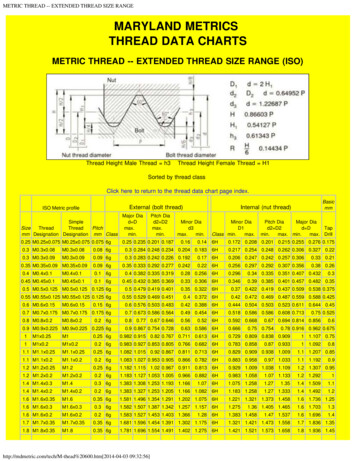
1THREADGAGINGREFERENCEGUIDEDistributed by:GageWorldwideIncTHE CribL. S.STARRETTCOMPANY6701Old 28th StStreetSE, SuiteB MA 01331121 Crescent Athol,GrandRapids,MI 49546-6937Telephone (508)249-3551 USAPhone:001.616.954.6581Fax (508)249-8495Web: www.gagecrib.comKnow your threads, inside-out.
3Table of ContentsSECTION 1:Fundamentals of Screw Thread Technology . 4 - 7SECTION 2:Definitions and Terminology . 8 - 11SECTION 3:Gage Design Contacts . 12 - 13SECTION 4:Technical Considerations . 14 - 23SECTION 5:Plating, Metric and RFQ . 24 - 27Distributed by:Gage Crib Worldwide Inc6701 Old 28th St SE, Suite BGrand Rapids, MI 49546-6937 USAPhone: 001.616.954.6581Web: www.gagecrib.com
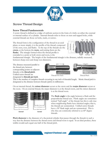
4FUNDAMENTALS OF SCREW THREAD TECHNOLOGYScrew Thread DesignationEXAMPLE: .3125 - 24 UNJF - 3A (B).3125 Nominal Diameter Maximum Major Diameter24 Number of threads per inchUN Unified National (60 – V-thread)J Controlled root radius — High Strength(Minor diameter increased from UN to UNJ.)F Fine thread series3 Thread classA External threadB Internal threadScrew Thread AssemblyDistributed by:Gage Crib Worldwide Inc6701 Old 28th St SE, Suite BGrand Rapids, MI 49546-6937 USAPhone: 001.616.954.6581Web: www.gagecrib.com
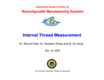
5SECTION 1Functional Diameter SizePitch Diameter Size Variations of Thread Elements and Characteristics Functional Diameter SizeThe Functional diametersize is the Pitch diameter size plus the cumulative effect of variationsin lead, (including uniformity of helix) flankangle, taper, and roundness. The Functionalsize is the measuredvalue of the maximummaterial size of either aproduct internal orexternal screw thread. ThreadFormVariationÚ ÙFSPDÚ Pitch Diameter SizeThe Pitch diameter sizeis defined as the diameter of a cylinder thatpasses through thethread profile of either aproduct internal orexternal screw thread tomake the widths ofthread ridge and threadgroove equal on bothsides of the thread. ThePitch diameter is themeasured value of theminimum material limitof size of either a product internal or externalscrew thread.Width of Thread Ridge Width of Thread GrooveTHREAD RIDGE àßPDÚ Distributed by: Gage Crib Worldwide Inc6701 Old 28th St SE, Suite BGrand Rapids, MI 49546-6937 USAPhone: 001.616.954.6581 Web: www.gagecrib.com THREAD GROOVEß à
6FUNDAMENTALS OF SCREW THREAD TECHNOLOGYReference Federal Standard H28/20 Systems of Gagingt 5.1.3. SYSTEM 2121. GO/NO GO GAGING5.1.3.1. System 21 provides for interchangeable assembly withfunctional size control at the maximum material limits within the length of standard gaging elements;and also control of character-istics identified as NOT-GO functional diameters or as HI (Internal)and LO (External) functional diameters. These functional gages provide some control at the minimum material limit when there is little variation in thread form characteristics such as lead, flankangle, taper and roundness.t 5.1.4 SYSTEM 2222. VARIABLES INDICATING TYPE GAGING5.1.4.1. System 22 provides for interchangeable assembly withfunctional size control at the maximum material limits within the length of standard gaging elements;and also control of the minimum material size limits over the length of the full thread. Other threadcharacteristics such as lead, flank angle, taper and roundness variations are confined within theselimits with no specific control of their magnitudes. For UNJ and MJ external threads, control is alsoprovided for the thread root radius and rounded root minor diameter.t 5.1.5 SYSTEM 23. SAFETY CRITICALt 5.2 ACCEPTABILITY.Screw thread acceptability criteria are in accordance with Section 6 of ASME B1.3M-1992. Alsosee subsection 5.7.Other Reference Standardst ASME B1.1 Unified Inch Screw Threads.t ASME B1.2 Gages and Gaging for Unified Inch Screw Threads.t ASME B1.3M Screw Thread Gaging Systems for Dimensional Acceptability – Inch and MetricThreads (UN, UNR, UNJ, M and MJ).Distributed by:Gage Crib Worldwide Inc6701 Old 28th St SE, Suite BGrand Rapids, MI 49546-6937 USAPhone: 001.616.954.6581Web: www.gagecrib.com
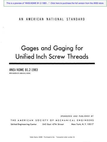
7SECTION 1Thread ClassMAXIMUM P.D.TOLERANCE.225 .250 - 20 UNC - ASS2B CLASS3B.219MAXIMUM P.D.TOLERANCE NOALLOWANCEALLOWANCE MINIMUM P.D.TOLERANCE .217b.215.213CLASS2ACLASS1A }CLASS3ABASICSIZE TOLERANCE.211THREADCLASSTOLERANCEOVERLAP .209MINIMUM P.D.TOLERANCEClasses of threads are differentiated by the amount of tolerance andallowance specified. Indicating gaging is typically mastered at maximummaterial condition. This is the minimum Pitch diameter tolerance limit forI.D. threads and the maximum Pitch diameters tolerance limit for O.D.threads.Distributed by:Gage Crib Worldwide Inc6701 Old 28th St SE, Suite BGrand Rapids, MI 49546-6937 USAPhone: 001.616.954.6581Web: www.gagecrib.com
8DEFINITIONS AND TERMINOLOGYFIGURE 1Screw ThreadThe Screw Thread is a ridge, usually ofuniform section and produced by forming a groove as a helix on the externalor internal surface of a cylinder, or as aconical spiral on the external or internalsurface of a cone. A screw threadformed on a cylinder is known as astraight or parallel thread, to distinguishit from a tapered thread that is formedon a cone.FIGURE 2ThreadA thread is a portion of a screw threadencompassed by one ridge wrappedaround a cylinder or cone for one complete turn.Single Start ThreadA single start thread is one having oneridge wrapped around a cylinder orcone for the total length.FIGURE 3Multiple-Start ThreadA multiple-start thread is one that hastwo or more ridges wrapped around acylinder or cone for the total length.External ThreadAn external thread is on a cylindrical orconical external surface (referenceFigures 1, 2 and 3).Distributed by: Gage Crib Worldwide Inc6701 Old 28th St SE, Suite BGrand Rapids, MI 49546-6937 USAPhone: 001.616.954.6581 Web: www.gagecrib.com
9SECTION 2FIGURE 4Internal ThreadAn internal thread is on a cylindrical orconical internal surface.FIGURE 5FIGURE 6Right-Hand ThreadLeft-Hand ThreadA thread is a righthand thread if, whenviewed axially, it windsin a clockwise andreceding direction. Athread is consideredright-hand unlessspecifically shownotherwise.A thread is a left-handthread if, when viewedaxially, it winds in acounterclockwise andreceding direction. Allleft-hand threads aredesignated LH.FIGURE 7Flank of ThreadThe flank (or side) of the ridge. The flank surface intersection with an axial plane is theoretically a straightline.Crest of ThreadThe crest is that surface of the thread that joins theflank of the thread and is farthest from the cylinder orcone from which the thread projects.Root of ThreadThe root is that surface of the thread that joins theflanks of adjacent thread forms and is identical with orimmediately next to the cylinder or cone from which thethread projects.Distributed by: Gage Crib Worldwide Inc6701 Old 28th St SE, Suite BGrand Rapids, MI 49546-6937 USAPhone: 001.616.954.6581 Web: www.gagecrib.com
10DEFINITIONS AND TERMINOLOGYMaximum Material ConditionThe condition where the product screw thread contains the maximum amountof material.Definitions&TerminologyMinimum Material ConditionThe condition where the product screw thread contains the minimum amount ofmaterial.ToleranceThe total amount of variation permitted for the size of a dimension. It is thedifference between the maximum limit of size and the minimum limit of size fora given thread size.AllowanceThe difference between the design (maximum material) size and the basic size.Basic SizeThe basic size is that size from which the limits of size are derived by theapplication of allowances and tolerances.Design SizeThe design size is the basic size with allowance applied, from which the limitsof size are derived by the application of tolerance. If there is no allowance, thedesign size is the same as the basic size.Nominal SizeThe nominal size is the designation that is used for general identifical of thediameter.Thread seriesThread series are groups of diameters/pitch combinations distinguished fromeach other by the number of threads per inch applied to specific diameters.Classes of ThreadClasses of threads are distinguished from each other by the amount of tolerance or tolerance and allowance specified.Distributed by: Gage Crib Worldwide Inc6701 Old 28th St SE, Suite BGrand Rapids, MI 49546-6937 USAPhone: 001.616.954.6581 Web: www.gagecrib.com
11SECTION 2PitchDefinitions&TerminologyPitch is not pitch diameter, threads per inch (TPI), nor is it LEAD, but it is theaxial distance defined in (x,y) between any point on a thread to the corresponding point on the adjacent thread.Pitch Number of thread startsNumber of threads per inchLeadLead is the axial advance per unit rotation for a given pitch distance. Pitchequals lead when the thread form is ideal.Major CylinderThe major cylinder bounds the crest of an external straight thread or the root ofan internal straight thread.Minor CylinderThe minor cylinder bounds the root of an external straight thread or the crest ofan internal thread.Pitch CylinderThe pitch cylinder is one of such diameter and location of its axis that its surface would pass through a straight thread in such a manner as to make thewidth of the thread ridge and the thread groove equal.Pitch LineThe pitch line is linear and parallel to the center line of the pitch cylinder. Defined where thread ridge and thread groove are equal along the length of thethread.Thread AxisThe thread axis is the axis of its pitch cylinder.Actual SizeAn actual size is a measured size.REFERENCE: ASME B1.7MDistributed by:Gage Crib Worldwide Inc6701 Old 28th St SE, Suite BGrand Rapids, MI 49546-6937 USAPhone: 001.616.954.6581Web: www.gagecrib.com
12GAGE DESIGN CONTACTSUN GAGE PROFILE CONTACTSGage Contact Profile forFunctional Diameter Size MeasurementsFUNCTIONAL DIAMETER SIZEFunctional ContactProduct External ThreadFunctional ContactGage Contact Profile forPitch Diameter Size MeasurementsPITCH DIAMETER SIZEP.D. Vee ContactProduct External ThreadP.D. Cone ContactDistributed by:Gage Crib Worldwide Inc6701 Old 28th St SE, Suite BGrand Rapids, MI 49546-6937 USAPhone: 001.616.954.6581Web: www.gagecrib.com
Distributed by: Gage Crib Worldwide Inc6701 Old 28th St SE, Suite BGrand Rapids, MI 49546-6937 USAPhone: 001.616.954.6581 Web: www.gagecrib.comINTERNAL UN GAGE PROFILE CONTACTSGage Contact Profile forFunctional Diameter Size MeasurementsGage Contact Profile forPitch Diameter Size Measurements13
14SECTION 3 - TECHNICAL CONSIDERATIONSINDICATING THREAD GAGINGGage Contact Designs Pitch Diameter Size –Cone & Vee Rolls (120 ) Functional Diameter Size –Multi-Rib Rolls (120 ) Functional Diameter Size –Full Form Segments (180 )Product Screw Thread Elements & Characteristicsn LEADn Longn Shortn Includes helical deviation"drunk thread"n FLANK ANGLEn Plusn Minusn TAPERn Frontn Backn OUT OF ROUNDn Even loben Odd loben MAJOR DIAMETERn PITCH DIAMETERn MINOR DIAMETERDistributed by:Gage Crib Worldwide Inc6701 Old 28th St SE, Suite BGrand Rapids, MI 49546-6937 USAPhone: 001.616.954.6581Web: www.gagecrib.com
15SECTION 4Anatomy of a UN or UNJ Screw ThreadUNJ —.3125PUNn H Height of the Fundamental Triangle: (Cos 30 / TPI) or (Cos 30 x P)n FLANK ANGLES are made up of the two half angles of 30 each forthe 60 included angle.n MAJOR DIAMETER is at P/8 or 0.125Pn PITCH DIAMETER is at P/2 or 0.500Pn MINOR DIAMETER is at P/4 or 0.250P for UN or UNJ is at 5P/16 or .3125Pn TPI Number of Threads per Inchn N Number of Thread Startsn P PitchP N/TPIDistributed by:Gage Crib Worldwide Inc6701 Old 28th St SE, Suite BGrand Rapids, MI 49546-6937 USAPhone: 001.616.954.6581Web: www.gagecrib.com
16TECHNICAL CONSIDERATIONSVARIATIONS LeadPÙ ÚIdealLead ÚLongLead ÚShortLead ÚDistributed by:Gage Crib Worldwide Inc6701 Old 28th St SE, Suite BGrand Rapids, MI 49546-6937 USAPhone: 001.616.954.6581Web: www.gagecrib.comLead is the axial advance per unit rotation for a given pitch distance.
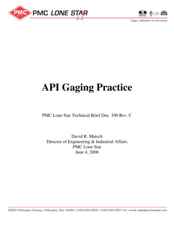
17SECTION 4VARIATIONS Flank AngleA virtual variation in effective diameter also occurs if the flankangledeviates from its specified value.Distributed by:Gage Crib Worldwide Inc6701 Old 28th St SE, Suite BGrand Rapids, MI 49546-6937 USAPhone: 001.616.954.6581Web: www.gagecrib.comFIGURE 12.Virtual Variation ofEffective Diameter dueto Errors in Flank Angle.Reference: Sidders; Guide to World Screw Threads, page 212, Figure 12.
18TECHNICAL CONSIDERATIONSDIFFERENTIAL GAGING TaperÝ123456789011234567890112345678901P.D. Vee 011234567890112345678901Product External 678901ÞP.D. Cone ContactTo measure Taper:Use the Pitch diameter gage (cone and vee) and measure atpositions along the length of thread without rotating the part.Any deviation of the dial indicator needle will tell the directionand magnitude of the tapered condition.Distributed by:Gage Crib Worldwide Inc6701 Old 28th St SE, Suite BGrand Rapids, MI 49546-6937 USAPhone: 001.616.954.6581Web: www.gagecrib.com
19SECTION 4DIFFERENTIAL GAGING Out-of-RoundSegmentRollODD LOBE120 EVEN LOBE180 RollRollSegmentTo measure Out-of-Round:Use the 180 Functional segment to capture the full magnitude of an egg-shaped (even lobe) out-of-round. Use the 120 cone and vee or multi-rib roll contacts for a tri-lobe (odd lobe)out-of-round. When using the Functional diameter gage(multi-rib or segment) rotate the part to observe the largestindicated value for O.D. and the smallest value for I.D. threads.When using the Pitch diameter gage (cone and vee) rotatethe part to observe the smallest indicated value for O.D. andthe largest value for I.D. threads.Distributed by:Gage Crib Worldwide Inc6701 Old
ASME B1.2 ASME B1.2 Π. Gages and Gaging for Unified Inch Screw Threads. t. ASME B1.3M ASME B1.3M Π. Screw Thread Gaging Systems for Dimensional Acceptability РInch and Metric Threads (UN, UNR, UNJ, M and MJ). Distributed by: Gage Crib Worldwide Inc 6701 Old 28th St SE, Suite B Grand Rapids, MI 49546-6937 USA Phone: 001.616.954.6581 Web: www.gagecrib.com . 7. Thread