Transcription
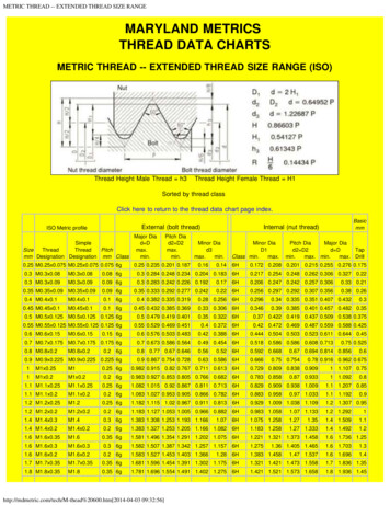
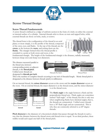
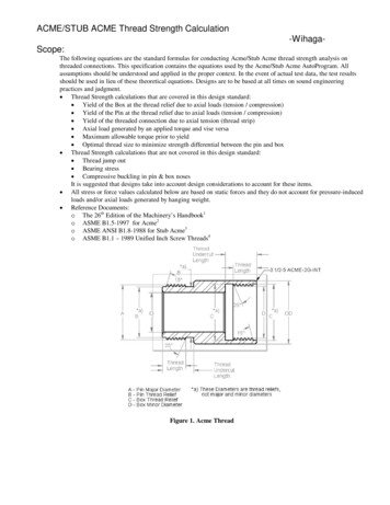
ACME/STUB ACME Thread Strength Calculation-WihagaScope:The following equations are the standard formulas for conducting Acme/Stub Acme thread strength analysis onthreaded connections. This specification contains the equations used by the Acme/Stub Acme AutoProgram. Allassumptions should be understood and applied in the proper context. In the event of actual test data, the test resultsshould be used in lieu of these theoretical equations. Designs are to be based at all times on sound engineeringpractices and judgment. Thread Strength calculations that are covered in this design standard: Yield of the Box at the thread relief due to axial loads (tension / compression) Yield of the Pin at the thread relief due to axial loads (tension / compression) Yield of the threaded connection due to axial tension (thread strip) Axial load generated by an applied torque and vise versa Maximum allowable torque prior to yield Optimal thread size to minimize strength differential between the pin and box Thread Strength calculations that are not covered in this design standard: Thread jump out Bearing stress Compressive buckling in pin & box nosesIt is suggested that designs take into account design considerations to account for these items. All stress or force values calculated below are based on static forces and they do not account for pressure-inducedloads and/or axial loads generated by hanging weight. Reference Documents:o The 26th Edition of the Machinery’s Handbook1o ASME B1.5-1997 for Acme2o ASME ANSI B1.8-1988 for Stub Acme3o ASME B1.1 – 1989 Unified Inch Screw Threads4Figure 1. Acme Thread
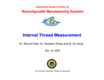
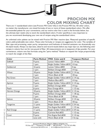
Technical Application: Positive values indicate a tensile load while negative values indicate a compressive load. The designer mustidentify critical compressive buckling loads at the box/pin nose. This functionality is beyond the scope of thisStandard.The Thread Optimization feature in the AutoProgram will allow evaluation of various thread sizes with constantpitches. The designer must keep Design for Manufacturability and Design for Service in mind when choosingthread pitches.Global Assumptionso The material’s mechanical properties are homogeneous and isotropic throughout the cross-section.o The mechanical properties of the material are of equal magnitude in tension and compression.o Cross-sections remain plane under loading conditions.o The materials have ductile characteristics.o Simple axial/shear loading results in a uniform axial/shear stress distribution across a uniform crosssection.o Materials obey Hooke’s Laws of elasticity ( E ).o The minimum yield strength at .2% offset strain, rather than typical (average) yield strength of amaterial, is the basis by which stress at yield is defined.o Shear strength is 50% to 60% of the minimum yield strength. Two existing theories are the DistortionEnergy Theory (0.577 * Ys) and the Maximum Shear Stress Theory (0.5 * Ys).o The selected material will not be used in an environment that will adversely affect its mechanical orphysical properties.o Calculated stresses are based on static loading conditions if appropriate to the application.Design Information:1. Acme /Stub Acme Tensile RatingFigure 2. Thread Reliefs and Maximum/Minimum Material DimensionsThe tensile rating for an Acme/Stub Acme Connection is the maximum value of axial tension that can be applied acrossthe wall thickness without the material yielding. The box (female thread) wall thickness dimension is defined by thedifference between the maximum thread relief ID and minimum OD for the box connection. The pin (male thread) wallthickness dimension is defined by the difference between the minimum thread relief OD and maximum ID for the pinconnection. Figure 2 shows the thread reliefs and the maximum / minimum diameters. However not all Acme/Stub Acme
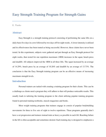
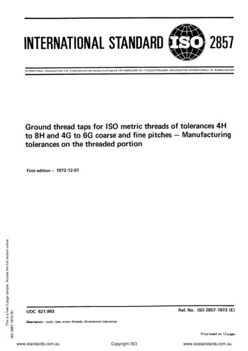
connections have a thread relief after the threads. In this situation the wall thickness is defined by maximum thread rootand minimum OD for the box and minimum thread root and maximum ID for the pin.1.1. FormulasPinTensile BoxTensile PinTensileArea * MinimumYield SafetyFactor(lbf) BoxTensileArea * MinimumYield SafetyFactor(lbf)1.2. Intermediate Equationsπ* MinimumPinThreadRelief 2 MaximumInsideDiameter 2 (in2)4πBoxTensileArea * (MinimumOutsideDiameter 2 MaximumBoxThreadRelief 2 ) (in2)4PinTensileArea 1.3. User Input Variables1.3.1.1.3.2.1.3.3.1.3.4.1.3.5.Maximum Inside Diameter (in)Minimum Outside Diameter (in)Thread Relief (Pin, Box, Min. & Max.) (in)Minimum Yield (psi)Factor of Safety1.4. Output Variables1.4.1.1.4.2.1.4.3.1.4.4.Box Tensile Rating (lbf)Pin Tensile Rating (lbf)Box Tensile Area (in2)Pin Tensile Area (in2)2. Acme/Stub Acme Thread Shear Rating (Thread Stripping)Another common form of thread yielding occurs when the applied axial tension exceeds the maximum allowable threadshear rating. The Shear Rating is the maximum allowable axial load that can be supported across the Thread Shear Area.Thread Shear Area is defined as the total ridge cross-sectional area intersected by a specific cylinder with diameter andlength equal to the mating thread engagement. Usually the cylindrical diameter for external thread shearing is the minordiameter of the internal thread and for the internal thread shearing it is the major diameter of the external thread1 (seeFigure 3). Length of thread engagement of two mating threads is the axial distance over which the two threads, eachhaving full form at both crest and root, are designed to contact1. Since the location of external (pin) thread failure has asmaller diameter than the diameter corresponding to internal (box) thread failure, the connection will fail at the external(pin) thread, assuming that both the pin and box have the same yield strength, etc. Shear (thread stripping) strengths ofscrew threads under load are dependent, in addition, on mating component relative material strengths, connectiongeometry, and coefficient of friction between thread bearing surfaces. Effective shear areas are therefore somewhat lessthan the geometric values calculated below4.
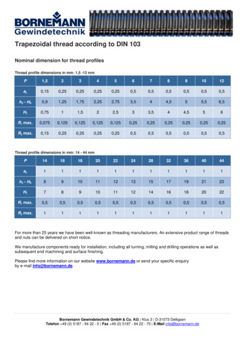
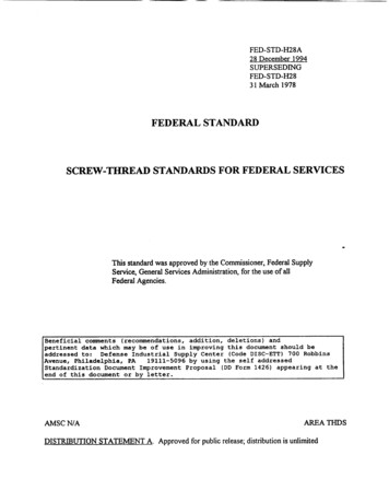
Figure 3. Acme/Stub Acme Thread Connection Length of Engagement2.1. FormulasShear Rating LOE * ShearAreaPerInch * ShearFactor * MinimumYield(lbf)SafetyFactor2.2. Intermediate Equations (Geometric Representation) 1 1 ShearAreaPerInch π * MaxMinorBoxDia * * tan(14.5 ) * MinPitchDiaPin MaxMinorBoxDia (in) 2 P 2.3. User Input Variables2.3.1.2.3.2.2.3.3.2.3.4.Length of Engagement (LOE) (in)Shear FactorMinimum Yield (psi)Factor of Safety2.4. Output Variables2.4.1.2.4.2.Shear Rating (lbf)Shear Area Per Inch (in)2.5. Reference:Machinery’s Handbook 26th Edition p.1794-17953. Acme/Stub Acme Thread Torque and Axial Load CalculationOnce thread box/pin nose has stopped moving and the box/pin makes contact at the internal or external shoulder (seeFigure 4 and 5), additional torque is translated into tension or compression causing an axial stress applied across thethread relief of the box for contact at the internal torque shoulder or across the thread relief in back of the pin for contact atthe external shoulder.Once the location of contact is known the value of the axial load can be calculated from the torque applied to the joint andvise versa. Knowing the axial load generated by an applied torque is very useful in the design of threaded connections.An important factor in the Torque/Axial Load is the coefficient of friction used in the equation. Typically values forcoefficient of friction can be found in many engineering texts. Careful selection of the appropriate coefficient of friction isnecessary to accurately determine the corresponding calculated value. Some common factors affecting coefficient offriction; temperature, surface finish (texture) of surfaces in contact, lubrication type and viscosity, coatings, materials incontact, numbers of times the joint has been assembled and disassembled.Figure 4. Acme/Stub Acme Thread connection with an internal load shoulder
Figure 5. Acme/Stub Acme Thread connection with an external load shoulder3.1. Formulas P PitchDia * µ MidPointRadius * µ AxialLoad * 2π 2 * cos φ Torque (ft-lbf)12AxialLoad Torque * 12 P PitchDia * µ 2π 2 * cos φ MidPointRadius * µ (lbf)3.1.1. External Torque ShoulderMidPointRa dius (1/4) * (MinOD BoxThreadR elief) (in)Mid-Point Radius is the assumed location of applied force3.1.2. Internal Torque ShoulderMidPointRa dius (1/4) * (MaxID PinThreadR elief) (in)Mid-Point Radius is the assumed location of applied force3.1.3. User Input nt of Friction ( )Maximum Inside Diameter (in)Minimum Outside Diameter (in)Minimum Yield (psi)3.2. ConstantsPhi ( ) 14.5 degrees3.3. Output Variables3.3.1.3.3.2.3.3.3.3.3.4.3.3.5.Torque (ft-lbf)Axial Load (lbf)Pin Tensile Rating (lbf)Box Tensile Rating (lbf)Thread Shear Rating (lbf)
3.4. ReferenceMachinery's Handbook, 26th Edition, p. 1486-14874. Acme/Stub Acme Thread Torque To Yield CalculationIf an excessive torque is used to generate an axial load, the connection could yield before the desired axial load hasbeen achieved. To determine whether the load will cause the threaded connection to yield, the minimum of the {boxtensile rating, pin tensile rating, & shear rating} is determined. Those values are used in the equation found insection 4.1 to determine the torque to yield the threaded connection. Ideally, the axial load should be less than thebox/pin tensile and shear ratings to prevent and plastic deformation to the threaded joint.4.1. Formulas P PitchDia * µ MidPointRadius * µ AxialLoad * 2π 2 * cos φ Torque (ft-lbf)124.1.1. External Torque ShoulderMidPointRa dius (1/4) * (MinOD BoxThreadR elief) (in)Axial Load Min. of {PinTensileRating, BoxTensileRating, ThreadShearRating}4.1.2. Internal Torque ShoulderMidPointRa dius (1/4) * (MaxID PinThreadR elief) (in)Axial Load Min. of {BoxTensileRating, PinTensileRating, ThreadShearRating}4.2. User Input .Coefficient of Friction ( )Maximum Inside Diameter (in.)Minimum Outside Diameter (in.)Min. Yield (psi)Factor of SafetyLength of Engagement (LOE) (in.)Shear Factor4.3. ConstantsPhi ( ) 14.5 degrees4.4. Output Variables4.4.1.4.4.2.4.4.3.4.4.4.4.4.5.Torque To Yield (ft-lbf)Axial Load To Yield (lbf)Pin Tensile Rating (lbf)Box Tensile Rating (lbf)Thread Shear Rating (lbf)4.5. ReferenceMachinery's Handbook, 26th Edition, p. 1486-14875. Thread Size Optimization (Acme/Stub Acme Threads)
The procedure outlined in Section 5.1 searches for the optimal size thread that will minimize the difference between thebox and pin tensile rating. To use the search algorithm, the user must enter the OD, ID, Pitch, and Yield Strength. Theprogram then takes over and performs the search based on the constraints input by the user. After performing thealgorithm, the program then displays the results in order of increasing maximum allowable tensile strength difference.5.1. Algorithm1.2.3.Calculate the midpoint between the Max. ID and Min. OD rounded to the closest 1/32 of an inch.Start with first thread size that is equal to or greater than the average value found in step 1.Calculate the Box Tensile Rating and the Pin Tensile Rating and the absolute difference between the Box TensileRating and the Pin Tensile Rating. Box tensile will generally be larger than Pin Tensile.4. Go to the next larger available size with an index of 1/32”5. Recalculate the Box Tensile Rating, Pin Tensile Rating and the absolute difference6. Continue until Box Tensile Rating is less than the Pin Tensile Rating (this will be thread size B)7. Recalculate the Box Tensile Rating, Pin Tensile Rating and the absolute difference for the previous and next size(A and C respectively)8. Compare the absolute difference for thread sizes A, B and C9. The thread size with the lowest absolute difference is the 1st (optimal) option10. The remaining are then listed 2, 3, 4 and 5 in order of increasing absolute difference values5.2. User Input Values5.2.1.5.2.2.5.2.3.5.2.4.5.2.5.Thread TypeMax. OD (in)Min. ID (in)PitchMin. Yield (psi)5.3. Outputs5.3.1.5.3.2.5.3.3.5.3.4.Thread Size (in)Pin Tensile Rating (lbf)Box Tensile Rating (lbf)Absolute Difference (lbf) -- Absolute Difference ABSOLUTE ([Box Tensile Rating] - [Pin Tensile Rating])
o ASME B1.5-1997 for Acme2 o ASME ANSI B1.8-1988 for Stub Acme3 o ASME B1.1 – 1989 Unified Inch Screw Threads4 Figure 1. Acme Thread . Technical Application: Positive values indicate a tensile load while negative values indicate a compressive load. The designer must identify critical compressive buckling loads at the box/pin nose. This functionality is beyond the scope of this Standard. The .