Transcription
ENGLISHBatteryProtect 48V 100A48V - 100Arev 00 08/2022
BatteryProtect 48V 100ATable of Contents1. Introduction . 12. Features . 23. Installation and wiring examples . 33.1. Precautions and installation notes . 33.2. Warning when connecting inverters and inverters/chargers . 43.3. Wiring examples . 53.3.1. BatteryProtect in a simple system . 53.3.2. BatteryProtect remote on/off switch . 63.3.3. BatteryProtect in a lithium battery system with external BMS . 63.3.4. BatteryProtect in a lithium system with external BMS and load disconnect output . 73.3.5. Two BatteryProtects for load and charger control . 83.3.6. BatteryProtect Alarm output wiring . 84. Operation and programming . 104.1. Operation modes .4.2. Programming .4.2.1. Programming via PROG pin to GND pin method .4.2.2. Programming table .4.3. Status indicator .4.4. Remote control and short circuit behavior .4.5. Error & Warning modes .101111121212125. Technical specifications . 135.1. Technical specifications . 136. Appendix . 146.1. Error and Warning codes . 14
BatteryProtect 48V 100A1. IntroductionThe BatteryProtect disconnects the battery from non-essential loads before it is completely discharged (which would damage thebattery) or before it has insufficient power left to crank the engine.It also provides an alternative to disable chargers without a remote on/off port to protect from over-voltage.Compared to the Smart BatteryProtect, the BatteryProtect must be programmed via the PROG pin to GND pin method.The BatteryProtect is a uni-directional device. It can only deal with current in one direction, so either current to a load, or currentfrom a charger, but not both currents at the same time. In addition to this, current can only flow from the IN terminal to the OUTterminal.Page 1Introduction
BatteryProtect 48V 100A2. FeaturesThe BatteryProtect offers a wide range of different features. These include: Protection of the battery against excessive discharge and can be used as a system on/off switch. A special setting for Lithium batteries. This feature allows external control from a BMS like the VE.Bus BMS or Lynx SmartBMS. If the load disconnect output of a BMS is connected to the Remote H input and the signal becomes free-floating, the loadis immediately disconnected. Ultra-low current consumption of 2mA: This is important in case of Li-ion batteries, especially after low voltage shutdown. Over voltage protection: To prevent damage to sensitive loads due to over voltage. The load is disconnected whenever the DCvoltage exceeds 64V. Ignition proof: No relays but MOSFET switches, and therefore no sparks. Delayed alarm output: The alarm output is activated if the battery voltage drops below the preset disconnect level fore morethan 12 seconds. Starting the engine will therefore not activate the alarm. Delayed load disconnect and delayed reconnect. Responding quickly within this delay, for example by reducing the load orstarting a generator or charger to charge the batteries, can prevent loads from being switched off.For a full description of all features, please see the datasheets.Page 2Features
BatteryProtect 48V 100A3. Installation and wiring examples3.1. Precautions and installation notesThere are a few basic things to keep in mind when installing a BatteryProtect:1. The BatteryProtect must be installed in a well-ventilated area and preferably close (max 50 cm) to the battery (but, due topossible corrosive gasses not above the battery!).2. Choose the correct cable size and length to match the load. Voltage drop over a long or undersized cable between thebattery plus and the BP may result in a short circuit alarm when starting-up the load, or unexpected shutdown. Youcan also find more information on selecting the right cable size and its protection in our book Wiring Unlimited.3. A properly sized fuse must be inserted according to local regulations in the cable between the battery and the BP.4. Pay attention to the correct orientation. The BP is designed to allow current to flow from IN (battery) to OUT (load) terminalsonly. Reverse currents from OUT to IN terminals are strictly forbidden and will damage the device. If you wish to use the BPas a disconnection for a charge source, you must orient the unit in the system so that the current is flowing in the intendeddirection, IN to OUT.5. The short circuit protection of the BP will be activated if you try to directly connect loads with capacitors, for example invertersor inverter/chargers, on their DC inputs. For that use case, please use the BP to control the remote on/off control on theinverter, instead of disconnecting the higher power DC line. See also the warning on the next page.6. Use a 1,5mm2 wire (included) for the GND connection, which should be connected directly to the battery negative terminal (orthe chassis of a vehicle). No other equipment should be connected to this wire.7. The pin assignment of the connectors are printed either on the front or on the side of the housing.8. The BP automatically detects the system voltage once only during initial power up. See "d" in the programming table for howto reset it when re-using the BP in a different installation.9. Do not connect the load output until the BP has been fully programmed.10. A remote on/off switch can be connected between Remote H and Remote L. Alternatively, terminal H can be switched high (tobattery positive), or terminal L can be switched low (to battery negative).11. A buzzer, LED or relay can be connected between the alarm output terminal and the battery positive. Maximum load on thealarm output: 50mA (short circuit proof).Page 3Installation and wiring examples
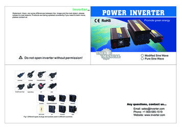
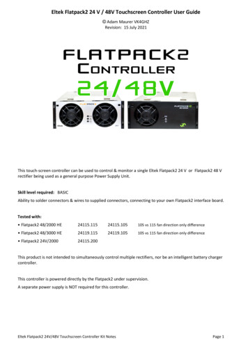
BatteryProtect 48V 100A3.2. Warning when connecting inverters and inverters/chargersUnder no circumstances is it permitted to connect inverters or inverter/chargers to a BP via their DC inputs, areverse current may flow that damages the BP. In case you want to control an inverter or inverter/charger viaa BP, you must use the BP to control the inverter or inverter/charger via its remote port. See example below.Note that the image shown below is an example for all BatteryProtect models including the smart models.DC loadsDC loadsLeft image: Inverter DC input connected via a BatteryProtect - strictly forbiddenRight image: Inverter controlled by its remote port via BatteryProtectPage 4Installation and wiring examples
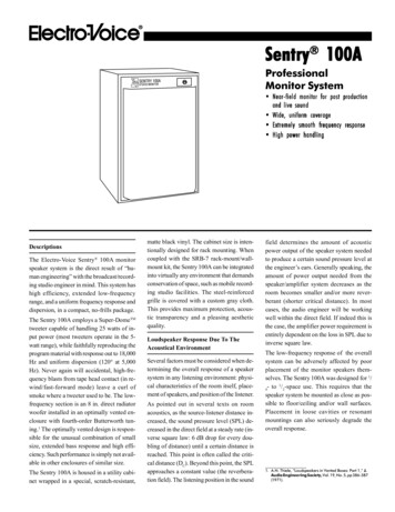
BatteryProtect 48V 100A3.3. Wiring examplesThis section contains various wiring examples to show all the possibilities of wiring.3.3.1. BatteryProtect in a simple systemThe example below shows a BatteryProtect with the wire loop (default) between L and H of the remote terminal. When the wireloop is removed, the BP disconnects the load after 90 seconds.However, if the wire loop remains plugged in and the battery voltage drops below the programmed value for under voltageshutdown (see section Programming [11]), the BP disconnects the load after 90 seconds automatically.DC loadsBatteryProtect in a simple system with wire loop between L and H input (factory default)The same example below. This time the switch is wired between battery positive and the H input of the remote terminal.When switched off, the H input becomes low. The load is disconnected after 90 seconds. When the switch is turned on again, theH input becomes high and the load is turned on with a delay of 30 seconds.This works in the same way between battery minus and the L input of the remote terminal.System on/offswitchDC loadsSwitch wired between battery positive and H input of the remote terminalPage 5Installation and wiring examples
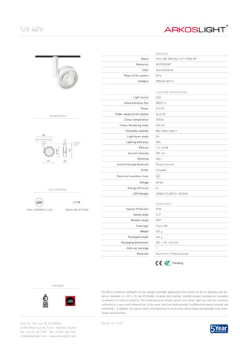
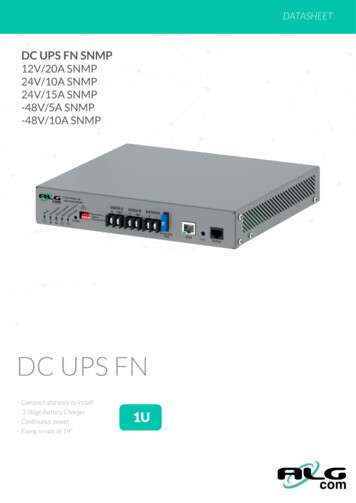
BatteryProtect 48V 100A3.3.2. BatteryProtect remote on/off switchThe below example shows a BatteryProtect in a simple system with a remote on/off switch wired to the remote terminals.This switch can be used, for example, to turn the system remotely on and off. The power consumption of the BatteryProtect isnegligible at less than 1mA when switched off (check the Specifications chapter).Systemon/offswitchDC loadsBatteryProtect with remote on/off switch3.3.3. BatteryProtect in a lithium battery system with external BMSThe image below shows a BatteryProtect in a lithium battery system with external BMS. The external BMS (Victron Lynx SmartBMS in this example) has an ATD (allowed to discharge) and ATC (allowed to charge) output. Designed as a dry contact, ATDand ATC function as a switch that directly controls the BP via its remote terminal.For this, the BatteryProtect must be programmed to Li-ion mode.The dry contact is wired between the L and H connectors of the remote terminal.If, for example, ATD opens in the event of a lithium battery cell undervoltage, the BP will immediately disconnect the load withoutdelay.The BP will remain disengaged for 30 seconds, even if ATD closes within this period. After this 30 seconds, it respondsimmediately and connects the load to the battery.Please note that the under voltage thresholds and alarm output of the BP are inactive in this mode.If you have a lithium battery with internal BMS (so-called drop-ins) that does not have an output for controllingloads or chargers, the BP must be programmed in mode A or B. Mode C is not applicable in this case.Figure 1.BP-48VLynx Smart BMSDC loadsFuseBMS cablesATD (allowed to discharge)BatteryProtect in Li-ion mode controlled by ATD from a Lynx Smart BMSPage 6Installation and wiring examples
BatteryProtect 48V 100A3.3.4. BatteryProtect in a lithium system with external BMS and load disconnect outputThis wiring example shows a BatteryProtect wired into a lithium system that is controlled by an external BMS (Victron smallBMSwith pre-alarm). This BMS has a load and a charge disconnect output that can be wired directly to the BatteryProtect H input ofthe remote terminal.As with the previous example, it is necessary to program the BP into Li-ion mode (see chapter Programming [11]).If, for example, the smallBMS triggers the pre-alarm because of an imminent low cell voltage, the load output becomes freefloating (normally high) when there is an actual low cell voltage and the BP will disconnect the load and remains off for 30seconds, even if it receives a restart signal (H becomes high again) within this period. After this 30 seconds, it respondsimmediately to a restart signal.If the system has been switched off due to low cell voltage, the BP will remain off for 30 seconds, even if itreceives a restart signal within this period (which is most likely the case if no other loads are connected to thebattery). After 3 reclosing attempts, the BP will remain off until the battery voltage has risen above 52V for atleast 30 seconds (which is an indication that the battery is being recharged).BP-48VDC loadsBatteryProtect uses the load disconnect of a smallBMSPage 7Installation and wiring examples
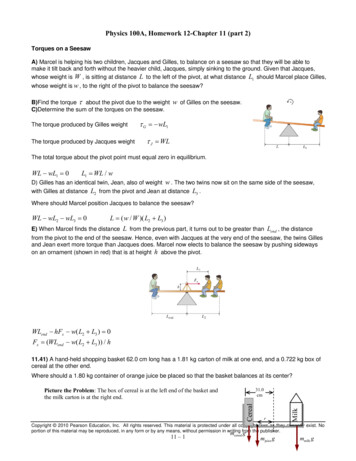
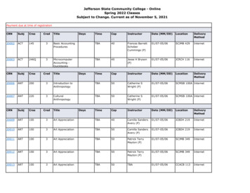
BatteryProtect 48V 100A3.3.5. Two BatteryProtects for load and charger controlIt is also possible to have several BatteryProtect in one system, for example, to control chargers and loads at the same time.If the BMS signals a cell undervoltage, the BP responsible for the load will disconnect the load from the battery to protect thebattery from further discharge.If the BMS signals a cell overvoltage or too low temperature to charge the lithium battery, the BP will disconnect the charger fromthe battery immediately.Please also note the correct connection of the BPs: always follow the current flow from IN to OUT. The positive terminal of thecharger goes to the IN input of the BP.BP-48V(charge disconnect)BP-48V(load disconnect)DC loadsTwo BatteryProtects take control of a charger and a load circuit3.3.6. BatteryProtect Alarm output wiringThe alarm output can be wired e.g. to an LED, a buzzer or a relay. For this, the BatteryProtect must be programmed in therespective mode because of slight differences in the behavior. See also the section Operation modes [10] for more details.Make sure that the LED, buzzer and relay match the system voltage.Page 8Installation and wiring examples
BatteryProtect 48V 100ALEDRelayBuzzerDC loadsWiring an LED, Buzzer or Relay to the BatteryProtect outputPage 9Installation and wiring examples
BatteryProtect 48V 100A4. Operation and programming4.1. Operation modesThe BatteryProtect has three operating modes, the appropriate mode can be selected via a programming procedure (see chapterProgramming [11] ). Mode A: Buzzer or LED mode (default). Mode B: Relay mode. Mode C: Li-ion mode.Modes A and B affect the behavior of the alarm output.Mode C, the Li-ion mode, takes into account lithium batteries that have an external BMS or a BMS with load and/or chargedisconnect.Buzzer or LED mode behaviour In case of under voltage, a continuous alarm will start after 12 seconds. The BP will disconnect the load after 90 seconds andthe alarm will stop. Reconnect delay: 30 seconds. In case of over voltage, the load will be disconnected immediately and an intermittent alarm will remain on until the overvoltageproblem has been corrected. There is no reconnect delay.Relay mode behaviour In case of under voltage, the relay will engage after 12 seconds. The BP will disconnect the load after 90 seconds and the relaywill disengage. In case of over voltage, the load will be disconnected immediately and the alarm output will remain inactive.Li-ion mode behaviourOnly select the Li-Ion mode if your BMS has a load disconnect and/or a charge disconnect output. This is usually not the casefor so-called drop-in batteries with internal BMS. For lithium batteries/BMS without load disconnect output, select mode A or Binstead.Connect the load or charge disconnect (depending on application) output of the BMS to the Remote H terminal of theBatteryProtect. The load or charger is disconnected immediately when the load or charge disconnect output of the BMS switches from ‘high’to ‘free floating’. The under voltage thresholds and alarm output of the BatteryProtect are inactive in this mode. It will remain disengaged for 30 seconds, even if it receives a re-engage signal within that time period. After 30 seconds it willrespond immediately to a re-engage signal.Page 10Operation and programming
BatteryProtect 48V 100A4.2. ProgrammingThe BatteryProtect can be programmed by connecting the PROG pin to GND pin method.4.2.1. Programming via PROG pin to GND pin methodRequirements prior to programming: The battery positive must be connected to the IN terminal. Do not connect the OUT terminal yet. The included ground wire must be connected to the battery minus and the GND terminal of the BatteryProtect 48V 100A. The wire loop in the remote on/off terminal block must be removed.Programming procedure:1. Use a wire loop or a wired switch (preferably a push button) between the PROG pin and the GND pin.2. While there is a connection between the PROG pin and the GND pin, the 7-segment display will first step through theshutdown and restart voltage combinations, as indicated by the numbers 0.9 (see the Programming table [12]).3. Remove the wire loop or release the push button when the desired voltage mode is displayed.4. The display will confirm the chosen voltage and default mode (A) twice.5. Reconnect the wire loop or press the push button again, if a different operation mode (B, C or D) is required (see theProgramming table [12]).6. Disconnect the wire loop or release the push button when the required mode is displayed.7. The display will confirm the chosen voltage and operation mode twice.Push buttonPush button wired to program the BatteryProtectPage 11Operation and programming
BatteryProtect 48V 100A4.2.2. Programming tableProgramming table for BatteryProtect 48V 100A7-segment displayUnder voltage shutdown 48V systemUnder voltage restart 48V 52.0V940.0V52.8VABuzzer or LED modebRelay modeCLithium mode4.3. Status indicatorThe decimal point of the 7-segment display is used for status indication: Illuminated: the BatteryProtect is attempting to activate the output. Flash every 5 seconds: output is active. Flash every 2 seconds whilst in Li-ion mode: output ‘connecting’. When in Li-ion mode the SBP will observe a dead period of 30seconds after the remote input of the BP has become free floating.4.4. Remote control and short circuit behaviorThis section describes the behaviour of the BatteryProtect when it is controlled via the remote on/off input and when a short circuithas been detected. The BatteryProtect will connect the load 1 second after the remote input is closed. The BatteryProtect will disconnect the load immediately when the remote input is opened. When in Li-ion mode the BP will connect the load 30 seconds after the remote input of the BP has been pulled high by theBMS. This delay increases to 3 minutes in case of frequent switching. In case of a short circuit, the BatteryProtect will attempt to connect the load every 5 seconds. After two attempts the display willshow E1 (short circuit detected).4.5. Error & Warning modesThere are 4 possible error modes, indicated by the 7-segment display: E1 Short circuit E2 Over temperature / P2 Over temperature warning E3 Under voltage / P3 Under voltage warning E4 Over voltageAfter 5 minutes the error is no longer displayed to reduce current consumption.Please refer to the appendix chapter Error and Warning codes [14] for more info on each error.Page 12Operation and programming
BatteryProtect 48V 100A5. Technical specifications5.1. Technical specificationsBatteryProtectBP 48V 100AMax. continuous load current100APeak currentOperating voltage rangeCurrent consumptionAlarm output delayMax. load on alarm output250A32 - 60 VWhen on: 2mA When off or low voltage shutdown: 1.5mA12 seconds50mA - short circuit proofLoad disconnect delay90 seconds (immidiate if triggered by a BMS)Load reconnect delay30 secondsDefault thresholdsOperating temperature rangeConnectionMounting TorqueWeightDimensions (hxwxd)Disengage: 42 V Engage: 48 VFull load: -40 C to 40 C (up to 60% of nominal load at 50 C)M89 Nm0.8 kg 1.8 lbs62 x 123 x 120 mm2.5 x 4.9 x 4.8 inchPage 13Technical specifications
BatteryProtect 48V 100A6. Appendix6.1. Error and Warning codesThis appendix gives a list of error and warning codes and possible solutions.E1: Short circuitShort circuit protection is activated in the event of a short circuit, an overload condition or excessive inrush current - such as whenattempting to directly power an inverter or inverter/charger.1. Check for a potential short circuit condition.2. Confirm that the load current draw does not exceed the BP current rating.3. Use the BP to control the remote on/off switch on loads with high inrush currents, rather than directly powering/disconnectingthe DC supply.4. Check for loose/high resistance connections and ensure that appropriate gauge wiring is used in the installation.E2: Over temperatureOver temperature protection is activated in the event of excessive internal temperature.1. Confirm that the load current draw does not exceed the BP current rating.2. Check for loose/high resistance connections and ensure that appropriate gauge wiring is used in the installation.3. Do not install the BP unit in a location exposed to high temperature or radiant heat - relocate BP to a cooler position orprovide additional active cooling.E3: Under voltageUnder voltage protection is activated in the event that the input voltage drops below the under voltage limit selected for 90seconds.1. Switch off/disconnect loads and recharge the battery.2. Check charging system and battery for proper operation.E4: Over voltageOver voltage protection is activated in the event that the input voltage exceeds 64V.1. Confirm the configuration of all charging devices in the system - particularly system voltage and charge voltage settings.2. Check charging system for proper operation.3. Confirm BP system voltage configuration is correct.Page 14Appendix
Operating temperature range Full load: -40 C to 40 C (up to 60% of nominal load at 50 C) Connection M8 Mounting Torque 9 Nm Weight 0.8 kg 1.8 lbs Dimensions (hxwxd) 62 x 123 x 120 mm 2.5 x 4.9 x 4.8 inch BatteryProtect 48V 100A Page 13 Technical specifications