Transcription
CLEAR-COM INSTRUCTION MANUALINTRODUCTION1. 1GENERALThe Clear-Com system is a closed circuit intercommunication systemdesigned for clear- two-way communication in high noise environments.Low impedance lines (200 ohms) and specially designed circuitry make thesystem virtually immune to RF and dimmer noise. The basic system consistsof a main station and from one to 40 remote stations, joined by inter connecting cable. Main stations are available in portable cases (singlechannel CS-100 and dual-channel CS-200), as well as rack-mountable enclosures(CS-100K and CS-200K). There are several interchangeable remote stations:the RS-100A "belt pack", the KB-100 liKing Biscuit" mic/speaker unit, theMR-102 wall-mount unit, the KB-lll wall mount unit with speaker, and theKB-lllP portable remote unit with speaker. The master gain control, locatedon the main station rear panel, allows the operator to set the overall gainin accordance with the number of remote stations being used.All remote stations, except the MR-102, have adjustable side tonewhich enables the user to vary the amount of his or her own voice in theheadset, handset or speaker for maximum intelligibility with minimum chanceof feedback. All remote stations have their own volume control for ad justing the level in the earpiece (s), call switches and call lights forsignaling from other stations.Clear-Com is a distributed amplifier system, with each remote stationhousing its own mic preamplifier and headset power amplifier ( 20dBm maxoutput). The main station supplies 28V dc necessary for operating allcircuits, and power is carried to remote stations via the same interconnectingcable which carries the audio signals. The main stations also have anauxiliary, line-level input with its own volume control which allows mixingof an external program with the intercom line. This is useful for programmonitoring.A power-supply only main station is available, the model PS-3000.Standard microphone cables (XLR-3 type connectors) are used for inter connection in most cases; the WP-l and WP-2 wall-mount connector platesmay be used in some permanent installations. Interconnect cables, and a4-way splitter (the Quadropuss) are available from Clear-Com.78- 1
SECTION IIINSTALLATI ON2.12.1.1EQUIPMENT SELECTIONFIXED SYSTEM MAIN STATIONSFor permanent intercom systems, main station equipment is usuallymounted in a standard 19" rack fo ,r security and convenience. For thisreason, we recommend either the CS-100K single-channel main station orthe CS-200K dual-channel main station. However, if an intercom stationis not needed at the area where the equipment rack is located, then thePS-3000 power supply (without intercom station) should be s bstituted.2.1.2FIXED SYSTEM REMOTE STATIONSIn permanent installations, it is usually desireable to run inter connecting cables through conduits, and to bring them to wall-mountedremote stations, or to wall plates for connection to portable remotestations. We recommend the MR-102 wall-mount remote station, or theKB-lll wal l mount remote station with paging speaker. If you don'twish to have the remote station built into the wall, then use ourWP-l or WP-2 wall plates with any of our portable remote stations;the RS-100A IIbelt pack", the KB-100 liKing Biscuit mic/speaker station,or the KB-lllP headset/handset station with paging speaker.ll2. 1 .3PORTABLE SYSTEM MAIN STATIONSFor portable intercom systems, main station equipment must becompact, lightweight, and easily moved for storage. The CS-100 single channel main station and CS-200 dual-channel main station fulfill theserequirements.2. 1.4PORTABLE SYSTEM REMOTE STATIONSThe RS-100A "belt pack" is the key to our truly flexible portableintercom system. Because each RS-100A has a pair of input and extensionconnectors, many stations may be "daisy chained" together along oneinterconnect path. This saves cable and simplifies installation andbreak down.The KB-'lOO liKing Biscuit mic/speaker remote station is ideal foruse in remote trucks and in studio control rooms, as well as on stageduring setup of live shows. It can be used either in push-to-talk mode,or in an optional IIhands-free mode where the speaker and microphone bothfunction simu H aneousl'y. In the latter mode, 2-way cOrrTTlunication is possibleat distances up to three or four feet, depending on ambient noise levels.llll1/78- 2
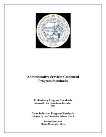
2.1.5. CLEAR-COM HEADSETS AND HANDSETSClear-Com has three standard headsets available, all with boom mounted, noise-cancelling microphones. The CC-240 is a double-muffheadset, ,and the CC-75 is a single-muff headset, both with boom-activatedmics. The PH-7 is a double muff headset which has wider frequency response,greater isolation from ambient noise, and sturdier physical constructionthan the CC-240, and no mic switch in the boom. All units have fie1d replaceable cords. The HS-6 telephone-style handset is interchangeablewith the above headsets.All remote stations can drive 2 headsets with only a slight reductionin level. A V-cord can be made up using the diagram below and the specifiedwire. Extension cords for the headset can also be made out of this same cableor other separately shielded cable such as Belden 8734, 8416 or 9454.Extensions should be limited to approximately 15' due to the possibility ofcapacity coupling between the microphone signal and the headset signal whichwould cause a loss of high frequency response or oscillation.CAUTION:DO NOT connect microphone ground and earphone ground togetherat any poi nt.Cdble:A/.{FBe{ c{ en - g 7 31.(. -I- -- - - ---- ---- -- - - --- ---8Jflb-9 S1Y-Cord2.1.6 .OTHER HEADSETSNon-C1ear-Com headsets are available from Clear-Com or local dealers.These are recommended for special applications:, '78Beyer DT-108Single-muff, high-fidelity earpiece with boom mic;may be used for monitoring and intercom.Shure SM-12Miniature, lightweight type with boom mic andhearing-aid type earpiece.- 3
2.1.6INTERFACE TO OTHER COMMUNICATION SYSTEMSThe AC-10 Adapt-a-Com is a universal adapter which enables Clear-Comto be interfaced with any other intercom or communications link. Whenexisting non-Clear-Com installations are being upgraded to Clear-Comequipment, portions of the older system can be retained. Since Adapt-a-Comworks in 2-, 3- and 4-wire systems, it virtually guarantees compatibilitywith any house intercom equipment.Because it will simulate a carbon mic, Adapt-a-Com can be pluggedinto the headset jack on a TV camera, control unit, or other 2-wire systems.Adapt-a-Com operates with telephone company and competitive model 3-wireintercoms, facilitates on-line intercom via standard telephone systems, andaids in direct communication between the studio and remote locations via2 or 4 wire dedicated TEL.CO. pairs.2.1.7AUDIO ISOLATION OF PARTS OF THE INTERCOM SYSTEMIn certain applications, it may be desireable to isolate conversationsin one section of the system. In these instances, the BA-l in-line isolatormay be used to block audio while allowing power to flow to the isolated legof the system. This inexpensive, passive device creates a quasi-dual channelsystem from a single channel, except that the main station cannot contact orbe called by the isolated leg of the system. The BA-l enables you to haveprivate local conversations along a common interconnect cable without needfor multiple cabling or several main stations. Any number of BA-lls may beused, so long as the power capacity of the main station is not exceeded.2.2 MAXIMUM NUMBER OF STATIONS AND CABLE CONSIDERATIONS2.2.1MAIN STATION CURRENT AND IMPEDANCE LIMITSAll Clear-Com main stations, induding the PS-3000 power supply, havethe same maximum output current capacity, 2 amps. For dual channel mainstations, the total current draw on both channels cannot exceed 2 amps.Due to impedance considerations, regardless of the cable lengths or mixof remote stations, 40 stations are the maximum that can be driven from onemain station. (In certain circumstances, it may be possible to use more than40 stations; contact the factory for details.)2.2.2CALCULATING THE MAXIMUM NUMBER OF REMOTE STATIONSIn installations with less than 500 feet total interconnecting cable,only the remote station current requirements need be considered. One mainstation will support up to 40 RS-100A or MR-102 remote stations, or up to15 KB-100 or KB-lll remote stations.1/78- 4
When calculating the maximum current drain, only two figures needbe considered; a maximum current drain of 40 ma in the RS-100A or MR-102,and an average current drain of 130ma in the KB-100 or KB-lll. Thus, anequation for maximum stations would be as follows:x Number Of RS-100A's MR-102 1 sY Number of KB-l 00 I s KB- 111IS 40. 15.Therefore,0.04X 0.13Y 2.02.2.3CABLESWhere cable lengths greater than 500 feet are involved, the maximumnumber of remote stations, depends on four factors; the current requirementsof each remote station, the length of the wire, the wire gauge, and the cablecapacitance. In all instances, 2-conductor, shielded interconnecting cableshould be used.A.PORTABLE INSTALLATIONS: rubber-insulated and jacketed cable shouldbe used due to its superior strength and durability. Belden 8413 mini ature cable (24 gao stranded conductors) is usable up to 500 feet.Belden 8412 (20 gao stranded conductors) is usable up to 5,000 feet.B.PERMANENT INSTALLATIONS: Vinyl-insulated and jacketed cable maybe used; it costs less and is easier to pull through conduit thanrubber insulated types. However, low capacitance cable must be used.Belden 8762 (20 gao stranded conductors) is usable up to 500 feet.Belden S'1rA (18 gao stranded conductors) is usable up to 5,000 feet.NOTE: In systems where conduit is not used, and where equipment maynot -share a common ground, it may be necessary to run an additionalground wire to tie chassis together. This may be accomplished withBelden 8770 3-conductor shielded cable.C.2-CHANNEL PERMANENT INSTALLATIONS: Permanent systems can bewired in one of two ways. First, Channel A and Channel B may berouted to two distinct areas, for use by different people. Second,both channels may be routed together and brought to WP-2 wall platesso the user can select either channel A or B. The second method canbe wired with two 2-conductor shielded cables or one multi-pair shieldedcable.Cables equivalent to the Belden types may be used, so long as theircapacitance and wire gauge are comparable. Particularly in longer runs, itis desirable to use cable which has low resistance (large diameter conductors)and low inter-conductor capacitance.- 5 1/78
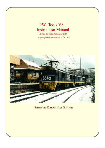
2.32.3.1LAYING OUT THE SYSTEMPORTABLE INSTALLATIONSHaving determined the number and type of remote stations you wishto use, decide on a location for the main station. It should be near asource of 115V AC (power consumption is approximately 80 watts.) Thereare six parallel outputs available on the rear panel of the CS-100, andtwo sets of 3 parallel outputs on the CS-200. Any remote sta t ions can beconnected directly to the 6 outputs. Additionally, remote stat ions can beadded by "daisy chaining" them to one another and/or by using the QP-100Quadrapuss splitter. Cables should be routed away from heavy AC powersources, such as lighting panels, electric motors, etc.2.3.2PERM'ANENT INSTALLATIONSThe same general considerations apply here as for portable systems,as described in the preceding paragraph. Additionally, cables should beinstalled in accordance with approved local building codes. Class IIwiring may be used. Connections to wall-plates or wall-mount remotestations are shown in the di agrams.2.3.3ISOLATED CHANNELSThe BA-l In-Line Isolator can be installed anywhere in the system.For example, plug it into one output connector on the rear panel of themain station to create an entire isolated channel. Alternately, plug itinto a remote station at the end of a cable run to isolate further remotestations while using a minimum of additional interconnect cable.Typical Coliseum Intercom System1/78- 6
OPERATION OF THE SYSTEMOPERATION OF THE CLEAR-COM SYSTEM IS QUITE SIMPLE, AS FOLLOWS:1. CONNECT MAIN STATION to all remote stations with interconnecting cable.NOTE: Before connecting rear panel interconnecting cables, shut poweroff and hold call button depressed until call light(s} go out.2. PLUG IN HEADPHONES at main station and remote stations into HEADSET CONNECTORSat front panel. (To locate connectors and controls, see Figure l.)Headset connectors in main station are wired in parrallel. Use one or both.3. SE T I ASTER GAIN SET at rear panel of main station for overall system level tocompensate for number of remote stations in system. (CS-200 has one gain controlfor each channel.) Under high noise conditions, turn master gain DOWN and speakwith microphone very close to the mouth.4. SET HEADSET VOLUME CONTROLS at main station and remote stations for individualvolume level. Volume controls are located on front panel.5. TO SIGNAL stations where headphones may have been removed, press CALL BUTTONon front panel and CALL LIGHT will go on. Call lights light up at all stationssimultaneously.6. THE AUXILIARY INPUT CONNECTOR on front panel of the main station provides forexternal program feeding into the entire system. (See schematics for connectingdetails). The AUXILIARY VOLUME CONTROL is located directly on top of theauxiliary input connector and controls the auxiliary input volume to the system.7. THE CS-200 MAIN STATION can communicate with two separate channels, A and B.THE CHANNEL SELECT SWITCH which is located on the front panel of the mainstation, can be switched to positions A, B or A B. The A or B positionenables the main station to communicate with either channel A or B, respectively,while the A B position enables the main station to communicate with bothsimultaneously. Regardless of the position of the switch, remote stations onchannel A can always talk to other remote stations on A, but A cannot communicatewith remote stations on channel B, and vice-versa. Also, note that the calllights are always operative from main station to both channels A and B, regardlessof the switch position.8. CAUTION:A}DO NOT allow belt packs to come into contact with other piecesof electrical equipment. An improper ground or short in a pieceof electrical equipment touching a Clear-Com remote station cancause a hum or a buzz in the system. When connecting remotestations to electrical equipment, make sure the equipment isproperly grounded.B}DO NOT wear the remote stations in wet weather without ensuringthat the station is properly grounded.- 7 1/78
OPERATION OF SYSTEMPS-3000 INTERCOM POWER SUPPLYDESCRIPTIONThe PS-3000 is a regulated intercom power unit designed to power all Clear-Comremote stations. Typically, it can be installed in areas not requiring a headsetfunction, i.e., isolated rack bays.The PS-3000 su-plies 30v at 2 amps and is capable of supporting a minimum of40 Clear-Com remote stations. It is protected against shorts in the cable bycurrent foldback in the regulator circuit and provides visual indication of suchconditions on the front panel system. The unit has provisions for an auxillaryprogram input to the intercom system with the level adjustable from the frontpanel.INSTALLATION' AND OPERATIONThe PS-3000 can be mounted in a standard 19" rack. Because the PS-3000 candissipate a considerable amount of heat, it is ,r ecommended that at least aninch of space be allowed above the unit to facilitate ventilation.All interconnections to the unit are made from the rear panel. Four parallelD3M connectors are provided for system output. As in any Clear-Com system,the lines to the remote stations may be "home-runs" or t he stations may be"daisy chained." Once the system has been set up, the overall level may beadjusted with system level control.If, at any time, short circuit conditions are encountered, the problem canusually be isollated by removing the interconnect cables from the unit, oneat a time, until the short circuit indicator goes out. It may be necessaryto shut the unit off for a few seconds to reset the short circuit indicator.An internal 1-1/2 amp slow-blow fuse protects the PS-3000 in case of internalpower supply failure. If the fuse repeatedly blows, it means the power transistoror a component on the p.c. board has failed. The cover is held on by "snap on"fasteners. To remove - pull cover up hard.- 8 1/78
TROUBLE SHOOTINGSYMPTOMCAUSEREMEDY1)System is totally dead, power switchlight doesn't come on.Circuit breaker open.A.C. power failure.Reset circuit breaker.line.2)Circuit breaker trips repeatedly orshort circuit LED remains lit (PS-3000 only)Shorted or mis-wired inter connect cable. Defectiveremote unit.Remove cables from main station oneat a time until faulty line is isolated.Check for shorts between pins 1 and 2.3)OscillationFeedback caused by unusedheadset left with mic onand volume turned up.Turn off mics on all unused headsets.4)Call light doesn't work.Bulb burned out.Unscrew lens from lamp holder.lamp with GE 327.5)Individual Remote Station malfunction.Faulty remote station,headset or cable.Replace suspect unit with known goodunit. Defective remote stations orheadsets should be returned to factoryfor service. There are no userservicable parts in these units.6)Hum or Buzz in system.Inductive pickup caused byclose proximity of main orremote station to power linesor transformers.Relocate offending unit.Ground loop caused byimproper grounding of system(See installation instructions)Reverse power cord.10-ohm chassis ground resistor(Rl CS-200) in main station open.(Note: This is caused by thesystem ground coming in contactwith something that is "hot"with respect to main stationearth ground. Should this occur,a careful check of the systemground and A.C. distribution inyour location is recommended.)Open main station by removing 2 screwsin handle and unscrewing 4 feet. Slideoff cover and check 10 ohm resistor onthe bridge rectifier terminal strip.If open, replace1/78- 9 Check A.C. powerReplaceLift ground.
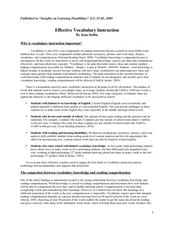
SYSTEMINTERCONNECTIONDIAGRAMCS-100CS-200., . /PS-3cxx) D3F(UQ caMD3MD3MD3MD3M(UOOGJOQ \.U0., "PIN CONNECTIONSFOR CABLEINTERCONNECTBElLEN 8413TO OTHE STATIONS- 10 CABLEPIN 1 SH IELDPIN 2 - 28VWSPIN 3 - AUDIO
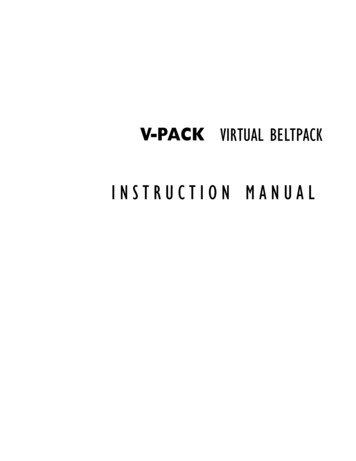
CS-100/CS-100K MAIN STATION (FRONT PANEL)FIGURE 3POWERSWITCHCALL umeVolumeHEADSET JACKSAUXILIARYINPUTCONNECTOR@ColiCALLBUTTON* * * * * * * * * * * * * * * * * * * * * * * * * * * * * * * * * * * * * * *CS-100/CS-100Kr AINSTATION (BACK PANEL)INTERCONNECTCABLEOUTPUTSCIRCUITBREAKER 0 PUSh OresetMASTER GAIN SETCORDFIGURE 41/78- 11
CS-200/CS-200K MAIN STATION (FRONT PANEL)FIGURE 1POWERSWITCHCALL LIGHTCHANNEL A0 :10@Callc" nel' eledl"l""Volume\/olU!TI&- OL HEADSET JACKSCALL LIGHTCHANNEL BCHANNEL A-B SELECT SWITCHAUXILIARYINPUTCONNECTOR* * * * * * * * * * * * * * * * * * * * * * * * * * * * * * * * * * * * * *CS-200/CS-200K MAIN STATION (BACK PANEL)INTERCONNECTOUTPUTSCHANNEL AMASTER GAIN SETCHANNEL ACIRCUITBREAKER@Pusl,.tOre etOUTPUTSCHANNEL BMASTER GAIN SETCHANNEL BFIGURE 21/78- 12 POWER- CORD
, 'J REVISIONS)"1O(SCRIPTIONLT"1f 1 :) "'TEDrp-t:· · -·M·::" r. S.o'PPRO'lED1'-"" 1Nlc.""\t.1.'-1·I iqPl.V OLU . E.IfI--r ,,'B I -I"C'"I f1 )\C w:l l- - - - -1-1NP): PO 11101.JhI"'"AIIIcp ,\Y'--- -- . 1'''''''I111-4146 I - --BIIIIS," 1 c.s1(0)l'I "Mfa3 .,ut' . 0".1:' 5.tf1it:Z.'3""1L-atO3.,1(")1CALLl1SWITC.H4 -.J. 2.Rli15K - .1 ,LCALLLAMPCALL!"AoIliP.r:: CI'-i- - - -BI1 I.::.!.!.wi C2.- p.c. S . -.J A 1ll1I1I I-- -- r 'rp lHAI. . A CI CONN t. ORSJ4IJ6 p --- -- ---IKr - - -.,1"' S2., I'O'oIlR 1J?1'7103-O " - .! .!}' "'-6 .§!.OZ.815 1A11101 ,'I. IIH1L6l O CLT1API.J"r.8Asa3A& -. FA; ! I\ 'YiO :.OAJI-E (lear( CIn.-.rcan .,.,.0"'.'"0'"''OT"[ I SP cm(DrR4CTtON 0ace0. PPROVAl IMRi\l;.CH C" [' :I ."GUS C 5 - 2.00 SC.HE.MATIC.(FULL 5"5TEN\'"mJ1,1-11-111111 1,-7' AI"SI7rnAAWING NO
J l DK13 I HVISfDc 1P\NR , SUPPLY \lUV1".-.0O(SCRIPTIONLT" PI, !.1'1·',.71 I 1(1(,.M005::r B-'-,IIIIrI'f rIII1 v.CoI IL .2. O I IIIII3,, 1(o .n.I-J SWIlOI!- -- O ""-I---- ----'':1 5R2.I .C.I I(!ILLL.AlAPIt::i f 51["'LL. , I . I . fL!l.3AtJ.i71 02. C · O p S'i5 . .J.Il!.O.r(I P3JYLI\ S HCBljV-;YY''-----1 -----,.J7 !t\" .--- r' ' 3 CLTTAPl,O-- - --() "o "'ll(,. .II·.J ""\'C .JJAI'O".'":IF\560( (."GUSIE Ca--. C -()fTt. .C S - IOO SO-\c.N\I\'-\C,( \ \JLL SYSTEM)C;:.J -.j'I",,"uOh'( IS( '''1:Cl Ji[ O3A 7 r,. . . flO . SSCA.l [ SIZE "MMC NO
CS-I00/CS-200 PARTS LISTITEMPART #DESCRIPTIONREF. DES.CS-I00\1fY.CS-200QTY.11800Choke, Fi 1 terLl1124805Diode, 3A IN540107,8,9,1044315232000 mfd 35VCl,2241529.01 mf/l.4kV Capaci torC33355202.5 Amp Circuit BreakerCBl1163900Call Light AssemblyII,1273901#327 Lamp,128211304M ConnectorsJ 1, J2229210203F ConnectorJ311102103D3r1 ConnectorsJ4 - J966114701250K Pot 3/8 " BushingPI,P222124702lK Pot 1/4" BushingP3,P412137103Amplifier Modul ePCl011471 02Amplifier Modul ePCl1015410210 ohm 1/4w Re si storRl11165100Push ButtonSl11175102Power Swi tchS211185602Power TransformerTl11196000Power Cord112071203 Position Lever Swi tch/Plug Assembly01212401Knob11222402Feet44C2I1228V.S3
SPECIFICATIONSCS-100/CS-200 MAIN STATIONAMPLIFIER:Solid State IC plug in printed circuit amplifiermodule including signalling circuit. Currentlimited and short circuit protected.FREQUENCY RESPONSE:250 Hz - 10 KHz (-3 dB ref. to 1 KHz) with a risingresponse to enhance voice intelligibility.HEADSET MICROPHONE INPUT LEVEL:-55 dBm.HEADPHONE OUTPUT LEVEL:9 volts rms into 600 Jl.maximum. (-20dBm)DISTORTION:Less than 0.5%.SYSTEM IMPEDANCE AND LEVEL:Approximately -25 dBm into 200master gain control settings)AUXILIARY INPUT AUDIO LEVEL:100 mv into 600 Jl. mi nimum.CHANNEL SEPARATION (CS-200):" 45 dB.HEADSET INPUT CONNECTOR:2 - 4 pin connectors (D4M)(Level dependent onINTERCONNECT OUTPUT CONNECTORS:CS-100:CS-200:Channel A:Channel B:6 each in parallel, Switchcraft D3M.3 each in parallel, Switchcraft D3M.3 each in parallel, Switchcraft D3M.AUXILIARY INPUT CONNECTOR:Switchcraft D3M.POWER SUPPLY:28 volts circuit breaker protected.CAPACITY:Will support up to 40 RS-100A or MR-102 remotestations or 15 KB-100 or KB-lll remote stations.POWER REQUIREMENTS:115/230 volts 50-60 Hz.DIMENSIONS:CS-100/CS-200:CS-100K/CS-200K:9.5"L X 4"H X 8.5"D.19"L X 3.5"H X 9.125"D.WEIGHT:CS-100/CS-200:CS-100K/CS-200K:6 1bs. 14 oz.6 1bs. 15 oz.80 watts maximum.
PORTABLE SYSTEM REMOTE STATIONS The RS-100A "belt pack" is the key to our truly flexible portable intercom system. Because each RS-100A has a pair of input and extension connectors, many stations may be "daisy chained" together along one interconnect path. Thi