Transcription
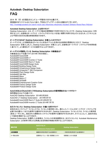
BIM for Construction IndustryWorkflowThis self-guided tutorial will cover recommendedpractices for using BIM in Construction and itsassociated workflows. Several workflows will behighlighted, including Constructability Modeling,Multidiscipline Coordination, Quantification andField Layout. These workflows will highlight thecapabilities of the Autodesk BIM Solutions forConstruction, as well as Autodesk BIM360 cloudbased offerings and how they benefit a wide rangeof professionals in the Construction industry.Lesson 1:Constructability ModelingClick here to download the Lesson 1 Sample DatasetIn this lesson, we will explore the tools andcapabilities you can use to add the constructiondetail to your design intent models. We will focuson how to consume 2D information, use it to buildour 3D models, and then how to add or configure amodel for construction detail.In the following exercises, you will: Convert 2D information into a 3D model Add construction information to the model Configure the model for preconstructionactivities Create and manage assemblies Create detailed exploded viewsExercise 1 – Convert 2D Information into a 3DModelA typical deliverable from our design teams todayis 2D paper or digital construction documents. Itcan be a challenge to use this 2D information tobuild the models needed to gain the maximumvalue from BIM in our preconstruction processes.Here we will look at specific tools in AutodeskRevit for consuming this information easily andaccurately.Click here to start video1. In Revit, open New Project.rvt.2. In the Project Browser, verify the GroundFloor view is the active view. The current viewPage 1
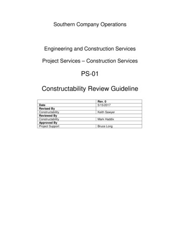
will be Bold. Double-click the view to make itcurrent.3. To link a CAD file of the Ground Floor plan, onthe Insert tab, Link panel, click Link CAD.4. In the Link CAD Formats dialog box: Navigate to the folder where the datasetsfor this exercise are saved. Select Medical Office – GroundFloor.dwg. From the Positioning list, select Auto –Origin to Origin. Click Open.The CAD file is linked into the project.5. On the Architecture tab, Datum panel, clickGrid.6. On the Modify Place Grid tab, Draw panel,select Pick Line.This allows you to pick lines from the linkedCAD file.Page 2
7. To specify the line to convert to a grid line, selectthe line as shown.A Revit gridline with tag is created from theCAD line.8. Select the tag to rename it.9. For the new name, enter A.10. Repeat the steps to create grid lines using theCAD lines B and C.The grid bubbles are placed on the right sideof the grid lines and they are automaticallynumber correctly.Page 3
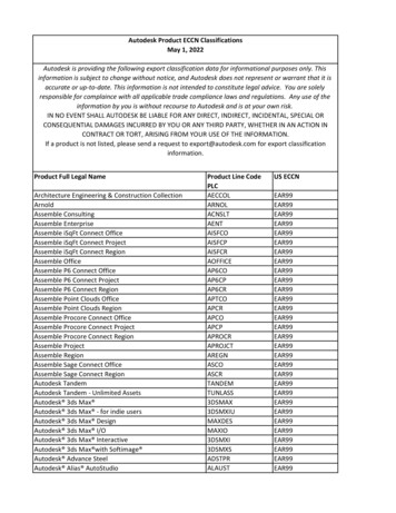
11. Repeat the steps to create grid lines using theCAD lines 1-6.12. On the Architecture tab, Build panel, clickWall.13. In the Properties palette, from the TypeSelector, select Exterior 16”.14. On the Options bar, from the Location Linelist, select Finish Face Exterior.15. To specify the start point of the wall, select apoint near grid line 12 as shown.Page 4
16. Press SPACEBAR to flip the orientation of thewall.17. To specify the end point of the wall, select apoint as shown.18. Continue to trace several of the exterior wallsfrom the CAD file.Notice that only the outside edges of the wallsare displayed in the view.19. On the View Control bar, click Visual Style Wireframe.This will allow you to see through the walls tothe linework of the cad file.Page 5
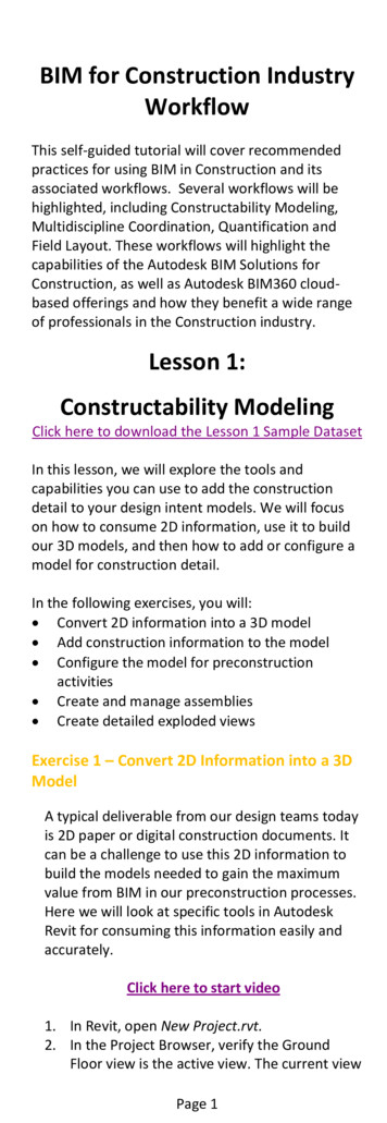
20. In the Properties palette, from the TypeSelector, select Interior – 4 7/8”.21. On the Options bar, from the Location Linelist, select Finish Face Exterior.Page 6
22. To specify the start point of the wall, selectthe end point of the CAD wall near the gridintersection E6 as shown.23. Press SPACEBAR to flip the orientation of thewall.24. To specify the end point of the wall, select apoint as shown.25. To specify the end point of the next wall,select a point as shown.26. Press ENTER to end the wall segment.27. Add another interior wall as shown.Page 7
28. On the Architecture tab, Build panel, clickDoor.29. Place the two doors as shown.30. Close the file. Do not save changes.Page 8
Exercise 2 – Add Construction InformationIn this section we will explore the capabilities ofRevit to add additional detail to the constructionmodel we have created. We will add parametersand properties to our models to ensure that wehave the correct information needed whenconsuming our models in downstream activitieslike quantification, planning and coordination.Click here to start video1. In Revit, open Medical Office – Architectural –Exercise 2.rvt.2. In the Project Browser, under Floor Plans,double-click Ground Floor to activate theview.3. In canvas, zoom in to the red clouded area asshown.4. On the Architecture tab, Room & Area panel,click Room.5. On the Tag panel, verify Tag on Placement isselected.Page 9
6. Click within the area as shown to add a room.7. Add another room to the area as shown.8. Press ESC to end the command.9. To select the room, hover over it until it ishighlighted. Then click.Page 10
10. On the Properties palette: Under Identity Data, for Number, enter1303. For Name, enter EXAM 3-3. For Base Finish, enter VB. For Ceiling Finish, enter ACT. From the Wall Finish list, select PNT-1. From the Floor Finish list, select VCT-1.11. Repeat the steps to change the properties ofthe other room as shown.12. Notice that the tags reflect the info entered inthe Properties palette.Page 11
13. In the Project Browser, underSchedules/Quantities, double-click RoomSchedule to open it.14. Verify EXAM 3-3 and EXAM 3-4 are listed inthe schedule.15. Close the Schedule.16. Verify the Ground Floor view is the activeview.17. On the Annotate tab, Tag panel, click Tag byCategory.18. On the Options bar, clear Leader.19. In canvas, select the two untagged doors inthe clouded area to add the tags.Notice that the tags do not have values inthem.20. Press ESC to end the command.21. Select the door on the right.22. On the Properties palette, under IdentityData, for Mark, enter 1303.The door tag updates to display the doornumber.Page 12
23. Repeat the steps to enter the door numberfor the door in room 1304.24. In canvas, select the wall as shown.25. On the Properties palette, click Edit Type.26. In the Type Properties dialog box, underIdentity Data, for Type Mark, enter I1. ClickOK.27. On the Annotate tab, Tag panel, click Tag byCategory.28. On the Options bar: Select Leader For Length, enter ¼”.29. Select a few walls outside the exam rooms toplace wall tags.Notice that all walls of the same type willdisplay the Type Mark value in their tags.30. Close the file. Do not save changes.Page 13
Exercise 3 – Configure the Model forPreconstruction ActivitiesWe further enhance our BIM for constructionprocesses by configuring the building componentsto better suit the construction intent for ourproject. We start by dividing larger buildingcomponents into the pieces or sections needed tosuit construction practices. This is importantbecause most design intent models do not takeconstruction practices into account when they arecreated. With these division tools, we can take aconcrete wall, divide it into the sections neededto represent individual pours, and add criticaldetail to the sections like connection details orconduit chases.Click here to start video1. In Revit, open Medical Office – Architectural –Exercise 3.rvt.2. Verify that the 3D View - Roof Constructionview is the current view.3. In canvas, select the large exterior wall withthe two ribbon windows.4. On the View Control bar, click TemporaryHide/Isolate Hide Element.Page 14
5. In canvas, select the large flat roof.6. On the Modify Roofs contextual tab, Createpanel, click Parts.7. On the Properties palette, under IdentityData, select Show Shape Handles. Click Apply.8. Use the shape handles to stretch each layer ofthe roof independently.9. Press ESC to clear the selection.Page 15
10. On the Properties palette, from the PartsVisibility list, select Show Original. Click Apply.The original roof is displayed.11. Close the file. Do not save changes.Exercise 4 – Create and Manage AssembliesOnce all of our building components are divided andthe construction detail needed is added, we can useassemblies to pull components together asnecessary to best represent our constructionpractices again. Here we will take several buildingcomponents that have been modeled separatelyand combine them into an assembly. The assemblyallows us to document, add even more detail, andmanage these components easily.Click here to start video1. In Revit, open Medical Office – Structural –Exercise 4.rvt.2. Verify the 3D – Exercise 4 view is the currentview.In canvas, select the 16 elements that makeup the entrance canopy. The back threecolumns are intentionally left out.Use CTRL select to add items to a selectionset, SHIFT select to remove items.3. On the Create panel, click Assembly.Page 16
4. In the New Assembly dialog box: From the Naming Category list, selectStructural Framing. For Type Name, enter Canopy. Click OK.5. Press ESC to end the command.6. In canvas, select the assembly.If you select any part of the assembly, theentire assembly is selected.7. On the Assembly panel, click Edit Assembly.8. On the Edit Assembly panel, click Add.9. Select the three columns that were left out ofthe assembly previously.10. On the Edit Assembly panel, click Finish.11. On the Assembly panel, click Create Views.12. In the Create Assembly Views dialog box: For Scale, select ¼” 1’-0”. Under Views to Create, select the viewsas shown.Page 17
Verify Sheet is selected.From the Sheet list, select E1 30 x 42Horizontal. Click OK.13. In the Project Browser, expand Assemblies Canopy. Double-click Detail View: DetailSection B to open the detail view.14. On the View Control bar, click Detail Level Fine.The materials are displayed with more detailin the view.15. On the Annotate tab, Dimension panel, clickAligned.16. To specify the first reference, select the lineas shown.Page 18
17. To specify the second reference, select theline as shown.18. To specify the third reference, select the lineas shown.19. To specify the dimension location, select a pointto place it as shown.20. Repeat the steps to place another set ofdimensions on the opposite elements.Page 19
21. Press ESC to end the command.22. On the Annotate tab, Text panel, click Text.23. On the Modify Place Text tab, Format panel,click24. To specify the leader start point, select apoint as shown.25. Specify a leader second point as shown.Page 20
26. Specify the leader third point as shown.27. For the text value, enter ADD NOTES.28. Click in a blank area of the canvas to specifyyou are done entering text.29. Press ESC to end the command.30. On the Project Browser, under Assemblies Canopy. Double-click Sheet: A101 – Sheet toactivate the sheet.31. Drag the 3D View: 3D Ortho view from theProject Browser onto the sheet.32. Drag the Detail View: Plan Detail view fromthe Project Browser onto the sheet.33. Drag the Detail View: Detail Section B viewfrom the Project Browser onto the sheet.Page 21
34. Close the file. Do not save changes.Exercise 5 – Create Exploded ViewsThe last type of construction detail we can add toour BIM is to take specific building components orcritical elements, and create exploded views of theobjects to create enhanced documentation andbetter communicate intent for our projectstakeholders. Here we have a wall connection detailthat represents a critical component for theconstruction process that we need to ensure isaccurately communicated to the installers on site.Using straight forward navigation and easy to useselection tools, we simply grab the components weneed, and move them graphically to gain thedesired look and view of the details. This view issaved with our model, and can be added to anydocument or sheet, and annotated to furtherenhance the communication needed to ensure clearunderstanding.Click here to start video1. In Revit, open Medical Office – Structural –Exercise 5.rvt.2. Verify the 3D – Exercise 5 view is the currentview.3. In canvas, select the 9 elements that make upthe sloped roof framing at the West (left) sideof the building.Page 22
4. On the View panel, click Displace Elements.The selected objects become a displacementset.5. Use the blue control gizmo to move thedisplacement set in the Z direction.6. On the Properties palette, for Z Displacement,enter 50’.7. On the Displacement Set panel, click Edit.8. On the Edit Displacement Set panel, click Add.9. In canvas, select the two columns as shown.Page 23
As you select them, they are added to thedisplacement set.10. Select the additional elements as shown.They are added to the displacement set.11. On the Edit Displacement Set panel, click Finish.12. In canvas, select the 5 elements as shown.Page 24
13. On the View panel, click Displace Elements.14. Use the red control gizmo to move thedisplacement set in the X direction.15. In canvas, select the first set of displacementelements that make up the sloped roof framing.16. On the Displacement Set panel, click Edit.Page 25
17. On the Edit Displacement Set panel, click Add.In canvas, select the column as shown.18.19.20.21.On the Edit Displacement Set panel, click Finish.In canvas, select the floor as shown.On the View panel, click Displace Elements.Use the blue control gizmo to move thedisplacement set in the Z direction.22. Press ESC to clear the selection.23. Use the ViewCube to rotate the view as shown.24. In canvas, select the displacement set as shown.Page 26
25. On the Displacement Set panel, click Path.26. Click on some of the corners of displacementsets to add path lines to the exploded view.Page 27
27. Close all files. Do not save changes.Lesson 2:Multidiscipline CoordinationClick here to download the Lesson 2 Sample DatasetThe next preconstruction process we will exploreusing our BIM for is multidiscipline coordination.We can aggregate the various models we have builtinto a single coordination model using AutodeskNavisworks Manage.In the following exercises, you will: Aggregate models into Navisworks Use Clash Detective to find clashes Manage clash views and viewpoints Resolve conflicts with Switchback Export clash reportsExercise 1 – Aggregate models into NavisworksIn this exercise we will take multiple models thatwe have either created in the constructabilitymodeling phase, or we have received from thevarious project stakeholder that are a part of ourmultidiscipline team. We begin in NavisworksManage, and Append a model directly fromAutodesk Revit. Once we have a base model wecan aggregate additional models by appendingmore files. It is important to note that thesemodels do not have to all be from Revit, becauseNavisworks support 60 file types and formats,making it very easy to work with any type of 2Dand 3D information provided.Click here to start videoPage 28
1. Launch Navisworks Manage.A new untitled project is automaticallyopened on startup.2. On the Home tab, Project panel, click Append.3. In the Append dialog box: Navigate to the folder where the datasetsfor this exercise are saved. From the Files of Type list, select Revit. Select Medical Office – Architectural.rvt. Click Open.Note: If a Resolve message is displayed,click Ignore All.The architectural model is displayed in canvas.4. Use the ViewCube to activate the Southwestisometric view.5. Repeat the steps to append the followingmodels. Electrical.rvt Mechanical.rvt Structural.rvt Plumbing.rvt6. On the Home tab, Select & Search panel, clickSelection Tree.Page 29
7. In the Selection Tree, right-click MedicalOffice – Architectural.rvt. Select Hide.The architectural plan is hidden.8. In the Selection Tree, right-click MedicalOffice – Architectural.rvt. Clear Hide.The architectural plan is again displayed.9. On the Viewpoint tab, Render Style panel,click Mode Shaded.The model is displayed in shaded mode.10. In the Selection Tree, right-click on MedicalOffice – Architectural.rvt. Click Override Item Override Color.11. In the Color dialog box, select Grey. Click OK.Page 30
The entire architectural model is displayed asgrey.12. In the Selection Tree, right-click on MedicalOffice – Architectural.rvt. Click Override Item Override Transparency.13. In the Override Transparency dialog box,move the slider to the middle. Click OK.You can now see through the skin of thebuilding to view the systems within.14. In canvas, rotate the view so you can see thetransparency along the front of the model.15. On the Quick Access tozolbar, click on Save.16. In the Save As dialog box: For Name, enter Medical Office. From the Save as Type list, selectNavisworks File Set (*.nwf).Click Save.Exercise 2 – Use Clash Detective to find clashesAn integral part of the coordination using a BIM isthat we can run analysis to determine exactlywhere we have conflicts in our building. ClashDetective is used to run that analysis, and we willPage 31
create and explore several clash tests to analyzethe various systems to find any problems nowinstead of out in the field during construction. Inorder to quickly find the systems we wish to clash,we will start by creating a selections set to collectall the like building components together foranalysis. With the selection sets created, we cannow run the clash detective, and analyze forconflicts. Note that once we have test results, wecan quickly and easily explore the individualclashes, and start to see the areas of conflict we’llneed to manage in the coordination process.Click here to start video1. In Navisworks, open Medical Office – Exercise2.nwf.Note: If a Resolve message is displayed, clickIgnore All.2. On the View tab, Workspace panel, clickWindows. Select Saved Viewpoints.3. Right-click in a blank area of the SavedViewpoints palette. Click Save Viewpoint.4. For the name of the new viewpoint, enterComposite View.5. Right-click on Composite View. Click Edit.6. In the Edit Viewpoint dialog box, selectHide/Required and Override.7. In the Selection Tree, right-click on MedicalOffice – Architectural. Select Hide.8. Repeat the steps to hide Electrical andPlumbing.Now only the structural and mechanicalsystems are visible.9. On the Saved Viewpoints palette, right-clickand save the current viewpoint as Structure Mech.10. Right-click on Structure Mech. Click Edit.11. In the Edit Viewpoint dialog box, selectHide/Required and Override.12. Click on the saved viewpoints to switch backand forth.13. Click Structure Mech to make it the currentviewpoint.14. On the Home tab, Tools panel, click ClashDetective.Page 32
15. In the upper right, click the pushpin to keepthe Clash Detective open.16. In the Clash Detective, click Add Test.17. For the Name of the new test, enter Struc vMech.18. On the Select tab: Under Selection A, select Structural.rvt. Under Selection B, select Mechanical.rvt. Click Run Test.19. In the Clash Detective, collapse the Test Listpane.20. On the Results tab, select a clash to zoom into it.21. Use zoom and pan tools to find a desiredviewpoint of the individual clashes.22. Close the project when finishedExercise 3 – Manage clash views andviewpointsWith our clash tests performed, we can nowmanage the conflicts found through clash groupsand viewpoints. This is beneficial to you and yourPage 33
coordination teams, as we can focus on just theclashes that represent real conflicts, and have areference to come back to throughout the processuntil that conflict is resolved. We can also usecomments to further communicate intent orrequests for the extended team on how to manageor resolve the conflicts.Click here to start video1. In Navisworks, continue from the previousexercise or open Medical Office – Exercise3.nwf.2. In the Clash Detective, under the Struc vMech test, select the Results tab.3. In the Clash list, select Clash 1.In the Items pane, note that the duct ispenetrating a concrete wall.4. Use CTRL wheel to orbit around the clash tothe desired viewpoint. Use the mouse wheelto zoom.5. In the Clash Detective, click Assign to assignresponsibility, and add a comment.6. In the Assign Clash dialog box: For Assign To, enter Mech Sub. For Notes, enter Relocate duct to avoidwall. Click OK.7. To group a set of clashes, in the clash list,select Clash 2.A pipe is interfering with a beam.Page 34
8. In the Items pane, left side, click GroupClashes Involving Item.Several pipes in conflict with the beam aregrouped together.9. Click on the group name to rename it. For thenew group name, enter Pipes in Beam.10. In the Clash Detective, click Assign.11. In the Assign Clash dialog box: For Assign To, enter Mech Sub. For Notes, enter Lower pipes to avoidbeam.Page 35
Click OK.12. On the Review tab, Comments panel, clickView Comments.Page 36
13. In the Clash Detective, click on a clash tozoom to it, and to view the comments in theComments windowClose the project when finished with the exercise.Exercise 4 – Resolve conflicts with SwitchbackAutodesk Navisworks Manage offersinteroperability with Autodesk authoring tools forthe purpose of directly managing clashes found andultimately, taking action to fix them. The switchbackcapability allows us to move from the aggregatedmodel where we found the clash, directly back tothe constructability model, in this case, in AutodeskRevit. With the view opened in Revit, we can takethe appropriate action to resolve the conflict, andthen save the file to update the coordination model.The benefit of using the switchback capability is thatteam members can see exactly what needs to belooked at when resolving a conflict quickly andeasily, greatly reducing the chance for errors oromissions in the coordination process.Click here to start video1. In Revit, on the Add-Ins tab, External panel,click External Tools Navisworks Switchback2015.This allows the Switchback function to operatein Navisworks.2. In Navisworks, open Medical Office – Exercise4.nwf.Page 37
3. In the Clash Detective, on the Results tab,select the 1st flr – duct at beam clash.4. In the Item 2 pane, click Switchback.5. Navisworks switches over to Revit and selectsthe duct for you.6. In Revit, with the duct selected, on theViewCube, select the Southeast isometriccorner.In canvas, you are zoomed to the selectedduct.7. To lower the duct, on the Properties palette,for Offset, enter 11’-1”. Click Apply.8. Save and close the Revit project.9. To update the Navisworks model, inNavisworks, on the Home tab, Project panel,click Refresh.This will reload the current Revit files.10. In the Clash Detective, click Re-run Test.11. Scroll through the clashes to find 1st flr – ductat beam.Page 38
Note that the color has changed and theStatus now reads “Resolved”.12. Click Compact to remove resolved clashesfrom the list.Close the project when finished with the exercise.Exercise 5 – Export clash reportsIn this exercise, we will create clash reports thatallow us to track and communicate the conflictmanagement process with all project stakeholders.These reports will also be a record of the status ofthe coordination process at any given time. Here wecan generate reports for either a selection ofclashes, or the entire clash tests we have in ourmodel currently. We can easily configure theformatting and detail included in the reports, andthen export to standard files formats for viewing,sharing and management.Click here to start video1. In Navisworks, open Medical Office – Exercise5.nwf.2. In the Clash Detective, select the Report tab.3. Under Contents, clear Simulation Dates andSimulation Event.4. Under Output Settings, for Report Format,select HTML.5. Click Write Report.6. In the Save As dialog box, for the File Name,enter Struc v Mech html. Click Save.7. In the Clash Detective, on the Report tab, forReport Format, select HTML (Tabular).8. Click Write Report.9. In the Save As dialog box, for the File Name,enter Struc v Mech Tabular. Click Save.Page 39
10. In Windows Explorer, double-click one of thereports to view it in a web browser.11. Scroll through and review the individualclashes.12. Click on an image to open the viewpoint forthat clash.Page 40
13. Open the other report and note thedifference between the two formats.14. Close all files. Do not save changes.Close the project when finished with the exercise.Lesson 3:Quantification WorkflowsClick here to download the Lesson 3 Sample DatasetThe next preconstruction process we will exploresuing construction documentation and BIM for isQuantification. This is where we can further gainvalue from our constructability model and theenhanced documentation with the detail andinformation we added to it earlier to enhance theEstimating process for our building project.This workflow exercise demonstrates how to extractdata from a 2D DWF and PDF file as well as a 3DNavisworks model in order to generate quantitytake offs of elements for the purpose 0f estimation.You will do the following: 2D Quantification using DWF Files 2D Quantification using PDF Files 3D Quantification using BIM Sharing Information with EstimatingPlatformsPage 41
Exercise 1 – 2D Quantification using DWF andPDFWe start the 2D quantification process byleveraging the sheets and construction documentspublished from our Constructability model managedin Revit. Using Navisworks, we can view this 2Dinformation and begin to interact with it togenerate quantities. In order to generate thesequantities, we’ll use a catalog that has our standardquantification items and resources built into it. Atany time we can edit or modify this catalog forproject specific considerations. The important thingto note is that the catalog system allows you andyour firm to leverage a standard set of item names,descriptions and formulas for accurately and quicklygenerating project quantities. We use some simplebut powerful 2D tools to make selections from thedocumentation to quantify our buildingcomponents. We have tools for single line, multiline, area and counts. Note that as you quantifyitems, our workbook is keeping a running tally ofthe critical parameters from the documentation andour catalog, making it very easy to generate andtrack the counts and quantities needed.We will also gain further value from 2D projectinformation provided to us by also using PDF files inour quantification processes. Muck like using DWFs,we can import the PDF versions of our constructiondocuments and perform 2D takeoffs. The importanttakeaway here is the flexibility Navisworks offers forsupporting the 2D information you will have foryour building projects.Click here to start video1. In Revit, open Quantification.rvt.2. Verify the Ground Floor sheet is active.Page 42
3. To export a DWF from Revit, on the Applicationmenu, click Exprt DWF/DWFx.4. In the DWF Export Settings dialog box, on theViews/Sheets tab: From the Export list, select In-SessionView/Sheet Set . From the Show in List, select Sheets in theModel. Under Include, select Sheet A101 andSheet A102. Click Next.5. In the Export DWF dialog box: From the Files of Type list, select DWFxFiles. For Name, enter Floorplans.dwfx. Click OK.Page 43
6. In Navisworks, on the Application menu, clickOpen.7. In the Open dialog box: Navigate to the folder where the datasetsfor this exercise are saved. From the Files of Type list, select DWF. Select Floorplans.dwfx. Click Open.If you have exported multiple sheets from Revitto a DXF file, you will need to open the ProjectBrowser and select your desired sheet.8. In the lower right corner of the status bar, clickProject Browser.9. In the Project Browser, double-click Sheet:A102.10. In the Project Browser, double-click Sheet:A101.Page 44
11. On the Home tab, Tools panel, clickQuantification.12. In the Quantification Workbook, click ProjectSetup.Note: If the Quantification Getting Started dialogbox is displayed, click Never.13. In the Quantification Setup Wizard, selectUniformat, click Next.14. For Measurement Units, select Imperial. ClickNext.Page 45
15. Select the desired Takeoff Properties, click Next.16. Click Finish.17. In the Quantification Workbook, click Show andHide the Item and Resource Catalogs ItemCatalog.18. In the Item Catalog: Expand Interiors InteriorConstruction. Right-click Partitions. Click New Item. For the new name, enter InteriorPartitions.Page 46
Repeat the steps to create an item namedSingle Flush under the Interior Doorscategory.19. Close the Item Catalog.20. In canvas, zoom to the area as shown.21. In the Quantification Workbook, click HideBackground and Annotations.The annotations are no longer displayed in the view.22. In the Quantification Workbook: From the Item Catalog Tree, under Interiors Interior Construction Partitions, selectInterior Partitions.Page 47
Click Quick Line.23. In canvas, select the wall line as shown.24. With the wall line selected, click Single LineSegment.25. Repeat the steps to select all the inside wallsegments of the room.Notice as you are performing these Take Offs,You will begin to see the QuantificationWorkbook populating with each individual TakePage 48
Off.Note: In the Quantification Workbook, othertools for Item Take Offs are available such asthe Polyline or Rectangle tool.26. In the Quantification Workbook, click Polyline.27. In canvas, select the point as shown.28. Continue to select the inside corners of theroom as shown.Page 49
When you have completely selected the room,Interior Partition 6 is listed in the QuantificationWorkbook.29. On the Home tab, Select & Search panel, clickSelection Tree.30. In the Selection Tree, expand Floorplans.dwfx.31. In the Selection Tree, select the 14 basic wallsas shown.Right-click the selection, click Quantification Quantification Take Off To: Interior Partitions.Page 50
The number of Interior Partitions beingquantified is indicated in the QuantificationWorkbook.32. In the Quantification Workbook:
This self-guided tutorial will cover recommended practices for using BIM in Construction and its associated workflows. Several workflows will be highlighted, including Constructability Modeling, Multidiscipline Coordination, Quantification and Field Layout. These workflows will highlight the capabilities of the Autodesk BIM Solutions for