Transcription
Next Generation Safety ArchitectureDev PradhanSr. Director, Central Systems SolutionsAutomotive Microcontrollers & ProcessorsOctober 2019 Session #AMF-AUT-T3624Company Public – NXP, the NXP logo, and NXP secure connections for a smarter world are trademarks of NXPB.V. All other product or service names are the property of their respective owners. 2019 NXP B.V.
Agenda Recap on Functional Safety Recap on ISO 26262 Next Generation Safety Concept Hardware Software & ToolsGetting Safety SupportCOMPANY PUBLIC1
Recap on Functional SafetyCOMPANY PUBLIC2
Implementing Functional Safety is About Managing RiskThe Risk of FailureHow products are developed:Leads to Systematic Failures Result from a failure in design or manufacturing Addressed by a rigorous and mature development process Relevant to Hardware and Software Occurrence of failures can be reduced through continual andrigorous process improvementFailuresSystematicRandomUnpredictable Events:Leads to Random Failures Addressed by including mechanisms to detect and reportfaults Inherent to Process or usage condition Relevant to Hardware only FMEDA*, Dependency and Fault Tree Analysis helpdetermine sufficiency of detection mechanismsFMEDA – Failure Mode Effects and Diagnostic AnalysisCOMPANY PUBLIC3
Risk Assessment Correlated to ntUnconsciousISO26262ISO21434PAS21448Functional SafetySecuritySOTIFCOMPANY PUBLIC4
Recap on ISO 26262COMPANY PUBLIC5
ISO 26262 – Functional Safety of Road Vehicles Vertical standard, performance based. First edition published in 2011, second edition released in2018 adding guidelines for motorcycles andsemiconductor Genericguidelines (partitioning IC, IP, DFA, fault injection, etc.) Technology specific guidelines (digital, analog, PLD, MCU, sensors) Follows similar structure to IEC 61508, but totallyreplaces instead of augmenting. Separates system design from hardware componentdesign. As a result, most components used requirecompliance.COMPANY PUBLIC6
Determining ISO 26262 ASIL Level To determine the ASIL level of a system a Risk Assessment must beperformed for all Hazards identifiedRisk is comprised of three components: Severity, Exposure & ControllabilityS SeverityS1S2LightSevereE ExposureC1 – SimpleC2 – NormalC3 – DifficultE1 (very low)QMQMQME2 (low)QMQMQME3 (medium)QMQMAE4 (high)QMABE1 (very low)QMQMQME2 (low)QMQMAE3 (medium)QMABABCE1 (very low)QMQMAE2 (low)QMABE3 (medium)ABCE4 (high)BCDE4 (high)S3FatalC Controllability(QM: “quality managed” no requirements from standard applied explicitly)COMPANY PUBLIC7
Automotive Applications and ASIL Level (e.g.)18 Drive Train – S&CSuspension / Dumping – ASILCDomain GatewayBody, Safety, Chassis – up to ASILD1ADAS – VisionData Fusion – ASILB, up to ASIL D (Autonomous Drive)27 Drive Train – S&CElectric Power Steering – ASILD36 Drive Train – S&CABS, ESP – ASILD15 Drive Train – PowerTrainEngine Management Unit – ASILBCBA4Drive Train – PowerTrainTransmission, Transfer Case – ASILDADAS – RADARSRR, MRR, LRR – ASILBADAS – ACCAdaptive Cruise Control – ASILCDrive Train – ElectrificationBattery Management (12V, 48V, HV) – ASILC2 Drive Train – ElectrificationElectric Motor (Alterno Starter, eAxel drive ) – ASILCASILDNote: that in the context ofAutonomous there is the conceptof SOTIF (ISO PAS 21448) thatis not covered by ISO 26262 andany ASIL3Drive Train – ElectrificationInverter, DCDC Converter - ASILCQMLEGENDCOMPANY PUBLIC8
Functional Safety ProcessAssessed to Meet ISO 26262 ONCLOSUREPCPROJECT LIFECYCLETOCESRQCQSNPI LIFECYCLEPI GateDefine product typeQM or ISO 26262ISO 26262 ProcessInput RequirementsStandardCustomerMarketing (MRD)InternalER GateProduct Functional SafetyAssessment Report &Safety CaseCustomer DocumentsProduct Requirements(PRD)(7-5) ProductionTestingData SheetReferenceManual(4-6) Safety Context(8-13) QualificationTestingSafety ManualFMEDA, FTA,DFA(4-7) Safety Concept(5-6) RequirementsSpecifications (RS)(5-7) Detailed DesignSpecifications (DDTS)Diagram Color SchemaFunctional Documentation(5-10) ValidationTesting(5-8,9) Initial SafetyAnalysisArchitecturalSpecification(5-7) Chip LevelVerification TestingImplementDevelopment FlowInput DocumentSafety DocumentationFault Injection Testing(5-7) Block LevelVerification TestingFault Injection TestingRequirement TraceabilitySimulation TestingSilicon TestingNXP ProcessCOMPANY PUBLICFault Injection Testing9
S32 Automotive PlatformSafety Concept ArchitectureCOMPANY PUBLIC10
S32 AutomotiveProcessing PlatformHighest performing ASIL-D processorsof today’s best performing safe automotive platforms1Maximizes softwareRe-use within and across applicationdomainsDelivers new levels of automotive safety,security and over-the-air (OTA) capabilities1 Based on publicly available competitor roadmap performance statements.COMPANY PUBLIC11
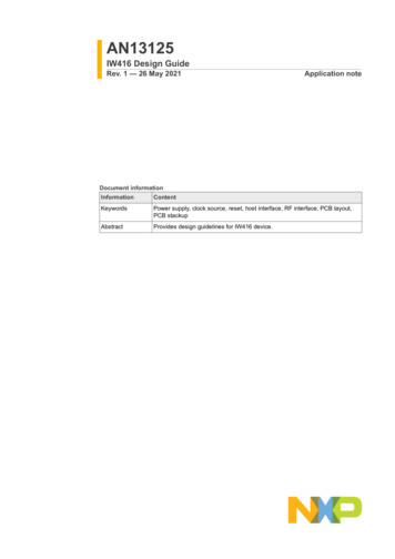
S32 Automotive Computing PortfolioPowertrain &Vehicle DynamicsBody & ComfortVehicle Dynamics &SafetyGeneral Purpose &Integrated SolutionsChassis, Safety,Torque and EnergyManagementBody ElectronicsEdge NodesDriver ReplacementGatewayAdvanced DriverAssistance SystemsConnectivity &SecurityRadar, LIDAR, VisionSensor FusionVehicle NetworkProcessing Long term innovator in chassisand powertrain control Broadest portfolio of integratedMCU HV mixed-signal solutions #1 in radar processing SignificantMPC577growth in safety asS32Sautonomouscontrol drivesrobust fault tolerant systems Application S32Kspecific softwaresolutions S12Z Comprehensive radar,S32Rvision and centralS32Vprocessingportfolio #1 in vehicle networking andsecurityMPC574 End-to-end portfolio ofS32networking devicesCOMPANY PUBLIC12
Safety Targets for Next-Generation PlatformSensorprocessingASIL B to DNumbercrunchingASIL B to eloped as a Safety ElementOut of Context (SEooC)PerformanceCPUsDecisionASIL DReal-time CPUsProtectedI/OFollowing an ISO 26262 ASIL-DSafety Development ProcessSupported with ComplementarySafety CollateralCOMPANY PUBLIC13
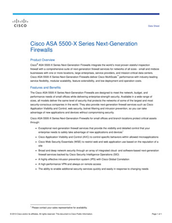
S32 HW Safety MeasuresDelayed Lockstep or DecoupledPerformance Clusters, INT CTLECC on memories.Lockstep DMA with ECC onmemories & integrated CRCDelayed Lockstep Real-time Cores &INT CTL.ECC on MUDMADMAL2 CacheL2 CacheTo SoC IslandInterconnect: Replicated Master& Slave NIUs Parity on allmessages Fault Reporting BISTeXtended ResourceDomain Controllermanages accesscontrol, systemmemory protectionand RDCxRDCDRAMHSCommsECC onDRAMRedundantPeripheralsSafety oreCoreMPUMPUMPUMPUTCMTCML1 CacheL1 CacheCoherent BusMain BusPeripheral ersSTCUADCADCxRDCxRDCFCCUEIMRCCURGMSbSWCMUCRCFault Collector UnitError Injection ManagerError Recovery ManagerReset GenerationManagerSafety by SoftwareMemory BusSRAMECC on SRAMClock MonitoringPower Supply MonitoringLogic & MemoryBuilt-in Self TestCOMPANY PUBLICxRDC14
Fault Management and AvailabilityReset/Power-upPrevious Generation – Stateof the Art Functional SafetyS32x – Introducing availability2019 Lockstep mismatch MCU resetLockstep mismatch beginavailability flowNo localization of fault beyondlockstep core pairLocalization of fault possible toindividual coreNo continued operation possiblewith safety coverageNot possible to distinguishbetween permanent and transientfaults in core complexIn LockstepFaultSafe State &completetransactionsContinued operation possible with lossof core, or loss of clusterTransient FaultRemaining core/cluster functionalRecoveryModeAll transient faults recoverableCache faults recoverable without BIST– reset onlyRestartPermanent FaultFail Safe StrategyFault Tolerant StrategyDegraded 0Degraded 1COMPANY PUBLICShutdown15
Top Level Safety Requirements The SoC itself is developed as a SEooC to provide functionaly with appropriateassumed safety integrity – ASIL D Fault Tolerant Time Interval (time a Fault occurrence and the system transitions to aSafe state) FTTIMCU 10ms to 100msMultiple Point Fault Detection Interval (multi-point faults are latent faults) SPFM (Single Point Failure Metric): 99% for transient & permanent faultsLFM (Latent Failure Metric): 90% for permanent faultsPMHF (Probabilistic Metric Hardware Failure): 10-9 h-1 (10% of system target for ASIL-D ( 10-8 h-1))MPFDIMCU defined by application (e.g. 12hrs typical auto)To detect multiple-point faults in the most critical safety mechanisms, softwareinitiated fault injection tests can be periodically triggered within the FTTI.COMPANY PUBLIC16
Top Level Availability Requirements The contribution of the SoC to the Fault Recovery Time of theapplication is targeted to beFRT 50 ms. This time is split between fault recovery (FRTMCU) and reset/boot(BootTimeMCU) Note: This includes the time to perform SoC fault diagnostics, reset and boot the SoC to thepoint to handover to load full application code. It does not include the application reinitialization time.Fault Tolerance (Availability) of the SoC is targeted to be: 100 FIT (10-7 h-1) of failures should lead to application ShutdownCOMPANY PUBLIC17
Fault Reactions – FCCU When a fault is routed to the FCCU there are 3 reactions possible tobring the SoC to a safe state: R1:Alarm interrupt with FCCU timer, if timer expires interrupt and error out asserted(local recovery) R2: Interrupt and error out asserted (global recovery) R3: No interrupt, error out asserted and reset (no recovery configured) If a fault is Not Safety Related, the FCCU could be configured to thefollowing reactions: Faultis disabled, no FCCU reaction InterruptCOMPANY PUBLIC18
S32 Automotive PlatformSafety SW and ToolsCOMPANY PUBLIC19
Safety Software Support (Safety SDK)Safety SDKSafety SDKCustomer ApplicationSafety BootSupportRecoverySupportSafety SDKRuntime Detection and Reaction SupportBISTEIMS32 SoCFCCURGMERM Successful boot of safety-related components is required to start a safety application. Runtime fault detection is mediated by Safety SDK – faults are detected by both HW andSW mechanisms Runtime error recovery is managed via Safety SDK Safety SDK manages a global, destructive SoC recovery.COMPANY PUBLIC20
Safety SDK ComponentsDetection Components SquareCheck – detects latent faultsin HW safety mechanismBIST Manager – configures, initiates,and provides access to MBIST andLBISTsBoot – detects violations of HWsafety configurationsCRCU – detects faults in CRC;also, it computes CRCReaction Components eMCEM – Error Managerconfigures FCCU and provideshandlers to faults signaled toFCCUSW Recovery – initiates theglobal recovery processMode Selector – depending onthe SoC fault status selects theappropriate operating modeCOMPANY PUBLIC21
Safety Software PortfolioSafety SDKFunctionalSafety LayerServiceSafety LayerHW SafetyLayerAutosar sMCALsCRCURecovery SWSbSWsBootSquareCheckMBIST & LBISTManagerSCSTLBISTNXPSoCMode SelectorSafety Device ConfigeMCEMApplication SDKMBISTSTCUERMFCCUCMUHW SafetyMeasuresPTLibPerf CPUPerf CPUSRAMWDGSafety bySW – HW IPRadar AcceleratorRT CPURT CPUFlashControllerComputational ShellVison AcceleratorGPUCommunication& IO PeripheralsVision, RadarPeripheralsCOMPANY PUBLIC22
SW Safety DeliverablesNPI CRFPRSystem RS/AS/System Safety ConceptNPI Safety Manual3-8.5.16-5.5.1/7.5.26-6.5.3Software Safety ConceptISO26262 ConfirmationMeasuresFSA2 (Detailed Design)FSA1 (Safety Concept)PCFSA1, FSA2, FSA3Confirmation ReviewSW Safety PlanAudit/AssessmentSW Safety Case6-7.5.4/7.5.5/8-8.5.1SW FMEA2-6.5.4/6/5/58-11.5.1/11.5.2Safety CaseSafety CaseSafety CaseSW FMEASW FMEASW FMEASafety ManualSafety ManualSafety ManualSafety Assessment PlanSW Tools Evaluation & Qualification ReportsFSA3 (Final Product)Automotive SPICE Safety Extensions ISO 26262COMPANY PUBLIC23
Tool erators Classification Report Qualification Plan Qualification Report Safety Manual ISO26262 compliance reportCertifiedCompilers (3P)PerformanceCPUsReal-time CPUsValidas AGCOMPANY PUBLIC24
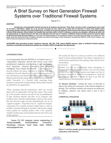
S32 Safety Alternatives for Performance CoresHW LockstepSafety by SWCore Self TestTA1Core 2Core 0TA2TA3Core 3TMCCore 1TMWDPCore 0L2Core 1Core 2Core 3Core 0Core 1Core 2Core 3SCSTSCSTSCSTSCSTL2L2L2L2 Targets ASIL D Delayed Lock-step Clusters Configured at Boot Fully transparent to SW Fallback to degraded mode in case of apermanent faultL2 Enable ASIL B/D by applicationmonitoring Targets ASIL B (with minimal SWoverhead) Detects loss of integrity and data errorcaused by SW & HW faults Core self-test (SCST) Time Monitored Comparator (TMC)– Detects data and timing errors Executed @ runtime on each CPU Timed Multi-Watchdog Processor(TMWDP)– Operational logical flow errorsHigh diagnostic coverage with lowperformance impactCOMPANY PUBLIC25
Getting Safety SupportCOMPANY PUBLIC26
SafeAssure CommunityCustomer Support for Functional SafetySafeAssure CommunitySafeAssure NDAPublic Space for knowledgedistribution and industry-wide newsherePrivate NDA space for customer toaccess safety documentationhereSupportSafety Expert Group composed ofSafety Managers and Architects, Fieldand Application EngineersSelf SufficientCommunity users find answers to their questions an safety documentation requestsCOMPANY PUBLIC27
NXP ISO 26262 Confirmation MeasuresNXP performs ISO 26262 Confirmation Reviews (CR), Audit and Assessment as required by ISO 26262 for SEooC developmentConfirmationMeasuresASIL AASIL BASIL CASIL DCR Safety AnalysisYesYesYesYesCR Safety PlanYesYesYesCR Safety CaseYesYesYesCR Software ToolsYesYesAuditYesYesAssessmentYesYesNote: The following confirmation reviews are not applicable: hazard analysis and risk assessment,item integration and testing, validation plan & proven in use argumentConfirmation Measures (CM) performed depending on ASIL All checks executed with independence level I3 by NXP Quality organization NXP Assessors certified by SGS-TÜV Saar as Automotive Functional Safety Professional (AFSP) NXP CM process certified by SGS-TÜV Saar as ISO 26262 ASIL DCOMPANY PUBLIC28
NXP SafeAssure ProductsTo support the customer to build their safety system, the followingdeliverables are provided as standard for all ISO 26262 developed products Public Information available via NXP Website Quality Certificates Reference Manual Data SheetConfidential Information available under NDA Safety Plan Safety Manual Permanent Failure Rate data (Die & Package) - IEC/TR 62380 orSN29500 Transient Failure Rate data (Die) - JEDEC Standard JESD89 Safety Analysis (FMEDA, FTA, DFA) & Report PPAP Confirmation Measures Report (summary of all applicable confirmationmeasures)COMPANY PUBLIC29
NXP and the NXP logo are trademarks of NXP B.V. All other product or service names are the property of their respective owners. 2019 NXP B.V.
Vehicle Network Processing #1 in vehicle networking and security End-to-end portfolio of networking devices . Driver Replacement. Advanced Driver Assistance Systems. Radar, LIDAR, Vision. Sensor Fusion #1 in radar processing Comprehensive radar, vision and central processing portfolio MPC577. S32S. S32K. S12Z. S32R. S32V. MPC574 .