Transcription
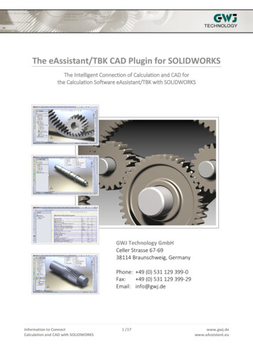
The eAssistant/TBK CAD Plugin for SOLIDWORKSThe Intelligent Connection of Calculation and CAD forthe Calculation Software eAssistant/TBK with SOLIDWORKSGWJ Technology GmbHCeller Strasse 67-6938114 Braunschweig, GermanyPhone: 49 (0) 531 129 399-0Fax: 49 (0) 531 129 399-29Email: info@gwj.deInformation to ConnectCalculation and CAD with SOLIDWORKS1 /17www.gwj.dewww.eAssistant.eu
Contents1. Installation.32. Start.33. Program Scope.34. Menu.4Calculation.4New Part.5User Data (applies only for eAssistant).6Options.7Language.8Help.85. Create a Shaft.96. Create a Cylindrical Gear.97. Create a Gearing on an Existing Part.108. Add Manufacturing Data to Engineering Drawing.119. Open a Calculation of an Active Part.1210. Add a Tool Runout to the 3D Model.1311. Bidirectional Connection between eAssistant/TBK and SOLIDWORKS.1312. Create a Shaft in SOLIDWORKS and Import it into eAssistant/TBK.15Information to ConnectCalculation and CAD with SOLIDWORKS2 /17www.gwj.dewww.eAssistant.eu
1. InstallationPlease start the installation file and follow the instructions. The CAD plugin will be installed onyour system. Select "eAssistant" or "TBK" during installation depending on the product. Once theCAD plugin is installed, start SOLIDWORKS and open a new part. The Tools drop-down menu inthe SOLIDWORKS menu bar provides the entry "eAssistant" or "TBK".In case the CAD plugin is not visible in the SOLIDWORKS Tools drop-down menu, you must enablethe eAssistant/TBK add-in application. Click Tools Add-Ins from the SOLIDWORKS menu barand activate the eAssistant/TBK application.2. StartClick the Tools drop-down menu to use all functions of the CAD plugin in SOLIDWORKS.3. Program ScopeCurrently, the following features can be created in SOLIDWORKS based on the calculatedeAssistant/TBK data:External and internal cylindrical and helical gearsRack/pinion gear pairsStraight, helical and spiral bevel gearsInformation to ConnectCalculation and CAD with SOLIDWORKS3 /17www.gwj.dewww.eAssistant.eu
Serrated shafts, splined shaft connections (shaft/hub)Solid and hollow shafts with an unlimited number of cylindrical and conical shaft segmentsInvolute splines (shaft/hub)as well:Saving of calculation data in the 3D modelPlacing manufacturing data of cylindrical gears, bevel gears and involute splines onthe manufacturing drawingCylindrical gears can be created directly on an existing part.Bidirectional connection between eAssistant/TBK and SOLIDWORKS (shaft, gear, involutespline profile as single design component) (from SOLIDWORKS 2008)Accuracy/point distance for the tooth form can be defined in the options menu.Tooth flanks as splines or alternatively as arcs for cylindrical gears and involute toothprofiles possible4. MenuCalculationOnce the CAD plugin is started, all eAssistant/TBK calculation modules can be opened directlythrough the Calculation menu in SOLIDWORKS.Note on eAssistant: Please note that you need an eAssistant username and password tostart the calculation modules through the Calculation menu (see Settings ). Only thefree-of-charge modules can be used without the eAssistant access data.Information to ConnectCalculation and CAD with SOLIDWORKS4 /17www.gwj.dewww.eAssistant.eu
New PartBased on the eAssistant/TBK calculation, the parts can be created directly in SOLIDWORKS byclicking the menu item New part .Complete a calculation using the eAssistant/TBK. Click on the button CAD SOLIDWORKS outputin the top menu bar of the eAssistant/TBK. Confirm the message "Data for CAD was writtensuccessfully." with the button "OK".During the generation of involute gearings (cylindrical gears, single cylindrical gears, gearracks, involute splines), the mean tooth thickness allowances and the mean tip diameterallowances should be selected. The CAD model is then created with these allowances.You can modify the allowances by opening the mask Tooth form in the respective gearmodules.Information to ConnectCalculation and CAD with SOLIDWORKS5 /17www.gwj.dewww.eAssistant.eu
Then click the menu item New part in the CAD plugin and select the corresponding element. Nowthe 3D model is created.User Data (applies only for eAssistant)Click on the menu item Tools eAssistant Settings User data to enter your eAssistantusername and your password. You need an account to use all eAssistant calculation modules.In case you do not have an eAssistant account, please visit our web site www.eAssistant.eu toregister for a free test account. Click on the button Request access data to get to the eAssistantweb site as well. The account provides a time credit of five hours to test the eAssistant withoutany charges or obligation. Are the five hours expired, the test account is deactivated automatically. If you want continue to use the eAssistant, you need to purchase an account. Decidebetween hour packages or flat rates.As soon as you entered your username and password into the window, you can start all eAssistantcalculation modules directly through the menu item Tools eAssistant Calculation withoutlogging in again. The eAssistant and SOLIDWORKS will be connected automatically.Information to ConnectCalculation and CAD with SOLIDWORKS6 /17www.gwj.dewww.eAssistant.eu
Activate the option "Save data permanent" to save your username and password andto open all calculation modules immediately without entering username and passwordagain.OptionsClick the menu item Tools eAssistant (TBK) Settings Options to adjust different settingsfor cylindrical and bevel gears. Select spline or arcs (tangential) to connect the points.You can, for example, define the distance between the points (accuracy) or the number of teethto be generated. Just activate the checkbox and enter the appropriate number of teeth.Information to ConnectCalculation and CAD with SOLIDWORKS7 /17www.gwj.dewww.eAssistant.eu
LanguageClick the menu item Tools eAssistant (TBK) Settings Language in order to change thelanguage. German and English are available. Restart SOLIDWORKS or the CAD plugin (by clickingTools Add-Ins ). The menu interface of the CAD plugin adapts itself automatically to the selectedlanguage. The eAssistant/TBK calculation modules are started in the selected language as well.HelpClick on the menu item Tools eAssistant (TBK) Help eAssistant (TBK) help online to openthe eAssistant/TBK manual where you can find additional information on the eAssistant/TBK.Information to ConnectCalculation and CAD with SOLIDWORKS8 /17www.gwj.dewww.eAssistant.eu
5. Create a ShaftBased on the eAssistant/TBK calculation, shafts with an unlimited number of cylindrical andconical segments can be created as a 3D part. Click on the menu item Tools eAssistant (TBK) Calculation Shaft to start the eAssistant/TBK module. Then make a shaft calculation. Clickon the button CAD SOLIDWORKS export in the eAssistant/TBK module. Create the shaft byclicking on the menu item Tools eAssistant/TBK New part Shaft to create the shaft inSOLIDWORKS.You can also create a 2D sketch of a shaft in SOLIDWORKS and then import it toeAssistant/TBK. Please see Section 12 for more information.6. Create a Cylindrical GearClick on the menu item Tools eAssistant (TBK) Calculation Gears Cylindrical gear pairin order to start the eAssistant/TBK calculation module. Then make a calculation. Click on thebutton CAD SOLIDWORKS export in the eAssistant/TBK module. Click on the menu itemTools eAssistant (TBK) New part Cylindrical gears Cylindrical gear 1 or cylindrical gear2, 3, 4 to create the cylindrical gear in SOLIDWORKS.Information to ConnectCalculation and CAD with SOLIDWORKS9 /17www.gwj.dewww.eAssistant.eu
7. Create a Gearing on an Existing PartThe eAssistant/TBK plugin provides a simple way to create a gearing directly on an existing part(pinion shaft).Make a gear calculation in the eAssistant/TBK. Click on the button CAD SOLIDWORKS export .Select a front face where you want to place the gearing. The face will then be highlighted. Selectthe menu item Tools eAssistant/TBK New part Cylindrical gears Cylindrical gear 1 toadd the gearing to the existing part.Information to ConnectCalculation and CAD with SOLIDWORKS10 /17www.gwj.dewww.eAssistant.eu
When the dialog window for the "Runout configuration" appears, confirm with the "OK" button.Please note that the tip circle diameter of the cylindrical gear gear and the diameter ofthe selected shaft segment must have the same size.8. Add Manufacturing Data to Engineering DrawingWith just one click, the design table with all manufacturing details can be placed on themanufacturing drawing. Open a drawing in SOLIDWORKS. Select the menu item Tools Assistant (TBK) Manufacturing data from selected view or from current calculation Cylindrical gear 1 to create the table.After installation of the CAD plugin, the file "Manufacturingdata.xml" appears in the programdirectory. When calling the manufacturing data via the CAD plugin, a new folder is created in thedirectory C:\User\[Username]\AppData\Roaming on Windows Vista or Windows 7. Varioustemplates (for example "ManufacturingdataBG.xml") for the design tables are saved in this folderand only these xml files are used to configure the table. Based on these files, the design table canbe modified to your preferences.Cylindrical gears, bevel gears and involute splines get a template as soon as you call the manufacturing data. For bevel gears, a distinction is made between straight/helical bevel gears andspiral bevel gears. The appearance and size of that table are both individually configurable. Openthe xml file in a text editor and change the corresponding row, for example from visible "true"into visible "false" to show or hide specific table rows. Save the xml file and place it to themanufacturing drawing. In case you need more extensive customizations (font size, column width,etc.) of the table, please ask for a more detailed description.Information to ConnectCalculation and CAD with SOLIDWORKS11 /17www.gwj.dewww.eAssistant.eu
If you delete the folder "eAssistant" in the user directory, the templates (xml files) aredeleted, too. To avoid this, please create a backup of the folder.In case the path C:\User\[Username]\AppData\Roaming is not displayed, the folder options mustbe adjusted. Open the folder options by clicking Start Control panel Folder options . Clickthe View tab. Select "Show hidden files, folders, and drives" under "Hidden files and folders". Click"OK" to save the new setting.The modifications of the xml files will be lost after an update of the CAD plugin. You haveto subsequently maintain the modifications manually.9. Open a Calculation of an Active PartThe calculation information is saved in the 3D model. The calculation, which belongs to the 3Dmodel, can be opened at any time throughout the entire design phase. If a component containsseveral different calculation elements, it is possible to open the corresponding calculations.To start the calculation, which belongs to the opened 3D model, click on the menu item Tools eAssistant (TBK) Calculation and select the corresponding calculation module. The followingdialog window appears. Click the "Yes" button and the eAssistant/TBK opens the calculationmodule with all calculation values.Even if there are several different gear calculations in one 3D model, you can open everycalculation file again. For the gear, for example, click on the feature tree on the left side inSOLIDWORKS to select the corresponding cutout. Click on the menu item Tools eAssistant(TBK) Calculation and then click on the calculation module.Information to ConnectCalculation and CAD with SOLIDWORKS12 /17www.gwj.dewww.eAssistant.eu
10. Add a Tool Runout to the 3D ModelFor pinion shafts you can add a tool runout to the 3D model. For this purpose, you have to specifya cutter radius. Select the menu item Tools eAssistant (TBK) Calculation Gears Cylindrical gear pair and run a cylindrical gear calculation. Click the button CAD SOLIDWORKSexport . Choose a plane of the shaft in SOLIDWORKS and click the menu item Tools eAssistant(TBK) New part Cylindrical gears Cylindrical gear 1 . The dialog window is opened.Activate the option "Yes" for "Run-out at start" or "Run-out at end". Add a cutter radius andconfirm with "OK".Now you can check if the tool runout collides with the following shaft segment, so that you cancorrect it. If necessary, you can add a straight element by using the option "Offset".11. Bidirectional Connection between eAssistant/TBK and SOLIDWORKSThe attractiveness of the CAD plugin is additionally enhanced by the bidirectional connectionbetween eAssistant/TBK and SOLIDWORKS. As changes are made to a calculation, the 3D modelcan be updated (shafts, cylindrical gear, or involute spline profile/hub profile as single part).Select the menu item Tools eAssistant (TBK) Calculation Gears Cylindrical gear pairand make a cylindrical gear calculation. Click the button CAD SOLIDWORKS export to transferthe calculation values to SOLIDWORKS. Click the SOLIDWORKS menu item Tools eAssistant(TBK) New part Cylindrical gears Cylindrical gear 1 to create the cylindrical gear.Information to ConnectCalculation and CAD with SOLIDWORKS13 /17www.gwj.dewww.eAssistant.eu
To make necessary changes on the CAD model, re-open the eAssistant/TBK module and modifythe calculation. Because the calculation information is saved to the CAD model, you can start theeAssistant/TBK calculation by clicking Tools eAssistant Calculation Gears Cylindricalgear pair . Confirm the following message "Shall the calculation of the active part be loaded?"with the button "Yes" and the related calculation module starts.For example, you can add a hole to gear 1. Click on the button CAD SOLIDWORKS export .Select the item "Extrusion2" from the integrated SOLIDWORKS feature tree. The area betweenthe teeth will then be highlighted.Select Tools eAssistant (TBK) New part Cylindrical gears Cylindrical gear 1 and themessage "Should the component be adjusted to the current calculation?" appears.Information to ConnectCalculation and CAD with SOLIDWORKS14 /17www.gwj.dewww.eAssistant.eu
Click the "Yes" button and the CAD model is updated immediately and quickly adjusted to thecurrent calculation.12. Create a Shaft in SOLIDWORKS and Import it into eAssistant/TBKYou can create a shaft directly in SOLIDWORKS and then import it into eAssistant/TBK. Solid andhollow shafts with cylindrical and conical shaft segments are possible. To create a shaft as arevolved part, use the CAD s revolve features, the inner shaft geometry can be generated usingthe revolved cut feature.Information to ConnectCalculation and CAD with SOLIDWORKS15 /17www.gwj.dewww.eAssistant.eu
To create a shaft as a revolved part, use the SOLIDWORKS Revolve Feature . Select the corresponding feature(s) from the FeatureManager design tree and import the shaft intoeAssistant/TBK by clicking the menu item Tools eAssistant (TBK) Calculation Shafts .The eAssistant/TBK shaft module opens and the shaft is loaded into the calculation module.Information to ConnectCalculation and CAD with SOLIDWORKS16 /17www.gwj.dewww.eAssistant.eu
We are looking for ideas, suggestions or criticism, so we wouldlike to know what you think.You will always find a sympathetic ear, no matter what the problem is.We appreciate your feedback.GWJ Technology GmbHCeller Strasse 67-6938114 Braunschweig, GermanyPhone: 49 (0) 531 129 399-0Fax: 49 (0) 531 129 399-29Email: info@gwj.deVisit our web site www.eAssistant.eu and www.tbksoft.com to find detailedinformation or videos on the eAssistant/TBK software and the 3D CAD plugin.Product information:eAssistant and TBK are products of GWJ Technology GmbH.Information to ConnectCalculation and CAD with SOLIDWORKS17 /17www.gwj.dewww.eAssistant.euCopyright GWJ Technology GmbH. Copyright reserved. All other brand names, product names or trademarks belong to their respective holders. Changes and errors reserved.
the eAssistant/TBK add-in application. Click Tools Add-Ins from the SOLIDWORKS menu bar and activate the eAssistant/TBK application. 2.Start Click the Tools drop-down menu to use all functions of the CAD plugin in SOLIDWORKS. 3.Program Scope Currently, the following features can be created in SOLIDWORKS based on the calculated