Transcription
1550 MBSModbus Protocol Interface1550 Communications Interface for 1336Adjustable Frequency AC DriveUser ManualFebruary 16, 2005
Please Read This NoticeSuccessful application of this module requires a reasonable working knowledge of the AllenBradley Modbus Protocol Interface 1550 Communications Interface for 1336 Adjustable FrequencyAC Drive hardware and the application in which the combination is to be used. For this reason, it isimportant that those responsible for implementation satisfy themselves that the combination willmeet the needs of the application without exposing personnel or equipment to unsafe orinappropriate working conditions.This manual is provided to assist the user. Every attempt has been made to assure that theinformation provided is accurate and a true reflection of the product's installation requirements. Inorder to assure a complete understanding of the operation of the product, the user should read allapplicable Allen Bradley documentation on the operation of the Allen Bradley hardware.Under no conditions will ProSoft Technology, Inc. be responsible or liable for indirect orconsequential damages resulting from the use or application of the product.Reproduction of the contents of this manual, in whole or in part, without written permission fromProSoft Technology, Inc. is prohibited.Information in this manual is subject to change without notice and does not represent acommitment on the part of ProSoft Technology, Inc. Improvements and/or changes in this manualor the product may be made at any time. These changes will be made periodically to correcttechnical inaccuracies or typographical errors.Important Notice: The 1550 card allows remote access to commands inthe Allen Bradley drives and other SCANport compatible devices. Theuser is responsible for assuring that any applicable regulationsconcerning the remote operation of equipment are adhered to.Your Feedback PleaseWe always want you to feel that you made the right decision to use our products. If you havesuggestions, comments, compliments or complaints about the product, documentation or support,please write or call us.ProSoft Technology, Inc.1675 Chester Avenue, Second FloorBakersfield, CA 93301(661) 716-5100(661) 716-5101 (Fax)http://www.prosoft-technology.comCopyright ProSoft Technology, Inc. 2000 - 2005. All Rights Reserved.1550 MBS User ManualFebruary 16, 2005
Contents1550 MBS Modbus Protocol Interface1550 Communications Interface for 1336 Adjustable Frequency AC DriveContentsPLEASE READ THIS NOTICE.2Your Feedback Please .21QUICK START GUIDE .51.12PRODUCT SPECIFICATIONS.72.1Read/Write.72.1.2Read Only.7Modbus Communications .113.1.1Command/Reply Cycle.113.1.2Command Types .113.1.3Command Error Checking.123.1.4Data Integrity .123.1.5Modbus Register Map .12HARDWARE SETUP.154.15General Specifications .8SLAVE PORT FUNCTIONALITY.113.14Modbus Slave Specifications .72.1.12.23Step-by-Step .51550 Card Setup .154.1.1Connecting Power to the 1550 Card - Enclosed Style .154.1.2Dip Switch Configuration .15CONFIGURING DRIVE PARAMETERS .195.1Data Transfer .195.1.1Controlling Drive Frequency.195.1.2Setting up the Adaptor I/O - Data Out .205.1.3Setting up the Adaptor I/O - Data In .20ProSoft Technology, Inc.February 16, 2005Page 3 of 45
1550 MBS Modbus Protocol Interface1550 Communications Interface for 1336 Adjustable Frequency AC Drive67ContentsTROUBLESHOOTING. 216.1LED Locations . 216.2LED Troubleshooting Table . 22CABLE DIAGRAMS . 237.11550 Communication Port . 23APPENDIX A MODBUS REGISTER MAP . 25APPENDIX B DEVICE SPECIFIC HINTS. 27SMC Dialogue Plus . 27SMP 3 27APPENDIX C: MOUNTING INSTRUCTIONS—OPEN AND ENCLOSED STYLE UNITS . 29Mounting the Communications Module . 29Enclosed Style Communications . 31APPENDIX D: CABLE REQUIREMENTS. 351305 Drive . 351336 PLUS (7.5-500HP) and 1336 FORCE. 36SMP 3 36APPENDIX E: SCANPORT DATALINK OPERATION . 39SUPPORT, SERVICE & WARRANTY. 41Support, Service and Warranty . 41Module Service and Repair . 41General Warranty Policy . 42Limitation of Liability. 42Hardware Product Warranty Details . 43INDEX. 45Page 4 of 45ProSoft Technology, Inc.February 16, 2005
Quick Start Guide11550 MBS Modbus Protocol Interface1550 Communications Interface for 1336 Adjustable Frequency AC DriveQuick Start GuideIn This Chapter¾Step-by-Step . 5In this section we have assembled a simple step-by-step procedure for installingand making the 1550 unit operational. This discussion presumes that theapplication decisions such as RS-232 versus RS-485, SCALper cable length, etc.have been addressed prior to this point.1.1Step-by-StepThe following steps will allow the 1550 to be setup in the shortest period of time(the following steps refer to the Allen Bradley drive implementation. Similar stepsare followed when interfacing to other A-B Power Division products):1Set the dip switches. The 1550 dip switch positions are detailed in Section 32Mount the 1550 either in the drive or on the DIN rail. If using an Open Style,plug the unit into the drive. If using the Enclosed Style, mount the unit withDIN rail. See Appendix C for mounting instructions.3Connect power to the 1550. If working with an Open Style unit, there are nopower connection concerns. When working with the 120 VAC or the 24 VDCEnclosed Style units, please refer to Section 34Setup the Drive hardware. Refer to the appropriate drive manual to connectcontrol and power to the drive. This aspect of the drive installation is out ofthe scope of this manual.5Setup the Drive parameters. See Section 4 of the manual to setup the driveparameters6Install the SCANport cable between the drive and the 1550. When using theEnclosed Style, a cable connection between the 1550 and the drive must bemade to connect the SCANports together. See Appendix D for instructions.7Connect the serial communication cable between the host system and the1550. Section 6 details the cable connection diagrams for RS-232, RS-422and RS-485 connections to the 1550 unit.ProSoft Technology, Inc.February 16, 2005Page 5 of 45
1550 MBS Modbus Protocol Interface1550 Communications Interface for 1336 Adjustable Frequency AC DrivePage 6 of 45Quick Start GuideProSoft Technology, Inc.February 16, 2005
Product Specifications21550 MBS Modbus Protocol Interface1550 Communications Interface for 1336 Adjustable Frequency AC DriveProduct SpecificationsIn This Chapter¾Modbus Slave Specifications . 7¾General Specifications . 8The ProSoft Technology, Inc. 1550-MBS card is a hardware product designed tobe a communications front end for Allen Bradley SCANport compatible products(1336 Plus/Force/Vector and 1305, SMC Dialogue Plus, SMP3, etc.).The product includes the following functionality:2.1Modbus Slave Specifications Protocol modes:RTU mode with CRC-16 error checking Supported Modbus Function codes:3Read Multiple Data Registers4Read Input Registers5Force Single Coil6Preset (Write) Single Data Register8Loopback Test (Test 0 only)16 Preset Multiple Data Registers (1 word per write) Supports broadcast commands from host Pre-assigned Modbus memory map2.1.1Read/Write Command Control/Frequency Datalinks Out A to D Up to 575 drive parameter values2.1.2Read Only Status/Feedback Datalinks In A to DProSoft Technology, Inc.February 16, 2005Page 7 of 45
1550 MBS Modbus Protocol InterfaceProduct Specifications1550 Communications Interface for 1336 Adjustable Frequency AC Drive2.2General Specifications Configuration via dip switchesSlave Address1 to 63Baud Rate300 to 19200 baudParityNone, Odd and EvenPhysical LinkRS-232, RS-422 or RS-485Stop Bits1 or 2Comm ConfigurationModbus RTU SlaveModbus ASCII 7 or 8 bit Slave (future)SCANport MessagingDatalink A Enable (Type 4 Enable)Datalink B Enable (Type 5 Enable)Datalink C Enable (Type 6 Enable)Datalink D Enable (Type 7 Enable) Supplied in two forms:Open Style - Power supplied by driveEnclosed - Power supplied externally (120 VAC) Communication Port ConnectorsModbus - 9 Pin FemaleSCANport - Regular A-B SCANport connection Status LEDSCANport Status (bi-color)Serial Port Status (bi-color)Tx/Tx Activity Status (amber) Current Consumption : 60 ma DC Input VoltageOpenSupplied by driveEnclosed85 to 264 VAC, 1 Phase45 to 63 HzPage 8 of 45ProSoft Technology, Inc.February 16, 2005
Product Specifications1550 MBS Modbus Protocol Interface1550 Communications Interface for 1336 Adjustable Frequency AC Drive Operating Temp 0 to 50 C Storage TempProSoft Technology, Inc.February 16, 2005-40 to 85 CPage 9 of 45
1550 MBS Modbus Protocol InterfaceProduct Specifications1550 Communications Interface for 1336 Adjustable Frequency AC DrivePage 10 of 45ProSoft Technology, Inc.February 16, 2005
Slave Port Functionality1550 MBS Modbus Protocol Interface1550 Communications Interface for 1336 Adjustable Frequency AC Drive3Slave Port FunctionalityIn This Chapter¾3.1Modbus Communications. 11Modbus CommunicationsThe 1550-MBS Modbus Slave card runs the RTU version of the Modbusprotocol. This capability allows the module to communicate data from a A-B VFDto a Modbus Master host, and vice-versa. The module supports both point-topoint implementations as well as multi-drop implementations.The following discusses the functional capabilities of the 1550-MBS card.3.1.1Command/Reply CycleSuccessful communications between the card and a host will always consist ofthe following two transactions:Command: Message from master giving instruction to slave.Reply: Response to command.A slave station will respond to a master issued command in several ways. Data Message: If the command was executed by the slave, the responsemessage will include the data requested, or an acknowledgment that thecommand was executed. Error Message: If the command could not be executed by the slave, forwhatever reason, an error response message is transmitted to the master.The error response message consists of the original function code (or'd with80hex) and an error code. No Reply: If the master does not detect a reply within its timeout period, themaster should re-transmit the command, before a time out error is issued. Ifthe Slave could not decode the message or an error occurred preventing theSlave from recognizing the message, no response will be issued.3.1.2Command TypesThe 1550-MBS can respond to three types of commands from the master; readdata, write data, and a diagnostic command. These are described below:Read Data:The following types of data read commands are supported:ProSoft Technology, Inc.February 16, 2005Page 11 of 45
1550 MBS Modbus Protocol InterfaceSlave Port Functionality1550 Communications Interface for 1336 Adjustable Frequency AC DriveCommandDescription3Read Multiple Registers4Read Input RegistersWrite Data:The following data write command is supported:CommandDescription5Force Single Coil6Single Register Write16Write Multiple RegistersDiagnostics: The diagnostic command is supported:CommandDescription8Loopback Test - Code 03.1.3Command Error CheckingWhen the 1550-MBS cannot execute a command, an error code is generatedand returned to the master. Error codes generated at the slave will usually beindicative of an illegal function, an illegal address, bad data, or the inability tocomplete a transaction because of a network problem.3.1.4Data IntegrityAs in all good protocols, there must exist a level of data integrity checking toverify, with some degree of assurance, the quality of the transmitted data. TheModbus protocol supports two types of error checking: RTU Mode : 16 bit cyclic redundancy check (CRC-16) One bit parity checkCRC-16: When the master generates a message, a 16 bit CRC value is added tothe end of the transmitted packet. The CRC value is generated using a series ofbit shifts and manipulations. The receiving station executes the same calculationon the data and verifies the transmitted CRC. Any discrepancy will cause themessage to be disregarded.Parity: Parity checking can be added as an additional level of data security. Ifparity checking is selected, even or odd parity can be implemented.3.1.5Modbus Register MapA pre-defined register map has been provided for the 1550 unit. This map isdetailed in Appendix A. The full memory map is dependent on the A-B devicewhich is connected to the 1550 unit.Page 12 of 45ProSoft Technology, Inc.February 16, 2005
Slave Port Functionality1550 MBS Modbus Protocol Interface1550 Communications Interface for 1336 Adjustable Frequency AC DriveOn power-up, the 1550 unit polls the remote device and determines the numberof parameters that exist. If the number is greater than 575 the parameter list willbe limited to 575.ProSoft Technology, Inc.February 16, 2005Page 13 of 45
1550 MBS Modbus Protocol InterfaceSlave Port Functionality1550 Communications Interface for 1336 Adjustable Frequency AC DrivePage 14 of 45ProSoft Technology, Inc.February 16, 2005
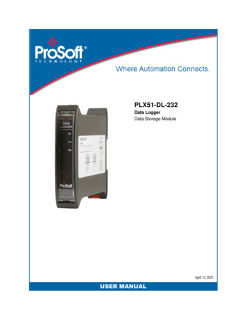
Hardware Setup41550 MBS Modbus Protocol Interface1550 Communications Interface for 1336 Adjustable Frequency AC DriveHardware SetupIn This Chapter¾4.11550 Card Setup . 151550 Card Setup4.1.1Connecting Power to the 1550 Card - Enclosed StyleConnecting power to the Enclosed Style Communication Module (1552 model)requires a simple termination of the 120 VAC cable to the front of the module.The connection is shown in the following diagram:4.1.2115 VAC HotL115 VAC NeutralNGroundGDip Switch ConfigurationConfiguration of the 1550 is independent of whether the unit is an internallymounted (1551) card or an externally mounted unit (1552). In either case,configuration consists of setting up some dip switches. The dip switches are asfollows:Please note that dip switch configuration is read by the 1550 during the power upprocess. Power must be cycled if dip switches are changed under power.ProSoft Technology, Inc.February 16, 2005Page 15 of 45
1550 MBS Modbus Protocol Interface1550 Communications Interface for 1336 Adjustable Frequency AC DriveHardware SetupSwitch SW 1Switch SW 2Page 16 of 45ProSoft Technology, Inc.February 16, 2005
Hardware Setup1550 MBS Modbus Protocol Interface1550 Communications Interface for 1336 Adjustable Frequency AC DriveSwitch SW 3ProSoft Technology, Inc.February 16, 2005Page 17 of 45
1550 MBS Modbus Protocol Interface1550 Communications Interface for 1336 Adjustable Frequency AC DrivePage 18 of 45Hardware SetupProSoft Technology, Inc.February 16, 2005
Configuring Drive Parameters1550 MBS Modbus Protocol Interface1550 Communications Interface for 1336 Adjustable Frequency AC Drive5Configuring Drive ParametersIn This Chapter¾Data Transfer . 19When the drive is first received, several parameters must be setup by the user inorder for data transfer and control to be properly implemented.5.1Data Transfer1The 1550 units read and write data using three methods:2Control/Status Read and Write by default (Type 2 command )3Datalinks A to D selected by dip switch (Type 4,5,6,7 commands)4Client/Server Messaging by default (Up to 575 parameters)When full datalinks ( A to D) are enabled , a total of 10 words of data can betransferred each way. Two of these words are dedicated to specific functions,leaving eight words for User configuration.In order to accomplish the transfer, the A-B Device’s I/O ADAPTOR Data In andData Out parameters must be configured. A discussion on the SCANport linkcommunications is excerpted from the A-B documentation and included inAppendix D.Please note that not all A-B Scanport devices support Datalinks. In particular, theSMC Dialogue Plus does not. To operate with the SMC Dialogue Plus do notenable the Datalink Messaging.5.1.1Controlling Drive FrequencyThe primary configuration which must be performed is associated with enablingFrequency Control from the 1550.In order to enable Frequency control from the 1550, the drive parameterFREQUENCY SELECT 2 must be configured for the appropriate Adapter IDrepresenting the 1550 module. This will normally be Adaptor #2, unless aSCANport expander is being used (in which case this Adaptor number will bebased on the port the 1550 is plugged into.ProSoft Technology, Inc.February 16, 2005Page 19 of 45
1550 MBS Modbus Protocol InterfaceConfiguring Drive Parameters1550 Communications Interface for 1336 Adjustable Frequency AC Drive5.1.2Setting up the Adaptor I/O - Data OutSelects the parameter values which will be made available to the 1550 forreading into the register map. The Parameter Table can be found in Appendix Awhich details the placement of the values in the 1550.Data Out ImageSuggested ParameterDescriptionA154Output CurrentA21Output VoltsB123Output PowerB253DC Bus VoltageD119Maximum FrequencyD24Last FaultC1C25.1.3Setting up the Adaptor I/O - Data InSelects the parameters which will be made accessible for configuration/ writingfrom the 1550. As with the Data Out parameters, there are eight possibleselections. These may be chosen as needed to meet the needs of theapplication.Page 20 of 45ProSoft Technology, Inc.February 16, 2005
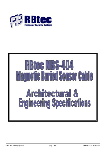
Troubleshooting61550 MBS Modbus Protocol Interface1550 Communications Interface for 1336 Adjustable Frequency AC DriveTroubleshootingIn This Chapter¾LED Locations. 21¾LED Troubleshooting Table . 22Several hardware diagnostics capabilities have been implemented using the LEDindicator lights on the front of the 1550 card. The possible conditions as indicatedby the lights are:6.1LED LocationsThe location of the LEDs on the units are shown in the following diagrams:RX ActiveSCANport StatusLNSerial Port StatusGTX ActiveLED Locations for Enclosed Style unitTX ActiveSerial Port StatusSW3SW2SW1SCANport StatusRX ActiveFront View Open VersionLED Locations for Open Style unitProSoft Technology, Inc.February 16, 2005Page 21 of 45
1550 MBS Modbus Protocol Interface1550 Communications Interface for 1336 Adjustable Frequency AC Drive6.2TroubleshootingLED Troubleshooting TableThe following table details the meaning of the LEDs in the 1550 unit.NAMEColorStatusIndicationSerial Port StatusGreenBlinkingThe 1550 has successfullyprocessed a command from thehost and has generated aresponse.RedSteady or Blinking The 1550 unit has detected aserial communication errorcondition on the Serial port. Thisis normally due to a badcommunication transmissionfrom a host such as an invalidcommand or a request for aninvalid point.This LED will also be steady ifSW3-4 is enabled and there isno communication on the serialport.SCANport StatusRX ActiveGreenSteadySCANport connection if OKGreenBlinkingCheck cable connections.Indicates that the 1550 unit is notable to link up with the drive’sSCANport. Make sure that the AB device supports Datalinks ifthe 1550 Datalinks are enabled.RedSteadyThe SCANport connection hasfaulted. Check configurationswitch settings, SCANport cableconnections, cycle power.Contact ProSoft factory supportif problem persists.AmberBlinkingThe 1550 Serial Port hasdetected some activity on thereceive pins.BlinkingThe 1550 is sending out aresponse to the host.orGreenTX ActiveAmberorGreenPage 22 of 45ProSoft Technology, Inc.February 16, 2005
Cable Diagrams71550 MBS Modbus Protocol Interface1550 Communications Interface for 1336 Adjustable Frequency AC DriveCable DiagramsIn This Chapter¾1550 Communication Port. 23The communication connections to the 1550 card are made via a DB-9 pinfemale connection on the front of the card. The physical terminations are shownin the following diagrams.7.11550 Communication PortRS-232 w/ No Hardware HandshakingPort Connection with anothercommunication portRS-422 4-wire ConnectionRS-485 2-wire ConnectionProSoft Technology, Inc.February 16, 20051550DB-9 Pin FemalePC or DeviceTxD2RxDRxD3TxDCOM5GND1550DB-9 Pin FemaleRS-422DeviceTxD 9RxD TxD-4RxD-RxD 6TxD RxD-2TxD-COM5COM(Optional)1550DB-9 Pin FemaleRS-485DeviceTxRxD 9TxRxD TxRxD-4TxRxD-COM5COMShield3Page 23 of 45
1550 MBS Modbus Protocol Interface1550 Communications Interface for 1336 Adjustable Frequency AC DrivePage 24 of 45Cable DiagramsProSoft Technology, Inc.February 16, 2005
Appendix A Modbus Register Map1550 MBS Modbus Protocol Interface1550 Communications Interface for 1336 Adjustable Frequency AC DriveAppendix A Modbus Register MapFCFCFCType543Reg BitDescriptionR/W1 to 16 30001400010Command Control WordR/W30002400021Type 2 - Word 2R/W30003400032Adaptor I/O - Out A1Type 4 CommandR/W30004400043Adaptor I/O - Out A2Type 4 CommandR/W30005400054Adaptor I/O - Out B1Type 5 CommandR/W30006400065Adaptor I/O - Out B2Type 5 CommandR/W30007400076Adaptor I/O - Out C1Type 6 CommandR/W30008400087Adaptor I/O - Out C2Type 6 CommandR/W30009400098Adaptor I/O - Out D1Type 7 CommandR/W30010400109Adaptor I/O - Out D2Type 7 CommandR300114001110Status WordR300124001211Type 2 - Word 2R300134001312Adaptor I/O - In A1Type 4 CommandR300144001413Adaptor I/O - In A2Type 4 CommandR300154001514Adaptor I/O - In B1Type 5 CommandR300164001615Adaptor I/O - In B2Type 5 CommandR300174001716Adaptor I/O - In C1Type 6 CommandR300184001817Adaptor I/O - In C2Type 6 CommandR300194001918Adaptor I/O - In D1Type 7 CommandR300204002019Adaptor I/O - In D2Type 7 CommandR300214002120ScanPort Comm StatusDevice Parameter 33R/W3002540025244R/W3002640026255R/W-R/WFC 3 Modbus Address Parameter Number 40021R/WR/W30xxx40xxxUp to Max Parameter in Device (Up to 575 max)All register values in the 1550-MBS are presented in unscaled units. Please referto the drive User manual for any necessary scaling informationProSoft Technology, Inc.February 16, 2005Page 25 of 45
1550 MBS Modbus Protocol InterfaceAppendix A Modbus Register Map1550 Communications Interface for 1336 Adjustable Frequency AC DrivePage 26 of 45ProSoft Technology, Inc.February 16, 2005
Appendix B Device Specific Hints1550 MBS Modbus Protocol Interface1550 Communications Interface for 1336 Adjustable Frequency AC DriveAppendix B Device Specific HintsSMC Dialogue PlusThe SMC Dialogue Plus does not support Datalinks, therefore the configurationof SW3 should not include any of the Datalinks Enabled. If a Datalink is enabled,the SCANport Status LED will toggle, indicating an error in the SCANportcommunications.The version of SMC which we tested (Rev 1.05) had 88 parameters. Eachparameter was accessible in the Modbus register listing shown in Appendix A.Note that if one of the 88 parameters is to be changed from a host that the hostmust enable the EEPROM Storage function by writing a 2 into the ParameterManagement parameter (17 - Modbus address 40038 ).SMP 3The SMP3 does not support Datalinks, therefore the configuration of SW3 shouldnot include any of the Datalinks Enabled. If a Datalink is enabled, the SCANportStatus LED will toggle, indicating an error in the SCANport communications.The 1550 is able to read all of the parameters out of the SMP3 unit.ProSoft Technology, Inc.February 16, 2005Page 27 of 45
1550 MBS Modbus Protocol InterfaceAppendix B Device Specific Hints1550 Communications Interface for 1336 Adjustable Frequency AC DrivePage 28 of 45ProSoft Technology, Inc.February 16, 2005
Appendix C: Mounting Instructions1550 MBS Modbus Protocol Interface1550 Communications Interface for 1336 Adjustable Frequency AC DriveAppendix C: Mounting InstructionsOpen and Enclosed Style UnitsIn This Chapter¾Mounting the Communications Module . 29¾Enclosed Style Communications. 31Mounting the Communications ModuleThe Communications Module can be provided in three mounting configurations Open style board, factory installed in a drive (not available for all drives)] Open style board as a separate kit Enclosed style for panel mount or DIN rail mountThis section provides mounting information for the Enclosed style and the Openstyle kit.ProSoft Technology, Inc.February 16, 2005Page 29 of 45
1550 MBS Modbus Protocol InterfaceAppendix C: Mounting Instructions1550 Communications Interface for 1336 Adjustable Frequency AC DriveFigure C-1Open Style Communications Module Mounting Location(1336 PLUS 7.5-500HP)Page 30 of 45ProSoft Technology, Inc.February 16, 2005
Appendix C: Mounting Instructions1550 MBS Modbus Protocol Interface1550 Communications Interface for 1336 Adjustable Frequency AC DriveEnclosed Style CommunicationsModule DimensionsFigure C-2Enclosed Style Communications Module DimensionsProSoft Technology, Inc.February 16, 2005Page 31 of 45
1550 MBS Modbus Protocol InterfaceAppendix C: Mounting Instructions1550 Communications Interface for 1336 Adjustable Frequency AC DrivePage 32 of 45ProSoft Technology, Inc.February 16, 2005
Appendix C: Mounting Instructions1550 MBS Modbus Protocol Interface1550 Communications Interface for 1336 Adjustable Frequency AC DriveFigure C-3Enclosed Style Communications Module Mounting Location(1336 FORCE Drive with Standard Adapter Board)ProSoft Technology, Inc.February 16, 2005Page 33 of 45
1550 MBS Modbus P
User Manual February 16, 2005 . Please Read This Notice . Quick Start Guide 1550 MBS Modbus Protocol Interface 1550 Communications Interface for 1336 Adjustable Frequency AC Drive . SMC Dialogue Plus, SMP3, etc.). The product includes the following functionality: