Transcription
PLX51-DL-232Data LoggerData Storage ModuleApril 13, 2021USER MANUAL
Your Feedback PleaseWe always want you to feel that you made the right decision to use our products. If you have suggestions, comments,compliments or complaints about our products, documentation, or support, please write or call us.ProSoft Technology, Inc. 1 (661) 716-5100 1 (661) 716-5101 hnology.comPLX51-DL-232 User ManualApril 13, 2021ProSoft Technology , is a registered copyright of ProSoft Technology, Inc. All other brand or product names are or may betrademarks of, and are used to identify products and services of, their respective owners.In an effort to conserve paper, ProSoft Technology no longer includes printed manuals with our product shipments. UserManuals, Datasheets, Sample Ladder Files, and Configuration Files are provided at our website:www.prosoft-technology.comContent DisclaimerThis documentation is not intended as a substitute for and is not to be used for determining suitability or reliability of theseproducts for specific user applications. It is the duty of any such user or integrator to perform the appropriate and complete riskanalysis, evaluation and testing of the products with respect to the relevant specific application or use thereof. Neither ProSoftTechnology nor any of its affiliates or subsidiaries shall be responsible or liable for misuse of the information contained herein.Information in this document including illustrations, specifications and dimensions may contain technical inaccuracies ortypographical errors. ProSoft Technology makes no warranty or representation as to its accuracy and assumes no liability forand reserves the right to correct such inaccuracies or errors at any time without notice. If you have any suggestions forimprovements or amendments or have found errors in this publication, please notify us.No part of this document may be reproduced in any form or by any means, electronic or mechanical, including photocopying,without express written permission of ProSoft Technology. All pertinent state, regional, and local safety regulations must beobserved when installing and using this product. For reasons of safety and to help ensure compliance with documented systemdata, only the manufacturer should perform repairs to components. When devices are used for applications with technicalsafety requirements, the relevant instructions must be followed. Failure to use ProSoft Technology software or approvedsoftware with our hardware products may result in injury, harm, or improper operating results. Failure to observe thisinformation can result in injury or equipment damage. 2021 ProSoft Technology. All Rights Reserved.Printed documentation is available for purchase. Contact ProSoft Technology for pricing and availability.For professional users in the European UnionIf you wish to discard electrical and electronic equipment (EEE), please contact your dealer or supplier for furtherinformation.Warning – Cancer and Reproductive Harm – www.P65Warnings.ca.govAgency Approvals and CertificationsPlease visit our website: www.prosoft-technology.comPage 2
CONTENTS1.2.3.Preface . 51.1.Introduction to the Data Logger . 51.2.Features . 61.3.Additional Information . 7Installation . 82.1.Module Layout . 82.2.Module Mounting . 102.3.Power . 112.4.RS232 Port . 112.5.Ethernet Port . 11Setup . 123.1.Install Configuration Software . 123.2.Network Parameters . 123.2.1.DHCP Server Settings . 123.2.2.Network Settings. 153.3.Creating a New Project. 173.4.Configuring the PLX51-DL-232 . 193.4.1.General Tab . 193.4.1.Serial Tab . 213.5.3.5.1.Group and Tag Triggers . 223.5.2.Logix Source . 233.5.3.DF1 Source . 263.5.4.Modbus Source . 273.6.4.Data Source Configuration . 22Module Download . 28RSLogix 5000 Configuration . 314.1.Add Module to I/O Configuration . 314.2.Importing UDT’s and Mapping Routines . 33Page 3
4.3.RSLogix 5000 assemblies . 364.3.1.5.6.7.8.Input Assembly. 37Diagnostics . 385.1.LEDs . 385.2.Module Status Monitoring . 395.2.1.General Tab . 415.2.2.Statistics tab . 425.2.3.Tag Status Tab . 435.2.4.Recent Records Tab . 445.2.5.Record Management Tab . 455.2.6.CIP Statistics Tab . 465.2.7.Ethernet Clients Tab. 475.2.8.TCP / ARP Tab. 485.3.DF1 Packet Capture . 495.4.Modbus Packet Capture . 525.5.Module Event Log. 555.6.Web Server . 56Technical Specifications . 576.1.Dimensions . 576.2.Electrical . 586.3.Ethernet. 586.4.Data Cache . 596.5.Serial Port . 596.6.DF1. 596.7.Modbus . 606.8.Agency Approvals & Certifications . 60Support, Service & Warranty . 617.1.Contacting Technical Support . 617.2.Warranty Information . 61Index. 62Page 4
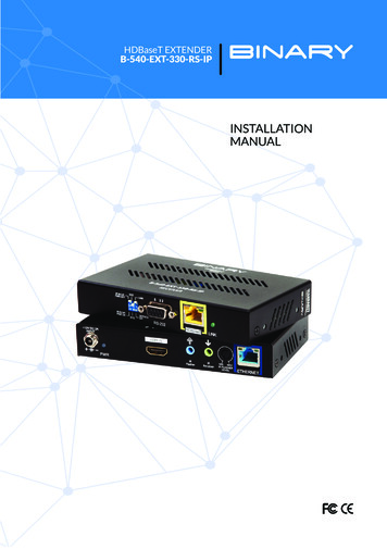
1. PREFACE1.1. INTRODUCTION TO THE DATA LOGGERThis manual describes the installation, configuration, operation, and diagnostics of the PLX51-DL232. The PLX51-DL-232 can read and store data from Logix Controllers, DF1 Serial Interfaces, orModbus devices. The PLX51-DL-232 has the capacity to store over 16 million records in its solidstate non-volatile memory. Each stored record includes a Date Time stamp with a 50 msresolution, Tag Name, Data Type, and Value.The PLX51-DL-232 can be used to log data at a remote site with limited communication with itsbase. The PLX51-DL-232 is also used to store records on mobile equipment such as trucks,drilling rigs, or snow plows. Once the equipment returns back to its base, the historical data canbe uploaded and transferred to a more permanent storage device. The PLX51-DL-232 can alsobe configured to collect data which is only downloaded and examined if a fault occurs,otherwise the data is overwritten.Figure 1.3. – Non-Historian OptionPage 5
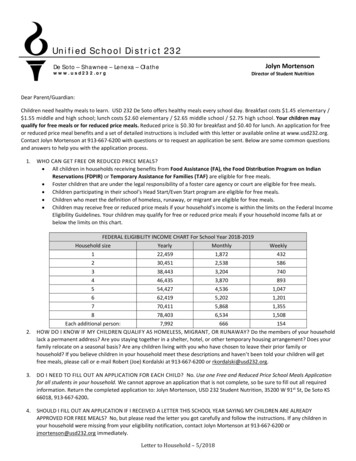
1.2. FEATURESThe PLX51-DL-232 provides temporary extensive on-board storage capability for storing processtags. A total of 16,777,216 records can be stored in its non-volatile memory.Each record consists of the following data:ParameterLinkDate TimeUTC Time includes: Year, Month, Day, Hour, Minute, Second, Milliseconds.Time has a resolution of 50 milliseconds.Tag NameAs defined in Controller or in the PLX50 Configuration Utility for other sourcesData TypeBOOL, SINT, INT, DINT, or REALValueLogix Tag / DF1 File / Modbus Register valueTable 1.1. – Components of a RecordThe Log Index is managed by the PLX51-DL-232 and incremented each time a new record isstored. The Unload Index is managed externally by the unload service. It is only incremented aftera record has been logged successfully to a text file. The records can be unloaded in Logix with theExample Code. Both the Log Index and Unload Indices loop around, eventually reaching the endof the cache. The cache becomes 100% full when the Log Index loops around and equals theUnload Index. In this situation, either older records are overwritten (Log Mode Overwrite) ornewer records are not logged (Log Mode Hold).Figure 1.4. - Memory SchematicPage 6
The PLX51-DL-232 is configured using the ProSoft PLX50 Configuration Utility. This program canbe downloaded from www.prosoft-technology.com, free of charge. The PLX50 ConfigurationUtility offers various configuration methods, including a controller tag browser. The PLX50Configuration Utility can also be used to monitor the status and download historical data to alocal file.The PLX51-DL-232 can operate in both a Logix “owned” and standalone mode. With a Logixconnection, the input and output assemblies provide additional diagnostics information. Thisinformation is available in the Logix controller environment.The PLX51-DL-232 uses isolated RS232 for DF1 communication. The RS232 port also uses aterminal block for convenient installation.A built-in webserver provides detailed diagnostics of system configuration and operation.1.3. ADDITIONAL INFORMATIONThe following documents contain additional information that can assist you with installation andoperation.ResourcePLX50 ConfigurationUtility InstallationUser ManualDatasheetExample Code & nology.comEthernet wiring e/cde205 220 420/installation/guide/cde205 220 420 hig/Connectors.htmlCIP RoutingThe CIP Networks Library, Volume 1, Appendix C:Data ManagementTable 1.2. - Additional InformationPage 7
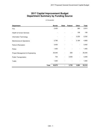
2. INSTALLATION2.1. MODULE LAYOUTThe PLX51-DL-232 has three ports at the bottom of the enclosure, as shown in the figure below.The ports are used for Ethernet, RS232 serial, and power.The DC power port uses a three-way connector ( positive, - negative, and Earth).The RS232 port uses a four-way connector (Tx Transmit, Rx Receive, Gnd Ground, and Shieldearth connection).The Ethernet cable must be wired according to industry standards which can be found in theadditional information section of this document.Figure 2.1. – Data Logger side and bottom viewPage 8
The PLX51-DL-232 provides three diagnostic LEDs (Ok, Act, and Eth). These LEDs provideinformation on system operation, the Ethernet interface, and the auxiliary communicationinterface (RS232).Figure 2.2. – Module front and top viewThe PLX51-DL-232 has four DIP switches at the top of the enclosure as shown above.DIP SwitchDescriptionDIP 1Used to force the PLX51-DL-232 into “Safe Mode”. When in “Safe Mode”, the PLX51DL-232 does not load the application firmware. It waits for new firmware to bedownloaded. This should only be used when a firmware update was interrupted at acritical stage.DIP 2Used to force the PLX51-DL-232 into DHCP mode, useful when the user has forgottenthe IP address of the PLX51-DL-232.DIP 3ReservedDIP 4ReservedTable 2.1. - DIP Switch SettingsPage 9
2.2. MODULE MOUNTINGThe PLX51-DL-232 provides a DIN rail clip to mount onto a 35mm DIN rail.Figure 2.3. - DIN rail specificationThe DIN rail clip is mounted on the bottom of the PLX51-DL-232. Use a flat screw driver to pullthe clip downward. Once the PLX51-DL-232 is mounted onto the DIN rail, the clip must be pushedupward to lock the PLX51-DL-232 in place.Figure 2.4. - DIN rail moutingPage 10
2.3. POWERA three-way power connector is used to connect positive, - negative, and Earth. The PLX51-DL232 requires an input voltage of 10 to 28 Vdc.Figure 2.5. - Power connector2.4. RS232 PORTThe RS232 connector is used to connect the Transmit (Tx), Receive (Rx), and Ground conductorsfor serial communication. The shield terminal can be used for shielded cable in high noiseenvironments.NOTE: The shield of the RS232 port is internally connected to the power connectorearth. Thus, when using a shield it is important to connect the Earth terminal onthe power connector to a clean earth. Failing to do this can lower the signal qualityof the RS232 communication.NOTE: When using a shielded cable, it is important that only one end of the shieldis connected to earth to avoid current loops. It is recommended to connect theshield to the PLX51-DL-232, and not to the other Serial device.Figure 2.6. - RS232 connector2.5. ETHERNET PORTThe Ethernet connector should be wired according to industry standards. Refer to the additionalinformation section in this document for further details.Page 11
3. SETUP3.1. INSTALL CONFIGURATION SOFTWAREThe PLX51-DL-232 is configured using the PLX50 Configuration Utility environment. This softwarecan be downloaded from www.prosoft-technology.com.Figure 3.1. - PLX50 Configuration Utility Environment3.2. NETWORK PARAMETERS3.2.1. DHCP SERVER SETTINGSBy default, the PLX51-DL-232 has DHCP (Dynamic Host Configuration Protocol) enabled. Thus, aDHCP server must be used to provide the PLX51-DL-232 with the required network parameters(IP address, subnet mask, etc.). There are a number of DHCP utilities available. However, it isrecommended to use the DHCP server in the PLX50 Configuration Utility.Page 12
1Within the PLX50 Configuration Utility, click on TOOLS DHCP SERVER.Figure 3.2. - Selecting DHCP Server2Once opened, the DHCP server listens on all available network adapters for DHCP requestsand displays their corresponding MAC addresses.Figure 3.3. - DHCP ServerNOTE: If the DHCP requests are not displayed in the DHCP Server, it may be dueto the local PC’s firewall. During installation, the necessary firewall rules areautomatically created for the Windows firewall. Another possibility is that anotherDHCP Server is operational on the network and it has assigned the IP address.Page 13
3To assign an IP address, click on the corresponding ASSIGN button. The Assign IP Addressdialog box opens.Figure 3.4. - Assigning IP AddressThe required IP address can then be either entered, or a recently used IP address can beselected by clicking on an item in the Recent list.If the Enable Static checkbox is checked, the IP address will be set to static after the IPassignment, thereby disabling future DHCP requests.4Click OK when complete.5Once the Assign IP Address dialog box has been accepted, the DHCP server automaticallyassigns the IP address to the PLX51-DL-232 and reads the Identity Object Product namefrom the device. The device indicates a green background upon successful assignment ofthe IP address.Figure 3.5. - Successful IP address assignmentPage 14
It is possible to force the PLX51-DL-232 into DHCP mode by powering up the device with DIPswitch 2 in the On position. A new IP address can then be assigned by repeating the previoussteps.NOTE: It is important to return DIP switch 2 back to Off position, to avoid thePLX51-DL-232 returning to a DHCP mode after the power is cycled again.In addition to the setting the IP address, other network parameters can be set during the DHCPprocess. These settings can be viewed and edited by clicking on TOOLS APPLICATION SETTINGS.3.2.2. NETWORK SETTINGSOnce the DHCP process has been completed, the network settings can be set using the EthernetPort Configuration via the Target Browser.1Click on TOOLS TARGET BROWSERFigure 3.6. - Selecting the Target Browser2The Target Browser automatically scans the Ethernet network for EtherNet/IP devices.Figure 3.7. - Target BrowserPage 15
3Right-clicking on a device reveals the context menu, including the Port Configurationoption.Figure 3.8. - Selecting Port Configuration4All relevant Ethernet port configuration parameters can be modified using the PortConfiguration dialog box.Figure 3.9. - Port ConfigurationAlternatively, these parameters can be modified using the Rockwell Automation RSLinx software.Page 16
3.3. CREATING A NEW PROJECTBefore you configure the PLX51-DL-232, a new PLX50 Configuration Utility project must becreated.1Click on FILE NEW.Figure 3.10. - Creating a new project2A new project is created and displayed in the Project Explorer tree view.3Add a new device by clicking on DEVICE ADD.Figure 3.11 - Adding a new devicePage 17
4In the Add New Device dialog box, select the PLX51-DL-232 and click the Ok button.Figure 3.12 – Selecting a new PLX51-DL-2325The device appears in the Project Explorer tree, and its configuration window is opened.The device configuration window can also be opened by double-clicking the PLX51-DL232 icon in the Project Explorer tree, or right-clicking the PLX51-DL-232 icon and selectingConfiguration.Figure 3.13 – PLX51-DL-232 configurationPage 18
3.4. CONFIGURING THE PLX51-DL-232The PLX51-DL-232 is configured by the PLX50 Configuration Utility. The configuration consists ofa general configuration, serial configuration for DF1 or Modbus RTU, data source configuration,and tag selections. The PLX51-DL-232 configuration is saved in non-volatile memory that persistswhen the PLX51-DL-232 is powered down.NOTE: When a firmware upgrade is performed, the PLX51-DL-232 will clear allconfiguration and cached records.3.4.1. GENERAL TABThe general configuration is shown in the figure below. The general configuration window isopened by either double-clicking on the PLX51-DL-232 icon in the tree, or right-clicking thePLX51-DL-232 icon and selecting Configuration.Figure 3.14 - General Configuration (Data Logger)Page 19
The general configuration consists of the following parameters:ParameterDescriptionInstance NameThis parameter is a user defined name to identify between various PLX51-DL-232’s.DescriptionThis parameter is used to provide a more detailed description of the PLX51-DL-232.Major RevisionThe major revision of the PLX51-DL-232.IP AddressThe PLX51-DL-232’s IP address used by the PLX50 Configuration Utility tocommunicate with the PLX51-DL-232.Data SourceThis parameter selects the source of the data.Logix – Rockwell Automation ControlLogix or Compact Logix controllerDF1 – Serial DF1ModbusRTU – Serial ModbusModbusTCP – Modbus over EthernetLogging ModeThis parameter determines if records are overwritten once the memory is filled.Overwrite Old records are overwritten, giving priority to newer data.Hold Old records are preserved while new records are not stored.Table 3.1 - General configuration parametersPage 20
3.4.1. SERIAL TABThe Serial tab is shown in the figure below. The Serial configuration is opened by either doubleclicking on the PLX51-DL-232 icon in the tree, or right-clicking the PLX51-DL-232 icon andselecting Configuration. Select the Serial tab.Figure 3.15 - Serial configurationThe Serial configuration (Serial tab) consists of general Serial and DF1-specific parameters. ForModbus RTU, only the Baud Rate and Parity need be configured.ParameterDescriptionBaud RateThis configures the speed of the data that is sent across the RS232 serial network.The PLX51-DL-232 provides the following speeds:1200, 2400, 4800, 9600, 19200, 38400, 57600, and 115200ParityThis configures the parity of the RS232 serial port. The PLX51-DL-232 allows forEven, Odd, or None.ProtocolThis configures the PLX51-DL-232 to operate in full duplex or half duplex modeon the DF1 network.Error DetectionThe PLX51-DL-232 can be configured to perform either BCC or CRC checksumvalidation on incoming and outgoing packets. CRC checksums is a much strongervalidation method, but is more processor-intensive to perform.Embedded ResponseThis configures the PLX51-DL-232 to add the acknowledge responses in the datapayload. It can be configured to be Auto Detect or On.This function is only available in Full Duplex mode.Page 21
Node AddressThe node address is the local node address of the PLX51-DL-232.Retry LimitThis determines how many times the PLX51-DL-232 must retry and messageexchange before failing it.TimeoutThis determines the interval between retries for a failed message exchange.Reply Msg WaitThis is the minimum delay before the DF1 reply is transmitted to the DF1 device.Duplicate DetectionThis configures the PLX51-DL-232 to check for duplicate packets and flaggingthem.Table 3.2 - Serial ModbusRTU and DF1 configuration parameters3.5. DATA SOURCE CONFIGURATIONThe Data Source tabs determine the PLX51-DL-232 communication mode used to acquire data.The Data Source options include: Logix Source – ControlLogix and Compact Logix controllers DF1 Source – For collecting data over DF1 Serial communications Modbus Source – for ModbusRTU (Serial) and ModbusTCP (Ethernet) communicationsOnce the data source is selected, each tab allows the configuration of up to three source devicesand a total of 200 tags.Tags can be logged as a result of their individual log criteria or via a group trigger. There are eighttrigger groups (A thru H), and a tag can be a member of any trigger group. Groups are in turntriggered by one or more tags. The triggering of a group ensures all its member’s values arelogged at the same instance.3.5.1. GROUP AND TAG TRIGGERSThree parameters determine when a tag is triggered: Delta Y (Δy) – A change in the value of the tag by this amount or more, AND Min ΔT – The minimum time in seconds between each consecutive trigger, OR Max ΔT – The maximum time between each consecutive trigger. Setting the Max ΔT to ‘0’disables the “heartbeat” and allows you to log on trigger.Page 22
The first two parameters work together to ensure tags are not logged too frequently, and theMax ΔT is set at a minimum logging frequency.Figure 3.17 – Group and Tag Triggers3.5.2. LOGIX SOURCEThe Logix Source tab is used to configure tags from Rockwell Automation Logix controllers overEtherNet/IP. The PLX51-DL-232 can read tags from up to three separate controllers. A TargetName must be provided. This acts as a reference to the Logix CIP path. The Target Name doesnot have to match the actual controller name set in RSLogix. The Controller’s CIP Path can eitherbe typed in or selected from a list in the Target Browser.Figure 3.20 – Logix Source Configuration TabPage 23
1Click the BROWSE button in the browse column to launch the Target Browser. The TargetBrowser opens and automatically scans for all available EtherNet/IP devices.Figure 3.21 – Target Browser Window2If the Ethernet/IP module is a bridge module, it can be expanded by right-clicking on thePLX51-DL-232 icon and selecting the Scan option.Figure 3.22 - Scanning node in the Target BrowserPage 24
3The Logix controller can be selected by clicking the Ok button, or by double-clicking onthe controller module.4Once the controller references have been configured, the individual Logix tags can beadded. Tags can either be entered manually or selected by using the Tag Browserassociated with each controller.Figure 3.23 - Logix Tag configurationNOTE: Tag names need to match in order for the PLX51-DL-232 to correctly identifythe tag. Full tag names are needed for tags to be located in program scopes.5To launch the Tag Browser, click the BROWSE TAGS button associated with the controller.Tags that are were already selected and identified are highlighted in green. See Fig 3.24.Figure 3.24 – Tag Browser SelectionPage 25
6Tags can be removed by selecting the rows in the left margin, and right-clicking to displaythe DELETE option.Figure 3.25 – Deleting Tags3.5.3. DF1 SOURCEA maximum of three DF1 Sources can be configured. The configuration of each source requires aDevice Name (used as a reference for tag data sources), the Device Type (either PLC5 or SLC), anda Node Address.Each DF1 Tag requires a unique Tagname and Data Address.Figure 3.26 – DF1 Source configurationPage 26
3.5.4. MODBUS SOURCEBoth Modbus RTU and Modbus TCP/IP are configured using the Modbus Source tab. For ModbusRTU, a maximum of three Modbus sources can be configured. The configuration of each sourcerequires a Device Name (used as a reference for tag data sources), the IP Address (Modbus TCP/IPonly), and a Node Address.Fig 3.27 – Modbus Source ConfigurationPage 27
3.6. MODULE DOWNLOADOnce the configuration is complete, it must be downloaded to the PLX51-DL-232.Before downloading, the connection path of the PLX51-DL-232 should be set. This pathautomatically defaults to the PLX51-DL-232 IP address, as set in the PLX51-DL-232 configuration.It can be modified if the PLX51-DL-232 is not on a local network.1The connection path can be set by right-clicking on the PLX51-DL-232 icon and selectingthe Connection Path option.Figure 3.28 - Selecting Connection Path2The new connection path can be entered manually or selected by means of the TargetBrowser.Figure 3.29 - Connection PathPage 28
3To initiate the download, right-click on the PLX51-DL-232 icon and select Download.Figure 3.30 - Selecting Download4Once complete, you will be notified that the download was successful.Figure 3.31 - Successful download5During the download process, the PLX51-DL-232’s time will be compared to that of thePC’s time. Should the difference be greater than 30 seconds, you will be prompted toset the PLX51-DL-232 time to that of the PC time.Figure 3.32 – Setting module timePage 29
6The PLX51-DL-232 time is used only for the event log. Within the PLX50 ConfigurationUtility environment, the PLX51-DL-232 will be in the Online state, indicated by the greencircle around the PLX51-DL-232 icon.Figure 3.33 - Module Online7The PLX51-DL-2
The PLX51-DL-232 is configured using the ProSoft PLX50 Configuration Utility. This program can be downloaded from www.prosoft-technology.com, free of charge. The PLX50 Configuration Utility offers various configuration methods, including a controller tag browser. The PLX50