Transcription
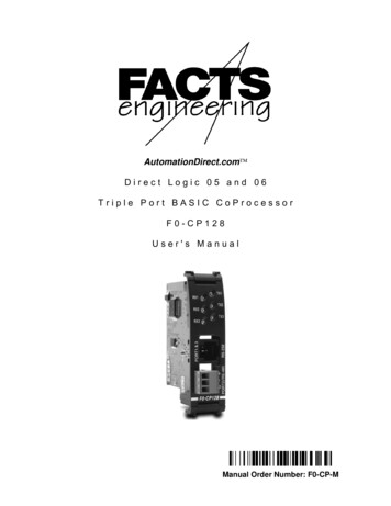
AutomationDirect.com Direct Logic 05 and 06Triple Port BASIC CoProcessorF0-CP128User's ManualManual Order Number: F0-CP-M
TRADEMARKS Automationdirect.com is a Trademark of Automationdirect.com CoProcessor is a Trademark of FACTS Engineering, Inc.COPYRIGHTCopyright 2004, FACTS Engineering Inc., 8049 Photonics Dr., New Port Richey,Florida, 34655. World rights reserved.Last Issued Date: September 2005Current Issued Date: August 2010
WARNINGThank you for purchasing automation equipment from FACTS Engineering. We wantyour new FACTS Engineering automation equipment to operate safely. Anyone whoinstalls or uses this equipment should read this publication (and any other relevantpublications) before installing or operating the equipment.To minimize the risk of potential safety problems, you should follow all applicable localand national codes that regulate the installation and operation of your equipment.These codes vary from area to area and usually change with time. It is yourresponsibility to determine which codes should be followed, and to verify that theequipment, installation, and operation is in compliance with the latest revision of thesecodes.At a minimum, you should follow all applicable sections of the National Fire Code,National Electrical Code, and the codes of the National Electrical ManufacturersAssociation (NEMA). There may be local regulatory or government offices that can helpdetermine which codes and standards are necessary for safe installation and operation.Equipment damage or serious injury to personnel can result from the failure to follow allapplicable codes and standards. We do not guarantee the products described in thispublication are suitable for your particular application, nor do we assume anyresponsibility for your product design, installation, or operation.If you have any questions concerning the installation or operation of this equipment, or ifyou need additional information, please call us at 1-800-783-3225.This document is based on information available at the time of its publication. Whileefforts have been made to be accurate, the information contained herein does notpurport to cover all details or variations in hardware and software, nor to provide forevery possible contingency in connection with installation, operation, and maintenance.Features may be described herein which are not present in all hardware and softwaresystems. FACTS Engineering assumes no obligation of notice to holders of thisdocument with respect to changes subsequently made. FACTS Engineering retains theright to make changes to hardware and software at any time, without notice. FACTSEngineering makes no representation or warranty, expressed, implied, or statutory withrespect to, and assumes no responsibility for the accuracy, completeness, sufficiency,or usefulness of the information contained herein. No warranties of merchantability offitness for purpose shall apply.
MANUAL HISTORYRefer to this history in all correspondence and/or discussion of this manual.Title: Direct Logic 05 and 06 Triple Port BASIC CoProcessors User’s ManualPart Number F0-CP-MIssue / DatePrelim 2/2005Prelim 8/2005Prelim 9/2005First 9/2005August 2010Effective PagesFront 1917,199,11,14,17Description of ChangesFirst DraftAdded B&W PictureVarious Corrections and Removed references toCOMMAND@2Misc CorrectionsFirst Edition – CorrectionsRemoved references to ONPLC
TABLE OF CONTENTSCHAPTER 1 : INTRODUCTION . 9CPU SYNCHRONIZATION. 9COMMAND@. 10CHAPTER 2 : COPROCESSOR STATEMENTS . 11BMOVE . 11IEEE Floating Point . 11Octal numbering and data types for BMOVE operands . 12DL05 BMOVE Operands . 12DL06 BMOVE Operands . 12DPORT. 14IEEE Floating Point . 14S06 . 17IEEE Floating Point . 17Octal numbering and data types for S06 operands . 18DL05 CPU S06 Operands. 18DL06 CPU S06 Operands. 18CHAPTER 3 : F0-CP128 Triple Port OverDrive CoProcessor . 20F0-CP128 GENERAL SPECIFICATIONS . 20F0-CP128 DESCRIPTION . 21F0-CP128 JUMPER DESCRIPTION AND LOCATION. 22CLR ALL . 22F0-CP128 PORT PINOUTS . 23PORT SPLITTER PINOUTS . 24APPENDIX A : QUICK START. 26INITIAL MODULE OPERATION USING ABM COMMANDER PLUS . 26EDITING A PROGRAM . 27SAVING A PROGRAM . 28AUTO RUN MODE. 29DELETING A PROGRAM. 29CANCEL AUTO RUN MODE . 30CHANGING THE PROGRAMMING PORT . 30APPENDIX B : TROUBLE SHOOTING. 32UNABLE TO ESTABLISH COMMUNICATION WITH BASIC COPROCESSOR . 32APPENDIX C : RS-232 AND RS-485 WIRING DIAGRAMS . 34RS-232 STANDARD . 34RS-232 DTE and DCE Pin Names and Signal Flow . 34IBM COMPUTER (PC) CABLES. 35RS-232 WITH HARDWARE HANDSHAKE . 36RS-485 STANDARD . 38RS-485 COMMUNICATION. 38RS-485 POINT-TO-POINT CABLING . 38RS-485 TWO WIRE MULTI-DROP. 39Cable Shielding . 40Connecting Cables and Line Termination . 40
CHAPTER 1 : INTRODUCTIONThis manual describes details specific to the 05 and 06 BASIC CoProcessor. This document should beused to supplement the FACTS Extended BASIC User's Reference (FA-BASIC-M) when programming theFACTS Engineering 05 and 06 CoProcessor modules.05 and 06 CoProcessor modules are installed in the expansion slot of a D0-05 brick or in any of the fourexpansion slots in a D0-06 brick.The CoProcessor module communicates to the DL05 or DL06 PLC CPU using the S06 , BMOVE, andDPORT instructions. A high speed dual port RAM interface, across the parallel bus of the DL05 or DL06backplane, is used for CoProcessor to PLC and PLC to CoProcessor communications. Up to 256 bytescan be transferred by the CoProcessor in one PLC scan using the BMOVE instruction. No PLC ladderlogic is required for CoProcessor to PLC or PLC to CoProcessor communications. The CoProcessor doesnot take any X's or Y's from the PLC CPU's memory map.The CoProcessor module communicates to external devices using the built in serial port(s).CPU SYNCHRONIZATIONUpon application of power the CoProcessor resets and establishes communication with the DL05 or DL06PLC CPU. Next the operating mode saved by the last AUTOSTART command is executed. Please seeAUTOSTART in the FACTS Extended BASIC User's Reference for additional information.The CoProcessor does not reset when the PLC CPU is out of RUN mode. If desired, the current state ofthe PLC CPU may be determined by examining Special Purpose relays SP11-20. See Chapter 2(CoProcessor Statements) for a description of the S06 statement. See the DL05 or DL06 User's Manualfor a description of PLC CPU special relays.Example10203040506070IF S06 SP(11) THEN PRINT "Forced running state"IF S06 SP(12) THEN PRINT "TERM RUN state"IF S06 SP(13) THEN PRINT "TEST RUN state"IF S06 SP(15) THEN PRINT "TEST PGM state"IF S06 SP(16) THEN PRINT "TERM PGM state"IF S06 SP(17) THEN PRINT "Forced STOP state"IF S06 SP(20) THEN PRINT "PGM Mode"Often a CPU control relay or stage status is used as a permissive in the BASIC program. Control relaysand stage status bits are used to communicate program status information to the CoProcessor. Forexample, a control relay may be used to signal the start of a shift report or to simply indicate that the PLCCPU is running.Example10 IF S06 C(0) THEN PRINT "CR 0 Energized"20 IF S06 SG(10) THEN PRINT "Stage 10 is active"CHAPTER 19
COMMAND@FunctionSelects the programming portSyntaxCOMMAND@ portUsageport is either 1 or 3 and specifies the programming/command port. BASIC sends allmessages to and accepts only COMMANDs from the specified port.The factory default programming/command port is Port 1 at 9600 baud.Use the SETPORT statement to change the power-up baud rate of any of the serial ports.Use COMMAND@ to debug communications with an external device connected toanother port. COMMAND@ can be used to get complete utilization of both ports whileminimizing the need for cable swapping or the use of switch boxes.ExampleAssume the program for a diagnostic/shift report printer connected to Port 3 has beencompleted. Now it is desired to operate a stepper motor controller using Port 1. To beginprogramming the stepper: SETPORT 3, 9600 COMMAND@3Sets the baud rate for Port 3Programming port is now Port 3Move the programming device cable from Port 1 to Port 3. A cable splitter is include forthis purpose.To go back to programming at Port 1, enter COMMAND@110INTRODUCTION
CHAPTER 2 : COPROCESSOR STATEMENTSBMOVEFunctionDirectly access a block of DL05 or DL06 CPU memorySyntaxBMOVE direction, starting operand(number), ending operand(number)BMOVE direction, starting operand(number), K (number of bytes)See AlsoDPORT and S06UsageUp to 256 bytes of DL05 or DL06 memory may be read or written in one scan usingBMOVE. Memory in the PLC CPU is referenced using any one of 11 different operandsspecified with an octal address number.Block move begins in the CoProcessor at dual port memory location DPORT(0) and in thePLC CPU at starting operand(number). The block move continues through consecutivememory addresses up to and including ending operand(number). Alternately, the numberof bytes to transfer may be specified as an expression in parenthesis following "K". Ifnumber of bytes is 0 then 256 bytes will be copied.Use either a "R" or "W" for direction to specify a PLC CPU memory Read or Write. "R"will read PLC CPU memory and copy to DPORT memory. "W" will read DPORT memoryand copy to PLC CPU V-memory.If starting operand or ending operand is a BIT data type, the entire V-Memory addresscontaining the operand is used.IEEE Floating PointNumeric Variables in the CoProcessor module are stored internally as a floating pointvalue in the range of 1E-127 to .99999999E 127. The PLC CPU can store numbers asa BCD, BINary, or as an IEEE floating point value in the range of 3.402822E 38. If youare using IEEE floating point values in the PLC and you want to operate on those valuesin the CoProcessor module use BMOVE and DPORT with the R portion or S06 VR.CHAPTER 211
Octal numbering and data types for BMOVE operandsDL05 BMOVE OperandsDescriptionOperandQtyOctal numberingData TypeV-Memory OctalWordTimer CurrentCount moryVolatileNon-volatileSystem nputsOutputsInternal RelaysStage StatusTimer StatusCounter StatusSpecial Relays (Read 140-4114741200-41237DescriptionOperandQtyOctal numberingData TypeV-Memory OctalWordTimer CurrentCount 7770-3770-1770-37770-37770-777HEX orBCD orFloat1200-73777400-75777600-7777DL06 BMOVE OperandsNon-volatileSystem ParametersInputsOutputsInternal RelaysStage StatusTimer StatusCounter StatusRemote I/OSpecial Relays (Read Only)12XYCSGTSCSGXGYSPCOPROCESSOR STATEMENTSHEX orBCD 1741140-4114740000-4017740200-4037741200-41237
ExampleLoad a table of 6 constants into user V-Memory starting at V200010 REM Load the table into dual port memory20 DPORT(0) 10H30 DPORT(2) 20H40 DPORT(4) 25H50 DPORT(6) 30H60 DPORT(8) 100H70 DPORT(10) 9798H80 REM Copy the table to PLC CPU V-Memory90 BMOVE W, VH(2000), K(12)ExampleMultiply a range of user V-Memory by a constant value10 BMOVE R, VH(2000), K(32) : REM Get the values20 REM Multiply by 2.530 FOR ADDR 0 TO 31 STEP 240 DPORT(ADDR) DPORT(ADDR)*2.550 NEXT ADDR60 BMOVE W, VH(2000), K(32) : REM Put the values backExampleGet the DL240 X (Input) image table10 BMOVE R, X(0), X(477)AdvancedIf no operand is specified then address number is the hexadecimal representation of theOctal V-Memory address (7FH Octal V-Memory 177). BMOVE R, VH(2000), K(10) isthe same as BMOVE R, (400H), K(10).This feature simplifies FOR-NEXT loops and other types of "calculated" PLC memoryaccesses.ExampleFind all user V-Memory locations which match a constant10 K 1234 : REM Match value15 REM Search V-Memory V2000-V777720 FOR INDEX 400H TO 1000H STEP 127 : REM 2 BYTES/V-MEM30 BMOVE R, (INDEX), K(127)40 FOR ADDR 0 TO 125 STEP 250 IF DPORT(ADDR) K THEN 7060 PRINT1 "Matched at V-Memory hex address ",62 PRINT1 HEX (INDEX ADDR)70 NEXT ADDR80 NEXT INDEXCHAPTER 213
DPORTFunctionRead or write memory shared with the DL05 or DL06 PLCsSyntaxDPORT (address, portion) expressionvariable DPORT (address, portion)UsageDPORT (dual port memory) is used in conjunction with the BMOVE (block move)statement to access the PLC CPU.The DPORT operator retrieves the value at the dual port memory address and assigns itto the variable.The DPORT statement stores the value of expression at the dual port memory address.address is an expression from 0 to 516, which selects two bytes of dual port memory.DPORT retrieves or assigns an integer value (0 to 65535) at address.portion is optional and is used to specify a bit position, a nibble (group of 4 bits), a byte(group of 8 bits), a BCD word (2 bytes), or an IEEE Floating Point value (4 bytes).Use "B(n)" to specify one of 16 bit positions, where n 0-15.Use "N(n)" to specify one of four nibbles, where n 0-3.Use "H" to specify the high byte or use "L" to specify the low byte.Use "B" to specify a word hexadecimal to BCD conversion.Use “R” to specify a BASIC Floating Point to IEEE Floating Point conversion.The first 256 bytes of dual port memory, DPORT(0) to DPORT(255), are used by theBMOVE statement when reading from or writing data to the PLC.IEEE Floating PointNumeric Variables in the CoProcessor module are stored internally as a floating pointvalue in the range of 1E-127 to .99999999E 127. The PLC CPU can store numbers asa BCD, BINary, or as an IEEE floating point value in the range of 3.402822E 38. If youare using IEEE floating point values in the PLC and you want to operate on those valuesin the CoProcessor module use BMOVE and DPORT with the R portion or S06 VR.14COPROCESSOR STATEMENTS
ExampleRetrieve a 4 digit BCD (0-9999) value from dual port memory10 REM Put a BCD number at V-Memory 200020 S06 VB(2000) 123430 REM Get it back with a block move40 BMOVE R, VH(2000), K(2)50 PRINT1 "BCD value at V-Memory 2000 ",52 PRINT1 HEX (DPORT(0))NOTE: Use DirectSoft DataView and BCD/HEX display format to view BCD data in thePLC.ExampleStore 8 digit BCD (0-99999999) values in V-Memory 2000 and 2001 using BMOVE10 DPORT(0) 1234H : REM Constant for V-Memory 200020 A 5678 : REM A Must be a BCD value from 0 - 999930 DPORT(2) VAL(“0” STR (A) ”H”) : REM Same as DPORT(2,B) A40 BMOVE W, VH(2000), VH(2001)NOTE: Use DirectSoft DataView and BCD/HEX display format to view BCD data in thePLC.ExampleRetrieve a Hex/Integer (0-FFFFH/0-65535d) value from dual port memory102030405052REM Put a Hex/Decimal number at V-Memory 2000S06 VH(2000) 1234REM Get it back with a block moveBMOVE R, VH(2000), K(2)PRINT1 "Integer value at V-Memory 2000 ",PRINT1 HEX (DPORT(0))NOTE: Use DirectSoft DataView and Decimal display format to view Integer data in thePLC.ExampleStore a PLC Floating Point value then retrieve a value10 REM Write a Float Value to V1400/1401 and Read a Float from V1410/141120 DPORT(0,R) 3.402822E 3830 BMOVE W,VH(1400),K(4) : REM Floats use 2 words/4 bytes40 BMOVE R,VH(1410),K(4) : REM Floats use 2 words/4 bytes50 X DPORT(0,R)NOTE: Use DirectSoft DataView and Real or Exponential display format to view IEEEFloating Point data in the PLC.CHAPTER 215
ExampleUsing DPORT with PICK statement type modifiers1000 V 1120H1010 DPORT(0) V : PRINT1 "Retrieving values from DPORT"1020 PH1. "DPORT(0) ",V," in hexadecimal"1030 PRINT1 "1st nibble ",DPORT(0,N(0)), SPC (5),1040 PRINT1 "3rd nibble ",DPORT(0,N(2))1050 PRINT1 "DPORT(0) in binary "; : FOR BT 15 TO 0 STEP -11060 IF DPORT(0,B(BT)) THEN PRINT1 "1"; ELSE PRINT1 "0";1070 NEXT BT : PRINT11080 PH1. DPORT(0),1090 PRINT1 " or ",V," treated as BCD ",DPORT(0,B)," decimal"1100 HB DPORT(0,H) : REM Swap the bytes1110 DPORT(0,H) DPORT(0,L) : DPORT(0,L) HB1120 PH1. "Value with bytes swapped ",DPORT(0)1130 PRINT1 : PRINT1 "Assigning bits and nibbles in DPORT"1140 DPORT(0) 01150 FOR BT 0 TO 151160 DPORT(0,B(BT)) 11170 IF BT 8 THEN PRINT11180 PH1. DPORT(0), SPC (3),1190 NEXT : PRINT11200 DPORT(0) 01210 FOR N 0 TO 31220 DPORT(0,N(N)) 0FH1230 PH1. DPORT(0), SPC (3),1240 NEXT : PRINT11250 PRINT1 "BCD ASSIGNMENT"1260 DPORT(0,B) 11201270 PH1. DPORT(0)," 1120"READY runRetrieving values from DPORTDPORT(0) 1120H in hexadecimal1st nibble 0 3rd nibble 1DPORT(0) in binary 00010001001000001120H or 4384 treated as BCD 1120 decimalValue with bytes swapped 2011HAssigning bits and nibbles in DPORT0001H 0003H 0007H 000FH 001FH 003FH 007FH 00FFH01FFH 03FFH 07FFH 0FFFH 1FFFH 3FFFH 7FFFH FFFFH000FH 00FFH 0FFFH FFFFHBCD ASSIGNMENT1120H 112016COPROCESSOR STATEMENTS
S06FunctionDirectly access PLC CPU memorySyntaxS06 operand(number) expressionvariable S06 operand(number)ShorthandS. operand(number)See AlsoBMOVE and DPORTUsagePLC CPU memory may be accessed directly each scan using any one of 12 differentoperands specified with an octal address number.The S06 statement moves the value of expression into the PLC CPU memory addressspecified by operand(number). If the memory address is written to by the PLC CPUladder program, the S06 statement will be overridden.The S06 operator copies the value from the PLC CPU memory address specified byoperand(number) into a numeric variable.S06 values will be BCD (VB), HEXadecimal (VH), BIT (X,Y,C etc.) or IEEE FloatingPoint (VR) data types depending on the operand used. Discrete operands such as I/Opoints and control relays operate on bits and return logical values. Timer and counteraccumulated values are in BCD.The table below specifies the octal numbering and data types for each of the S06operands (typical VB and VH operand usage is shown).IEEE Floating PointNumeric Variables in the CoProcessor module are stored internally as a floating pointvalue in the range of 1E-127 to .99999999E 127. The PLC CPU can store numbers asa BCD, BINary, or as an IEEE floating point value in the range of 3.402822E 38. If youare using IEEE floating point values in the PLC CPU and you want to operate on thosevalues in the CoProcessor module use BMOVE and DPORT with the R portion orS06 VR.CHAPTER 217
Octal numbering and data types for S06 operandsDL05 CPU S06 OperandsDescriptionOperandQtyOctal numberingData TypeV-Memory OctalWordTimer CurrentCount moryVolatileNon-volatileSystem 777InputsOutputsInternal RelaysStage StatusTimer StatusCounter StatusSpecial Relays (Read 140-4114741200-41237DescriptionOperandQtyOctal numberingData TypeV-Memory OctalWordTimer CurrentCount 70-17770-3770-1770-37770-37770-777HEX orBCD orFloat1200-73777400-75777600-7777DL06 CPU S06 OperandsNon-volatileSystem ParametersInputsOutputsInternal RelaysStage StatusTimer StatusCounter StatusRemote I/OSpecial Relays (Read Only)18XYCSGTSCSGXGYSPCOPROCESSOR STATEMENTSHEX orBCD 1741140-4114740000-4017740200-4037741200-41237
ExampleUsing bit data type operands:10 REM Display status on Input X420 IF S06 X(4) THEN PRINT1 "ON" ELSE PRINT1 "OFF"10 REM Turn ON PLC CPU internal Control Relay C40020 S06 C(400) 110 REM Output Y23 OFF if CT2 is ON and X17 is OFF20 IF S06 CS(2).AND.NOT(S06 X(17)) THEN S06 Y(23) 0ExampleUsing BCD data type operands:10 REM Display current count for CNT C10 and TMRF T020 PRINT1 "Counter 10 ",S06 CT(10)30 PRINT1 "Timer 0 ",S06 T(0)/10010 REM Divide the current count of CNT C7 by 220 S06 CT(7) S06 CT(7)/210 REM Value from Analog Input is in V-Memory 200020 REM V-Memory 2001 gets the value for an Analog Out30 REM Keep the Analog Out proportional to Analog In35 SCALE .5 : OFFSET 10040 AOUT S06 VB(2000) * SCALE - OFFSET50 REM Limit range of Analog Out value (0-4095)60 IF AOUT 0 THEN AOUT 070 IF AOUT 4095 THEN AOUT 409580 S06 VB(2001) AOUTExampleUsing hexadecimal data types:10 REM Display the current scan time20 PRINT1 "Current scan time ",S06 VH(7775)AdvancedThe V-Memory numbering for each operand is shown in the previous table. The VH andVB operands may be used to access any portion of V-Memory.Display current count for CNT C0 P. S.VB(1000)Display status of first 16 Input points, X0 - X17 P. S.VH(40400)S06 with no operand permits hexadecimal V-Memory addressing. The V-Memoryhexadecimal address is equal to the octal address. S06 VH(2000) is the same asS06 (400H). This feature is useful for FOR-NEXT loops and other types of "calculated"PLC memory accesses.CHAPTER 219
CHAPTER 3 : F0-CP128 Triple Port OverDrive CoProcessorF0-CP128 GENERAL SPECIFICATIONSMounting Requirement- Any option card expansion slotPower Consumption- 150 mA @ 5 Vdc maximum (supplied by 05 or 06 base)Operating Environment- 0 to 60 degrees C (32 to 140 degrees F)- 5 to 95% humidity (non-condensing)Processor- Cygnal C8051F123Clock Speed- 100 Mhz, up to 100 MIPSUser Memory- 128K Total (64K Data, 64K Program) Non-volatilePhysical Connectors- 1 Six Conductor RJ12 Plug (Port 1 and Port 3 RS-232)- 1 Three Position Removable Terminal Block (Port 2 RS-485)- TXD1, RXD1, TXD2, RXD2, RTS1/TXD3, CTS1/RXD3Indicator LEDsPort 1- RS-232- 512000 Baud MaximumPort 2- RS-485- 512000 Baud MaximumPort 3- RS-232- 115200 Baud MaximumAdditional Features- Battery Backed Calendar/Clock- Programmable from Port 1 or Port 3CHAPTER 320
F0-CP128 DESCRIPTIONThis DL05/06 family compatible CoProcessor Module features 128K of non-volatile memory, three serialports, real-time battery backed calendar clock, floating point math, and the FACTS Extended BASICinterpreter.The Pipelined Instruction Architecture executes 70% of the processors instructions in 1 or 2 system clockcycles. A phase locked loop generates a 100 MHz internal system clock for up to 100 MIPS execution.The BASIC execution speed is about 10 times faster then previous generation products. Easy to maintainand develop Interpreted BASIC programs can now operate at speeds comparable to previous compiledBASIC, assembly language or C programs.128K bytes of nonvolatile memory allows multiple program storage and execution, DL05 or DL06nonvolatile V-Memory expansion, and retentive data storage and retrieval. Memory is battery backed for10 years in the absence of power.Port 1 is a high performance 512,000 baud maximum fully configurable RS-232 serial interface. Port 2 isa high performance 512,000 baud maximum fully configurable RS-485 serial interface. Port 3 is a 115,200baud maximum fully configurable RS-232 serial interface. All three ports have 255 character type-a-headinput buffers for simultaneous communication with three or more external devices.The real-time battery-backed calendar clock maintains time and date when power outages occur. Timebased BASIC interrupts can be programmed to .005 of a second.Floating point math solves complex formulas to 8 significant digits.The FACTS Extended BASIC interpreter has many features and statements that simplify control orientedprogramming.Program from Port 1 or Port 3 (COMMAND@)Flexible bit manipulation instruction (BITS and PICK)Serial port and timer interrupts (ONPORT and ONTIME)Extensive serial port control (SETPORT, SETINPUT, PRINT, INPUT, INPLEN, INLEN)Extensive string manipulation instructions (MID , LEFT , RIGHT , REVERSE , ASC, CHR , LCASE ,UCASE , STR , VAL, HEX , OCTHEX , DATE , TIME )Debugging tools (TRACE, STOP, CONT)Program chaining (GOPRM)Statements and control structures common to most BASICsCHAPTER 321
F0-CP128 JUMPER DESCRIPTION AND LOCATIONCLR ALLThe CLR ALL jumper enables or disables an AUTOSTART mode reset.Placing the jumper on one post enables AUTOSTART mode. After power-up, the module will use the laststored AUTOSTART parameters. This is the default factory setting and the normal operating modeposition.Placing the jumper on both posts disables AUTOSTART and forces a clear all. Normally this is only doneif all other measures to communicate with the CoProcessor have failed. This is also the only way toremove a LOCKOUT security statement. When the CoProcessor is powered-up with the CLR ALL jumperinstalled on both posts, COMMAND is at Port 1 and the Port 1 baud rate is 9600.CAUTION:22Installing the CLR ALL jumper will erase program 0, all stored variables, cancel aCOMMAND@2, remove LOCKOUT, and clear stored AUTOSTART information.F0-CP128 TRIPLE PORT OVERDRIVE COPROCESSOR
F0-CP128 PORT PINOUTSA RS-232 modular plug cable and a 9-pin PC to modular jack adapter is provided with the module for easyconnection to a PC. If you have a PC such as a laptop that doesn’t have an RS-232 port, please order theUSB to RS-232 cable (USB-RS232).The module’s RS-232 jack with the included cable is compatible with all PLC modular jacks. It alsodirectly plugs into FA-15HD (15-pin HD DSUB adapter for PLCs), FA-CABKIT (general purpose RS-232adapters including modems and DB-25 connectors) and the FA-ISOCON (RS-232 to isolated RS-485converter).CHAPTER 323
PORT SPLITTER PINOUTSIf RTS1 and CTS1 are not being used then connect the Port 1 and Port 3 splitter shown below to themodule’s RS-232 port. This will provide easy connection of RS-232 cables to both Port 1 and Port 3.Signal Ground Pin 6n/c Pin 5TXD3 Pin 4RXD3 P
The CoProcessor module communicates to the DL05 or DL06 PLC CPU using the S06_, BMOVE, and DPORT instructions. A high speed dual port RAM interface, across the parallel bus of the DL05 or DL06 backplane, is used for CoProcessor to PLC and PLC to CoProcessor communications. Up to 256 bytes