Transcription
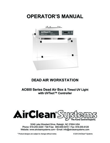
OPERATOR’S MANUALDEAD AIR WORKSTATIONAC600 Series Dead Air Box & Timed UV Lightwith UVTect Controller3248 Lake Woodard Drive, Raleigh, NC 27604 USAPhone: 919-255-3220 Toll Free: 800-849-0472 Fax: 919-255-6120Website: www.aircleansystems.com Email: info@aircleansystems.com* Product designs are subject to change without notice. 2012 AirClean Systems
CONTENTSSECTIONWarrantyDeclaration of ConformitySymbols and DefinitionsCautions and PrecautionsTechnical SpecificationsOverviewInstallation InstructionsController InstructionsProgramming MenusOperating InstructionsAlarm MessagesMaintenance: Bulbs Cleaning14-1616Spare Parts ListOptionsShipping ClaimsContact Information1617-181919FIGURESFigure 1, AC600DBC interiorFigure 2, Lifting the workstation properlyFigure 3, Swell latch locationsFigure 4, Linecord connectionsFigure 5, Control panel layoutFigure 6, Fluorescent bulb replacement2PAGE345678911121313PAGE8910101114
WARRANTYWarranty registration must be completed online.To activate warranty visit:aircleansystems.com/warrantyAirClean Systems is committed to providing our customers with quality equipment and serviceafter the sale. We request that you take a moment to fill out the warranty registration form ataircleansystems.com/warranty so that we may ensure prompt and efficient service in the future.AirClean Systems provides a warranty on all parts and factory workmanship. The warranty includesareas of defective material and workmanship, provided such defect results from normal and properuse of the equipment.The warranty for all AirClean Systems products will expire one year from date of shipment fromAirClean Systems, except for DrySafe and CyanoSafe product lines, which carry a two-yearwarranty from date of shipment.This limited warranty covers parts and labor, but not transportation and insurance charges. In theevent of a warranty claim, contact AirClean Systems or the dealer who sold you the product. Ifthe cause is determined to be a manufacturing fault, the dealer or AirClean Systems will repair orreplace all defective parts to restore the unit to operation. Under no circumstances shall AirClean Systems be liable for indirect, consequential, or special damages of any kind. This statement may bealtered by a specific published amendment. No individual has authorization to alter the provisions ofthis warranty policy or its amendments. Lamps and filters are not covered by this warranty. Damagedue to accidental breakage is also not covered.NOTE: Do not return any materials without authorization from AirClean Systems.Products returned without prior authorization will not be accepted. AirClean Systemsand its dealers are not responsible for shipping damage. The recipient must fileclaims directly with the freight carrier. If authorization has been received to return thisproduct, by accepting this approval, the user assumes all responsibility and liabilityfor biological and chemical decontamination and cleansing. AirClean Systems reservesthe right to refuse delivery of any products which do not appear to have been properlycleaned and/or decontaminated prior to return. Please see additional Shipping Claimson Page 20.IMPORTANT: Complete the warranty registration form at aircleansystems.com/warranty3
DECLARATION OF CONFORMITYWe:AirClean Systems, Inc.of:3248 Lake Woodard DriveRaleigh, North Carolina 27604USAdeclare that:Product Name:Ductless PCR WorkstationModel Numbers:AC632DBC and AC648DBCin accordance with the following Directives:73/23/EEC89/336/EECThe Low Voltage Directive as amended by 93/68/EECEMC Directive as amended by 92/31/EEChas been designed and manufactured to the following specifications:Safety:IEC 61010: 2001 SAFETY REQUIREMENTS FOR ELECTRICAL EQUIPMENTFOR MEASUREMENTEMC:CISPR 11 Electromagnetic Disturbance Characteristics - Limits AndMethods of MeasurementIEC 61000-4-2 Electromagnetic Compatibility, ESDIEC 61000-4-3 Electromagnetic Compatibility, Radiated ImmunityIEC 61000-4-4 Electromagnetic Compatibility, Fast TransientIEC 61000-4-5 Electromagnetic Compatibility, SurgeIEC 61000-4-6 Electromagnetic Compatibility, Conducted ImmunityIEC 61000-4-8 Electromagnetic Compatibility, MMIEC 61000-4-11 Electromagnetic Compatibility, Voltage InterruptionThe CE marking has been affixed on the device according to article 10 of the EMC Directive 89/336/EEC.I hereby declare that the equipment named above has been designed to comply with the relevantsections of the above referenced specifications. The unit complies with the essential requirements of thedirectives.Signed by: Name:Position:M. Kevin McGoughGeneral ManagerRaleigh, North Carolina USA 15- Apr-20044
SYMBOLS THAT MAY APPEAR ON YOUR ENCLOSUREAlerts the user to the presence of dangerous voltages within the product’s enclosure thatmaybe of sufficient magnitude to constitute a risk of electric shock to persons.Alerts the user to the presence of important operating maintenance or service instructions.Alerts the user to the possible presence of ultraviolet light.Alerts the user that two persons are required for safe lifting of the object.The presence of this symbol means that this equipment has been designed, tested andcertified as complying with the applicable Underwriter’s Laboratory (USA) regulations andrecommendations.The presence of this symbol means that this equipment has been designed, tested andcertified as complying with all of the essential requirements applicable to European Union (CE)regulations and recommendations.This symbol alerts the user to the correct replacement fuses for the product.AbbreviationDefinitionPPEPersonal Protective EquipmentOSHAOccupational Safety and Health AdministrationACGIHAmerican Conference of Government Industrial HygienistsTLVThreshold Limit ValueUVUltravioletMSDSMaterial Safety Data Sheet5
CAUTIONS AND PRECAUTIONSNotices in this ManualWARNINGCAUTIONIndicates a potentially hazardous situation, which if not avoided, could result in death orserious injury.Indicates a potentially hazardous situation, which if not avoided, may result in minoror moderate injury. It may also be used to alert against unsafe practices or potentialequipment damage.General CautionsAlways use a properly grounded line cord and receptacle.Always replace fuses with those specified.These instructions must be placed in an easily seen location.DO NOT use this equipment for purposes other than nucleic acid preparation and amplificationof non-biological substances.DO NOT use this system until it has been properly installed.DO NOT operate this unit if the linecord appears damaged or frayed in any way.DO NOT attempt to access non-user serviceable components of system.DO NOT operate this unit if display is blank or hard to read. If display is hard to read, callcustomer service.DO NOT look directly at the UV light.6
TECHNICAL SPECIFICATIONSSPECIFICATIONSPhysical DimensionsOutside DimensionsInside DimensionsWeightElectricalVoltageCurrentPower ConsumptionMains AltitudeHumidityInstallation CategoryPollution DegreeConstructionTop MaterialFront Panel and Sides (3)Base MaterialOptionsCart w/ two 4” locking wheelsAC632DBCAC648DBC32”w x 30”h x 24”d31”w x 18”h x 23”d100 lbs.48”w x 32”h x 24”d47”w x 19”h x 23”d150 lbs.110VAC 60 Hz or 230VAC 50 Hz1.4A / .7A150W 10%110VAC 60 Hz or 230VAC 50 Hz2.8A /1.4A300W 10%3A 250V, Slow Blow 5 X 201 (110V) / 2 (230V)6.3A 250V, Slow Blow 5 X 201 (110V) / 2 (230V)Indoor Use OnlyUp to 2000m80% Max up to 31C DecreasingLinearly to 50% at 40CII2Indoor Use OnlyUp to 2000m80% Max up to 31C DecreasingLinearly to 50% at 40CII2ABSLexan PolycarbonateStructural PolypropyleneABSLexan PolycarbonateStructural Polypropylene32”l x 24”w x 34”h48”l x 24”w x 34”h7
OVERVIEWThe AC600 Series DBC Workstation, with UVTect microprocessor-driven controller provides 254nm short-wave UV light to effectively irradiate contaminating DNA and RNA within minutes. Shortwave UV bulbs (254 nm) have a definable useful life of 1000 hours in your workstation. The UVTect Controller tracks UV bulb hours and alerts the user when to replace the UV bulb. The overlappingsash design prevents operator exposure to shortwave UV energy.WARNINGTHIS WORKSTATION IS NOT DESIGNED FOR USEWITH BIOLOGICAL SAMPLES.How the AC600DBC Workstation works:1. UV light sterilizes pipette tips, tubesand flasks.UV LightFluorescentLightPipetteShelfSlip HatchFigure 1, AC600DBC interior8
INSTALLATION INSTRUCTIONSCAUTIONDO NOT lift the workstation by the head assembly, thesash, or any protruding wires.1) If ordered, assemble the mobile cart. Assembly instructions are included with the cart andalso in the OPTIONS section of this manual. (Page 20)2) Designate the appropriate installation location. Make sure that the desired area is stableenough to hold the workstation and that there is an appropriate AC wall receptacle near theworkstation. Do not place workstations near doors or windows.3) With the help of a co-worker, lift the workstation out of the bottom tray of the box. Make sureto lift from the bottom of the workstation. See figure 2.Figure 2, Lifting the workstation properly4) Place the workstation in the desired location. Once in place, make sure that it is secureand stable.5) Visually inspect your workstation, checking for any damage that may have occurred inshipping. Pay special attention to the sash hinges. If damage has occurred, call AirClean Systems immediately. DO NOT attempt to use workstation.7) Make sure that the swell latches, located on the side lip of the head assembly, are in thelatched (down) position and that the head assembly is secure and properly seated. Seefigure 3. (Page 10)9
Swell LatchSwell LatchAC632DBC modelAC648DBC modelFigure 3, Swell latch locations.8) Ensure that the door switch cable on the right hand side of the head assembly issecure. See figure 4.CAUTIONOnly use approved accessories with the exteriorconnectors.9) Make sure that any exterior linecord connections are secure and seated properly. Theseconnections are located on the back of the workstation. See figure 4.10) Locate the power entry module on the back of the workstation. Insert the female end of thelinecord into the power entry module and the male end into an appropriate electrical outlet.See figure 4.AC632DBC modelPower EntryModuleAC648DBC modelPower EntryModuleLinecordLinecordFigure 4, Linecord Connections.10
CONTROLLER INSTRUCTIONSFigure 5, Control panel layout.QUICK KEYSUV LIGHT (light blue icon) - One touch to enable UV light bulb. When front sash isopened, safety switch automatically turns UV light off to prevent exposure. Front sashmust be closed for UV light to illuminate.LIGHT (yellow icon) - Inactive key for workstation. (Light will automatically turn onwhen front sash is opened and turn off when sash is closed.)TIMER - User definable lab event timer.AUX - Inactive key for workstation.NAVIGATION KEYSMODESELECTSETAllows the operator to move between different program screens.Allows movement within each program screen. The user modifiable portions of thescreen will be blinking.Allows operator to adjust the following user definable settings: Lab event timer UV light timer Time/Date* All other settings are factory pre-set and should not be changed.11
PROGRAMMING MENUSNOTE: The UVTect controller has been pre-programmed by AirClean Systems to allow theunit to be operational immediately. (The fluorescent light, which is preset to run at fullspeed, automatically turn on when sash is opened.) The UV light time is preset to stay on for a15-minute period when the sash is closed and the UV key is depressed. MAIN MENU - Displays the time, date, and status when the main power is on and thecontroller power is off. When controller power is activated the screen will display one ofthe following and may be changed by pressing the “Select” arrow keys: UV Timer - UV light timer, factory set at 15 minutes. Timer - General lab event timer, factory set at 20 minutes.Press “Mode” arrow keys to scroll between the following program screens:TIMER - Allows operator to turn the lab event timer on/off and set a specific amount of time.Pressing the “Timer” quick key on the controller will activate the timer.UV - Allows operator to set operation time of UV light. It is factory preset for 15 minutes.TIME/DATE - Operator can change displayed time and date.ALARM ENABLE - THIS SCREEN IS FACTORY PRESET. DO NOT ALTER THIS SCREEN!Controls audio/visual alarms for workstation.NOTE: You can deactivate the audible alarm, when it sounds, by touching the alarmbutton on the controller. The visual alarm will still work.UV LAMP - Displays hours remaining for UV bulb life.NOTE: Each time the UV bulb is illuminated, a minimum of one hour will be used.Each UV bulb has a life expectancy of 1000 bulb hours. The workstation will alarmbefore the bulb life expires. For complete instructions on replacing the UV bulb, referto the Maintenance Section on Page 17.ADDITIONAL INFORMATION Changes within each program are automatically saved. After programming the above options, use the quick keys to activate/deactivatethe features.12
OPERATING INSTRUCTIONS1) To activate the main power of the workstation, flip the switch above the power inlet. Seefigure 5.2) On the controller, the green light on the POWER quick key should be illuminated. If it is not,press the POWER quick key once to turn on the system. While the system is on, the topline of the controller screen will read “SYS OK” and display the time. The bottom line of thecontroller will read one of the following, and can be changed by pressing the SELECT arrowkeys: Timer - General lab event timer UV Time - UV light timer, factory set at 15 minutesTo change settings, see Controller Instructions on page 11.3) Open the front sash. The fluorescent light should turn on. When sash is closed, thefluorescent light should turn off.4) To begin the sterilization period, close the sash completely and press the UV light quickkey on the controller. The UV light timer will count down from 15 minutes. The UV light willautomatically turn off when the timer reaches zero.Note: The UV light will automatically turn off when the front sash is opened and willactivate when the sash is closed. The UV light timer will continue counting down once thesash is closed.5) Always close the front sash when the workstation is not in use and press the “POWER”button on the controller to turn off the unit. The LCD screen will display the time and date.6) Clean the unit on a scheduled basis. See MAINTENANCE section for instructions. (page 18)ALARM MESSAGESThe alarms that are built into the system are maintenance related. They are designed to tellthe operator about conditions that may affect the operation of the workstation and decrease itsperformance. ALARMUV CHECK - The UV light alarm occurs after 900 use-hours of the UV bulb.(One use-hour an hour of actual use or one on/off cycle of the light.) After 1000 use-hours,the UV bulb may glow blue but the UV radiation may not be effective. Replacement of theUV bulb is required.13
MAINTENANCEBULBSFluorescent Bulb ReplacementThe AC632DBC workstation contains one fluorescent bulb, and the AC648DBCworkstation contains two fluorescent bulbs. They may be replaced as needed with a 15WCool White Bulb.To replace the fluorescent light bulb in the AC632 model:CAUTIONDisconnect the linecord from the power entrymodule prior to proceeding.1. Turn off power at the power entry module. Disconnect linecord from the power entrymodule. See figure 4. (Page 10)2. Completely open the folding front sash by carefully resting it on the head assembly ofthe workstation.3. Using both hands, turn the bulb counter clockwise ¼ turn and remove from thelight socket. See figure 7.4. Install new bulb by sliding into the light socket and turning clockwise ¼ turn until thebulb locks into place.5. Reconnect linecord to power entry module. Turn the power on at the power entry module.See figure 4. (Page 10)AC632DBC modelAC648DBC modelFigure 7, Fluorescent bulb replacement.14
To replace the fluorescent light bulb in the AC648DBC model:CAUTIONDisconnect the linecord from the power entrymodule prior to proceeding.1. Disconnect linecord from the power entry module. Disconnect the door switch cable andlight cables. See figure 4. (Page 10)2. Using both hands, turn the bulb counter clockwise ¼ turn and remove the bulbfrom the socket.3. Install new bulb by sliding into the light socket and turning it clockwise ¼ turn until thebulb locks into place.4. Reconnect the linecord, door switch cable, and light cables.UV Bulb ReplacementEach UV bulb has a life expectancy of 1000 bulb hours. The UVTect Controller will track theremaining UV bulb hours. Each time the UV bulb is illuminated, a minimum of one hour will beused. The alarm will sound when 100 UV bulb hours remain. When the life of the UV bulb hasexpired, the UV light will not work until a new bulb is installed.CAUTIONDisconnect the linecord from the power entrymodule prior to proceeding.To replace the UV light bulb(s) in the AC632DBC or AC648DBC models:1. Turn off power at the power entry module. Disconnect linecord from the power entrymodule. See figure 4. (Page 10)2. Completely open the folding front sash by carefully resting it on the head assembly ofthe workstation.3. Using both hands, turn the bulb counter clockwise ¼ turn and remove from the light socket.4. Take note of the serial number on the sleeve of the new bulb prior to installing. Install newbulb by sliding into the light socket and turning clockwise ¼ turn until the bulb locks5. Reconnect linecord to power entry module. Turn the power on at the power entry module.See figure 4. (Page 10)To enter validation number of new UV bulb:1. Press the “MODE” arrow keys until the UV Lamp screen is displayed. This screen willdisplay the number of remaining useful hours for the UV bulb.2. Press the “SELECT” up arrow key.3. Using the “SET” keys, enter the new UV bulb validation number starting with the first digit.Press the “SELECT” up arrow key to move to the next digit.4. Repeat until the entire validation number is entered.5. Press the “SELECT” up arrow key until the “ ” caret blinks.6. Finish by pressing the “SET” up arrow key once to store the UV bulb validation number.15
CLEANINGExterior: Clean with only a soft, damp cotton cloth or an acrylic cleaner. Do not use paper products to clean unit, as they may scratch the material.Interior: A high level disinfectant or 10% bleach/water solution may be used as needed. Sporicidin isan approved disinfectant for use with AirClean Systems PCR workstations.WARNINGInterior cleaning with an approved disinfectant should becompleted routinely. Residual moisture must be removed orUV radiation may cause chemical burn of the polycarbonate. Ifthis occurs contact AirClean Systems technical support beforecontinued usage of product.SPARE PARTS LISTCATALOG 50215ACAUVBL4DESCRIPTIONElectronics Box (648)Controller Touch PadPower Inlet Fuse, 3.15 A, Slow BlowPower Inlet Fuse, 6.3 A, Slow BlowIEC ConnectorDoor SwitchLight FixturePower Cord¼-20 x 1 PH bolt for fixed sash¼-20 Lock nutSash HingesPolycarbonate Front Sash, CompletePolycarbonate Front Sash, CompletePolycarbonate shellPolycarbonate shellPolypropylene BasePolypropylene BasePolycarbonate Sash Rails15W Cool White Fluorescent LampUV Bulbs, Pack of 4AC632N/A11N/A11214441N/A1N/A1N/A211Product designs are subject to change without notice, contact Customer Service before placing order.16AC64811N/A11141448N/A1N/A1N/A1222
OPTIONSAIRCLEAN SYSTEMS CART ASSEMBLY INSTRUCTIONSModel ACA1011 and ACA1039Your AirClean Systems Cart is shipped with the following components:4 - Cross pieces2 - End pieces8 - Hook & Loop Fasteners (4 Hook, 4 Loop)8 - 2” x ¼” Phillips head bolts(cross piece bolts)8 - 1¼” washers (cross piece washers)4 - CastersASSEMBLY OF CART1. Locate a cart end piece and one cart cross piece. Place one 3/8” washer on to a 2”phillips head bolt.2. Starting with hole one on the cart end piece place washer and bolt through the holeand into the threaded receiver of the cart cross piece. Hand-tighten only until cart iscompletely assembled.3. Repeat steps above for holes 2 and 3.4. For standard setup complete assembly using hole 4. For seated use completeassembly using hole 5.5. Tighten all bolts completely.6. Installation of casters should be per illustration on page 21.MOUNTING OF Enclosure TO ASSEMBLED CART1. Remove the adhesive backing from one hook-side fastener and adhere to the top of the cartend piece, one inch from the front.2. Repeat step one, adhering the fastener one inch from the back.3. Repeat steps one and two for the other cart end piece. There should be strips of hook-sidefasteners on all four corners of the top of the cart (see cart components diagram).4. Attach loop-side fasteners to the hook-side fasteners and peel off the backing so theadhesive is exposed on all four corners.5. Carefully place the enclosure on the assembled cart, lining up the enclosure and cart edges.6. Firmly push down on the edges of the base inside the workstation so the adhesive sticks tothe enclosure base.17
CART COMPONENTSLocation for Hook& Loop Fasteners8 - 1¼” WasherTOPHookHole 1LoopHole 2Hook & Loop Fasteners4 - HookHole 34 - Loop8 - 2” x ¼” Bolt4 - Cart Cross PieceHole 4Hole 5BOTTOM2 - Standard Caster2 - Locking Caster2 - Cart End PieceASSEMBLED CART CONFIGURATIONSStandard Setup18For Seated Use
SHIPPING CLAIMSIf a shipment is received with visible damage, be certain to make a notation on the delivering carrier’sreceipt and have their agent confirm the damage on your receipt. Otherwise, the damage claim maybe refused.If concealed damage or pilferage is discovered, notify the carrier immediately and retain the entireshipment intact for inspection. Interstate Commerce Commission rules require that the claim be filedwith the carrier within 15 days of delivery.NOTE: Do not return any materials without authorization from AirClean Systems.Products returned without prior authorization will not be accepted. AirClean Systemsand its dealers are not responsible for shipping damage. The recipient must fileclaims directly with the freight carrier. If authorization has been received to return thisproduct, by accepting this approval, the user assumes all responsibility and liabilityfor biological and chemical decontamination and cleansing. AirClean Systems reservesthe right to refuse delivery of any products which do not appear to have been properlycleaned and/or decontaminated prior to return.CONTACT INFORMATIONIf you have any questions that are not addressed in this manual, or if you need technical assistance,please contact AirClean Systems at 800-849-0472, between the hours of 8:00 AM and 5:30 PM EST.AirClean Systems mailing address:AirClean Systems3248 Lake Woodard DriveRaleigh, NC 27604Phone: 919-255-3220 Toll Free: 800-849-0472 Fax: 919-255-6120Visit AirClean Systems on the Internet at: http://www.aircleansystems.comEmail AirClean Systems at: info@aircleansystems.comMODEL NO.SERIAL NO. AC632DBCAC632-DBC AC648DBCAC648-DBC19
3248 Lake Woodard Drive, Raleigh, NC 27604Phone: 919-255-3220 Toll Free: 800-849-0472 Fax:919-255-6120Website: www.aircleansystems.com Email: info@aircleansystems.com* Product designs are subject to change without notice. 2012 AirClean Systems
3) With the help of a co-worker, lift the workstation out of the bottom tray of the box. Make sure to lift from the bottom of the workstation. See figure 2. CAUTION DO NOT lift the workstation by the head assembly, the sash, or any protruding wires. 4) Place the workstation in the desired location. Once in place, make sure that it is secure and .