Transcription
Flame detector ( UV/IR Type )RFD-2000X User’s ManualRezontech Co., Ltd
Co.,Ltd.UV/IR Type Flame DetectorRFD-2000XTABLE OF CONTENTS1 Product Overview1.1 Product Introduction1.2 Contents of User Manual1.3 Revision of User Manual1.4 Warranty2 Technical Specifications2.1 Electrical Specifications2.2 Mechanical Specifications2.3 Environmental Specifications3 Installation3.1 Unpacking & Checking3.1.1 Product Compositions3.1.2 Components3.1.3 Necessary tools3.2 Selection of Installation Location3.2.1 Cone of Vision3.2.2 Range of Detection3.2.3 Environment points to be considered when use3.3 Installation and Electrical Wiring3.3.1 Wiring Detector3.3.1.1 Conduit Installation3.3.1.2 Cable Selection for Electrical Wiring3.3.1.3 Conduit or Gland Standard (Connector)3.3.2 Using of bracket during installation3.3.2.1 Bracket Specification3.3.2.2 Installation of detector with bracket to the wall or the ceiling3.3.3 Terminal Wiring3.3.3.1 Relay Signal3.3.3.2 4-20mA (Current Source Wiring Contact)3.3.3.3 RS4853.3.3.4 External Recovery Signal Electrical Wiring3.3.3.5 Signal of Electrical wiring for3.3.4.external remote self-testInstallation/Setting3.3.4.1 Sensitivity setting3.3.4.2 Setting of delay time3.3.4.3 Setting of others function3.3.5.Ground connection3.3.5.1 Internal Ground connection method3.3.5.2 External Ground connection methodDocument No. Manual-2000X Rev.2March 2012- 1 -
Co.,Ltd.UV/IR Type Flame DetectorRFD-2000X4 Operation4.1 Product checklist4.2 Initial Operation of Product4.3 Safety Handling4.4 Product Testing5 Maintenance & Troubleshooting Instructions5.1 Tools of Maintenance and Products Training5.2 Maintenance Procedures5.3 Troubleshooting5.3.1 No LED responds after the power connection.5.3.2 Yellow LED blinking (2Hz)5.3.3 When receiver unable to detect various signal6 Customer Support6.1 Contacts Information7 Appendix7.1 Abbreviation7.2 Choosing of Wiring7.2.1 Reference: Standard Chart for Power Supply Electrical Wiring duringsetting (AWG Standard)7.2.2 Things to be consider when choosing electrical wiring for power supply7.3 Certification & ApprovalsDocument No. Manual-2000X Rev.2March 2012- 2 -
Co.,Ltd.UV/IR Type Flame DetectorRFD-2000X1. Product Overview1.1Product IntroductionModel RFD-2000X from Rezontech Co., Ltd. is UV/IR type flame detector. It activatesalarm signal or fire extinguishing system via fire or flame detection. This function can beused directly with output terminal and through connected control circuits are also available.Various output methods are available for choice:ㆍ Dry contact Relays (Fire, Fault, Warning)ㆍ 4 20mA Current Outputㆍ RS-485 CommunicationRFD-2000X is a product with additional Internal/External recovery feature which enables tobe widely used in difference applications.1.2Contents of User ManualAll the information about detectors and its features are described on this handling manual.its contents consist of 7 different sections as per stated on [Table 1] below .Title1. Product IntroductionContentGeneral introduction, products overview, briefintroduction on each part2. Technical SpecificationElectrical, mechanical and environmental specifications3. InstallationWiring, mode select, proper installation4. OperationOperation mode and user interface display5. Maintenance &Troubleshooting6. Customer Support7. AppendixMaintenance and technical support procedureAbout This product will be customer service willdescribe the informationAbbreviations, authentication, and parts will be describeinformation about products[Table 1] Contents of User ManualDocument No. Manual-2000X Rev.2March 2012- 3 -
Co.,Ltd.1.3UV/IR Type Flame DetectorRFD-2000XRevision of User ManualVersionDate of Revision1.0March, 20102.0March, 2012ContentRegistration of documentpara# 2.2.2 3.2.2, 3.3.2,3.3.4Remarksamendment[Table 2] Revision of User Manual1.4WarrantyRezontech warrants the Models RFD-2000X to be free from defects in workmanship ormaterial under normal use and service within two years from the date of shipment.Rezontech will repair or replace without charge any such equipment found to be defectiveduring the warranty period. Full determination of the nature of, and responsibility for,defective or damaged equipment will be made by Rezontech’ personnel.Defective or damaged equipment must be shipped to Rezontech’ plant or representativefrom which the original shipment was made. In all cases this warranty is limited to thecost of the equipment supplied by Rezontech. The customer will assume all liability forthe misuse of this equipment by its employees or other personnel.All warranties are contingent upon proper use in the application for which the product wasintended and does not cover products which have been modified or repaired withoutRezontech’ approval, or which have been subjected to neglect, accident, improperinstallation or application, or on which the original identification marks have been removedor altered.Except for the express warranty stated above, Rezontech disclaims all warranties withregard to the products sold, including all implied warranties of merchantability and fitnessand the express warranties stated herein are in lieu of all obligations or liabilities on thepart of Rezontech for damages including, but not limited to, consequential damagesarising out of, or in connection with, the performance of the product.Document No. Manual-2000X Rev.2March 2012- 4 -
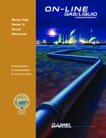
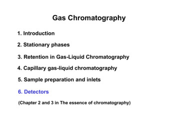
Co.,Ltd.UV/IR Type Flame DetectorRFD-2000X2. Technical Specifications2.1Electrical Specifications[Figure 1] TB1 Terminal address at product cover2.1.1Electricalㆍ Recommended Operating Voltage : 24VDCㆍ Rating Voltage : 17VDC 32VDCㆍ Max Input Voltage : 36VDCㆍ Max Consumption Power : 1.8W (at 17VDC )ㆍ Normal Average Current : approximate 35mA (at 24VDC)ㆍ Max Operating Current : approximate 70mA(at 17VDC, during detection of fire or self-diagnosis test)2.1.2Relay Outputㆍ 2A 28VDC, 4A 125VAC, 2A 250VACㆍ Dry Contactㆍ A(Normally Open) or B(Normally closed)2.1.34 20mA Current Outputㆍ Non-isolation output, Common 24V- IN(-Power)ㆍ Max. Terminating Resistance : 500Ωㆍ 0mA ( 0.5mA) : Connection Faultㆍ 2mA ( 0.5mA) : Self-diagnosis test Faultㆍ 4mA ( 0.5mA) : Normalㆍ 8mA ( 0.5mA) : IR Detectionㆍ 12mA ( 0.5mA) : UV Detectionㆍ 16mA ( 0.5mA) : Warning (UV and IR Detection, fire occurs during delay time)ㆍ 20mA ( 0.5mA) : Fire DetectionDocument No. Manual-2000X Rev.2March 2012- 5 -
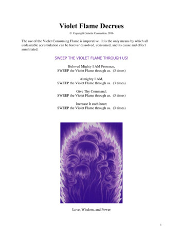
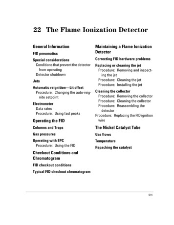
Co.,Ltd.2.1.4UV/IR Type Flame DetectorRFD-2000XRS485 Communicationㆍ Non-isolation output (2 wiring)ㆍ Communication Speed : 9600bps2.1.5LED Indicatorㆍ Two LED's(Yellow, Red) indicator- Yellow LED : Provides indication of Normal or Fault state- Red LED : Provides indication of Warning or Alarm stateㆍ Product reset process : Yellow & Red LED intersection blinking repeatedly (3 sec)ㆍ Normal : Yellow LED blinking (0.5Hz)ㆍ Power supply or Self-diagnosis test fault : Yellow LED blinking (2Hz)ㆍ Warning : Yellow LED blinking (0.5Hz) and Red LED blinking (2Hz)ㆍ Alarm : Yellow LED blinking (0.5Hz) and Red LED lightingㆍ Warning at BIT Fault : Yellow LED blinking (2Hz) and Red LED blinking (2Hz)ㆍ Alarm at BIT Fault : Yellow LED blinking (2Hz) and Red LED lightingGroundingYellow LEDGreen LED[Figure 2] Product Image LED position indicatorDocument No. Manual-2000X Rev.2March 2012- 6 -
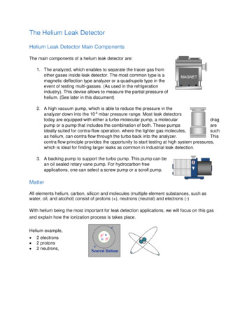
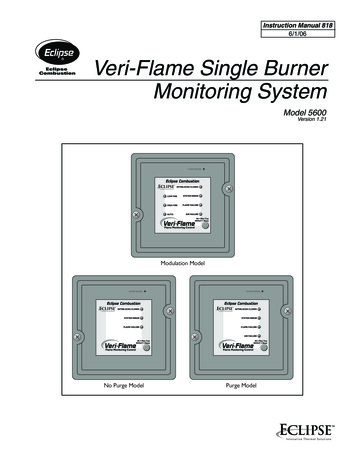
Co.,Ltd.2.2UV/IR Type Flame DetectorRFD-2000XMechanical Specifications[Figure 3] Front, inch[mm][Figure 4] Side, inch[mm][Figure 5] Combination of Detector and Bracket, inch[mm]ㆍ Enclosure (Material) : 316 Stainless Steelㆍ Weight : Body - approximate 2.4 , Overall - approximate 3.4 ㆍ Dimension(Body) : W5.3[134.00] H4.6[117.00] D4.7[120.00] (inch[mm])ㆍ Dimension(Overall) : W5.3[134.00] H6.41[163.00] D14.39[365.68] (inch[mm])ㆍ Color : Metalㆍ Electrical connection (External) : 1/2 inch NPT-14, M20 X 1.5ㆍ Wire gauge (Power supply & Signal) : AWG #12 (3.31 ) #24 (0.205 )ㆍ Hazardous Area Approvals : Class I Div.1 Groups B,C and DClass II Div.1 Groups E,F and GClass IIIDocument No. Manual-2000X Rev.2March 2012- 7 -
Co.,Ltd.UV/IR Type Flame DetectorRFD-2000Xㆍ Explosion proof : ATEX Ex d IIB H2 T6 (75 )ㆍ Water and Dust Tight : IP67, NEMA Type 4X2.3Environmental Specificationsㆍ Operating Temperature : -40 75 ㆍ Storage Temperature : -50 80 ㆍ Humidity : Relative humidity 95%Document No. Manual-2000X Rev.2March 2012- 8 -
Co.,Ltd.UV/IR Type Flame DetectorRFD-2000X3. Installation3.1Unpacking & CheckingPlease check the external condition of detector when unpacking the product carefully. Ifthere is any damage on the products, please contact the local distributor immediately orany trouble in used products, please send it to A/S center with fee applied.3.1.1Product Compositionsㆍ RFD-2000X 1EAㆍ BK-2(Bracket) 1EAㆍ Spare Bolt 1setㆍ Tools3.1.2Components3.1.2.1 Fundamental componentsComponentstandardQ'ty (pcs)DescriptionHexagon wrench BoltM6 102Join the Detector and Bracket4Join the Detector4Install the BracketM6 35Hexagon wrench Bolt(OEM)Metric button screw ( )M5 30[Table 3] Fundamental components3.1.2.2 Spare componentsComponentStandardQ'ty (pcs)DescriptionHexagon wrench BoltM6 102Join the Detector and Bracket4Join the Detector4Install the BracketHexagon wrench BoltMetric button screw ( )M6 35(OEM)M5 30[Table 4] Space Components3.1.3 Necessary toolsTool nameStandardQ'ty (pcs)DescriptionHexagon wrench driverMetric,5M1Join the detector, bracketScrew driver 1Install the Bracket[Table 5] Necessary toolsDocument No. Manual-2000X Rev.2March 2012- 9 -
Co.,Ltd.3.2UV/IR Type Flame DetectorRFD-2000XSelection of Installation LocationMinimum information will be provided below for the location selection of installation.Please refer the information according to the purpose of your use.3.2.1Cone of Vision3.2.1.1 Fuelㆍ N-Heptane3.2.1.2 Cone of Visionㆍ Horizontal / Vertical : 90 ( 45 up, down, left, right at 50% of detection range )[Figure 6] Cone of Vision3.2.2Range of DetectionThe detection distance for the alarm level is 50ft(18m) from the standard fire.The detector has two response levels.ㆍWarningㆍAlarm3.2.2.1 Detection Range of FuelsType Of FuelMaximum Distance (ft / m)N-Heptane98.5 / 30[Table 6] Range of Fuels DetectionDocument No. Manual-2000X Rev.2March 2012- 10 -
Co.,Ltd.UV/IR Type Flame DetectorRFD-2000X3.2.2.2 Detection Range of False AlarmThe detector is immune to a variety of false alarm sources. Representative samples ofdetector's response from false alarm sources are listed below.Radiation SourceImmunity Distance ft(m)Indirect or reflected sunlightNo fire alarmIncandescent lamp 100WNo fire alarmFluorescent light 40WNo fire alarmResistive electric heater 1500WNo fire alarmBlue, Green dome light XXXWNo fire alarmHot plate (200 )No fire alarmHalogen lamp 500W (Glass)No fire alarmHalogen lamp 1000W (Quartz lamp)12 (4)Grinding metal3.3 (1)Arc welding (5mm, 200A)15 (4.6)[Table 7] Types of False Alarm source and Its Relationship between Flame Detection3.2.3Environment points to be considered when useㆍ Installation places and availability of fuels (Family of Hydrocarbon and relatedflame detection)ㆍ install product according to its Installation space and it areas of dangerous(internal/external etc)ㆍ Select place of installation according to detection range and field of viewㆍ Temperature range [Min/Max] of operation/installationㆍ Select the place to avoid the area with obstructed object for the appropriate installationㆍ Select the place to avoid the area with false alarm statuses affect to the fire detection※ The above points of considerations are based on the basic environmental standard andthey are vary different between countries in terms of environment, usage, users etc.Document No. Manual-2000X Rev.2March 2012- 11 -
Co.,Ltd.3.33.3.1UV/IR Type Flame DetectorRFD-2000XInstallation and Electrical WiringWiring the Detector3.3.1.1 Conduit installationㆍ Use 1/2 inch NPT-14 or M20X1.5 conduit connection or suitable explosion-proof glandto assemble the cable and conduit to the detector.ㆍ When using conduit connection for Division installation, conduit seals must be installedwithin 18 inches (450mm) from the enclosure.ㆍ When using conduit connection for ATEX installation, conduit seals must be placed atenclosure.ㆍ Install the conduit including drain holes place downward to avoid water condensation inthe detector.3.3.1.2 Cable Selection for Electrical Wiringㆍ All cables to the detector should be well shielded for EMC.ㆍ Wire gauge for detectors power supply wires.AWG No.Diameter( )Cross section( 1.31151.451.65141.632.08131.832.63122.053.31[Table 8] American Wire Gauge Standard3.3.1.3 Conduit or Gland Standard (Connector)ㆍ Cable Conduit Standard : 1/2 inch NPT-14, M20 X 1.5ㆍ Water and Dust : IP67, NEMA Type 4XDocument No. Manual-2000X Rev.2March 2012- 12 -
Co.,Ltd.3.3.2UV/IR Type Flame DetectorRFD-2000XUsing of bracket during installation3.3.2.1 Bracket Specificationㆍ Angle adjustment : Horizontal 180 , Vertical 180 , scale indications 15 eachWhen you arrange the angle, M4 Set Screw and M10-25 Hexagon Wrench Bolthas to be released first and tighten again with 24 (N・m) Torgue for HexagonWrench Bolt and 1.5 (N・m) Ttorgue for Set Screw.ㆍ Enclosure Material : 316 Stainless Steelㆍ Weight : Body - approximate 2.4 , Overall - approximate 3.4 ㆍ Dimension(Body) : W5.3[134.00] H4.6[117.00] D4.7[120.00] (inch[mm])ㆍ Dimension(Overall) : W5.3[134.00] H6.41[163.00] D14.39[365.68] (inch[mm])ㆍ Color : Metalㆍ Wall mounted size : 6Φ 4 (5mm bolt)[Figure 7] Bracket BK-023.3.2.2 Installation of detector with bracket to the wall or the ceilingㆍ Necessary tool : Hexagon Wrench Driver, Screw Driverㆍ component : Metric M6-10 2 pcs, Metric M5-30 4pcsㆍ Flame detector's body and cover has to be combined with M6-35 Hexagon WrenchDriver at 5(N・m) Torque.ㆍ Flame detector and bracket is connected with Hexagon Wrench Bolt at 5(N・m) Torque.Document No. Manual-2000X Rev.2March 2012- 13 -
Co.,Ltd.UV/IR Type Flame DetectorRFD-2000Xㆍ Mount the bracket with M5-30 4pcs bolts. Refer to Figure 17ㆍ Detector can be installed on the wall or the ceiling with bracket. Refer to Figure 18, 19[Figure 8] 4 Holes on bracketfor mounting detector[Figure 10]Ceiling mount[Figure 9] Wall mountDocument No. Manual-2000X Rev.2March 2012- 14 -
Co.,Ltd.3.3.3UV/IR Type Flame DetectorRFD-2000XTerminal WiringThis is the reference for the user on how all the connection of the electrical wiring areconnected to each system or product as per stated below.3.3.3.1 Relay Signal- Fire RelayThe following signal occurs when fire is detectedㆍ The operational status of fire relay according to detector's condition.Relay statusTB1Fire RelayNormal(De-Energized)Fire(Energized)5,20ALM N.CClosedOpen6,19ALM N.OOpenClosed7,18ALM COMCommonCommon- 2A@28VDC, 4A@125VAC, 2A@250VAC[Table 9] Fire Relay operatedㆍ Interlink wiring of Power Supply, Fire Relay, Fault Relay[Figure 11] Terminal wiring diagram schematic at fire alarm relayDocument No. Manual-2000X Rev.2March 2012- 15 -
Co.,Ltd.UV/IR Type Flame DetectorRFD-2000X- Fault RelayThis signal shows up when product is not working properly or the fire signal is notfunctional.※ Before power supply is on, FLT N.O is connected because Fault Relay is not in errorstatus.ㆍ Fault Relay OperatedType of FaultDescriptionsPower SupplyThe error status of external and internal power supplySelf TestingThe error status of basic function (fire detection)[Table 10] Fault Relay Operatedㆍ Fault Relay operated according to detector's conditionRelay StatusTB1Fault RelayNormal(Energized)Fault(De-Energized)3,22FLT N.COpenClosed3,22FLT N.OClosedOpen4,21FLT COMCommonCommon- 2A@28VDC, 4A@125VAC, 2A@250VAC- Change Fault Relay's FLT N.O/N.C mode accordingly by switching the jumper.- FLT N.O is available by default[Table 11] Fault Relay Operating StatusDocument No. Manual-2000X Rev.2March 2012- 16 -
Co.,Ltd.UV/IR Type Flame DetectorRFD-2000Xㆍ Power supply Fire, Relay and Fault Relay wires interlink(indication of Jumper setting location)[Figure 12] Terminal wiring diagram schematic at fault relay (Internal)[Figure 13] Terminal wiring diagram schematic at fault relay (External)Document No. Manual-2000X Rev.2March 2012- 17 -
Co.,Ltd.UV/IR Type Flame DetectorRFD-2000Xㆍ Loop connection with several detectorsThis is Loop type connection method which can generate alarm and fault signal. Butwith this connection, detection performance is blocked when one flame detector is in faultcondition. So this method is only avaliable with specific receiver which can check faultsignal frequently and automatically.[Figure 14] Terminal wiring diagram schematic for LOOP connectionDocument No. Manual-2000X Rev.2March 2012- 18 -
Co.,Ltd.UV/IR Type Flame DetectorRFD-2000X- Warning RelayThis signal shows when fire is detected at primary stage before the real fire is confirmed.This signal only occurs within delay time.ㆍ Warning Relay operated according to detector's conditionRelay statusTB1Warning RelayNormal(De-Energized)Warning(Energized)17WARN N.CClosedOpen16WARN N.OOpenClosed15WARN COMCommonCommon2A@28VDC, 4A@125VAC, 2A@250VAC[Table 12] Warning Relay Operating Statusㆍ Interlink electrical wiring of Power supply Fire Relay, Fault Relay, and Warning Relay[Figure 15 ] Terminal wiring diagram schematic at fault and warning relayDocument No. Manual-2000X Rev.2March 2012- 19 -
Co.,Ltd.UV/IR Type Flame DetectorRFD-2000X3.3.3.2 4 20mA (Current Source)This signal shows when various recorded information of current output is transmittedthrough electrical wiring. It is varied according to the product status.ㆍ Non-isolation output, Common 24V- IN (-Power)ㆍ Max. Terminating Resistance : 500Ω- Types of Signalㆍ 0mA ( 0.5mA) : Connection Faultㆍ 2mA ( 0.5mA) : Self-Diagnosis test Faultㆍ 4mA ( 0.5mA) : Normalㆍ 8mA ( 0.5mA) : IR Detection onlyㆍ 12mA ( 0.5mA) : UV Detection onlyㆍ 16mA ( 0.5mA) : UV and IR Detection (Warning)ㆍ 20mA ( 0.5mA) : Fire Detection- Signal of electrical wiring (3 Lines-Sourcing)[Figure 16] Terminal wiring diagram schematic at 4 20mA outputDocument No. Manual-2000X Rev.2March 2012- 20 -
Co.,Ltd.UV/IR Type Flame DetectorRFD-2000X3.3.3.3 RS485This signal (RS485) does not inform product status only but also supports changing andcontrolling in variable setting value. And this function can be used in synch withinterlinking remote control or other systems.Signal terminal number (TB1)TB111Signal nameCOMM-12COMM 13COMM 14COMM[Table 13] TB1 communication terminal number- Communication Specificationㆍ Non-isolation communicationㆍ Full-duplex, half-duplexㆍ 9600bps basic settingㆍ 1:N support (Client)ㆍ support protocol : manufacturer protocol- Signal of Electrical Wiring[Figure 17] Terminal wiring diagram schematic at RS-485 communicationDocument No. Manual-2000X Rev.2March 2012- 21 -
Co.,Ltd.UV/IR Type Flame DetectorRFD-2000X3.3.3.4 External Recovery SignalIt is used when the detector needs to recover from its default status after any firedetection, etc. Hence, it is similar to reset product via power on/off.Signal terminal number (TB1)TB18Signal nameRESET RLY[Table 14] TB1 External recovery signal terminal number- Signal Specificationㆍ Operating Signal : same level of signal with 24V- INㆍ Operating delayed time : 5 secondsㆍ Operating continuous time : after cancelling operating signal reset time※ After using the function above, signal must be opened first for the proper operation.- Signal of electrical wiring[Figure 18] External recovery signal electrical wiring diagramDocument No. Manual-2000X Rev.2March 2012- 22 -
Co.,Ltd.UV/IR Type Flame DetectorRFD-2000X3.3.3.5 External Self-Diagnosis TestWithin the various parts of fire detector, sensor is the most basic receiving part nearliestfrom 'fire signal' with transmission function. This function is enable to inspect from thereceiving part to fire recognition circuit.Signal terminal number (TB1)TB1No.9Signal nameTEST RLYChange JP1's jumper to TEST RLY[Table 15] TB1 Terminal number for external self-test signal- Signal Specificationㆍ Operating signal : same level of signal with 24V- INㆍ Operating delayed time : 5 secondsㆍ Operating continuous time : operating delayed time 10 secs. (approx. 20 secs.)ㆍ The result of signalResult signalNormalFault- Fault Relay output (De-Energized)Normal output for all signals- 2mA ( 0.5mA) : self-test error signal- Yellow LED blinking (2Hz)- Response of communication self-test faulty signal[Table 16] External self-test signal table- Signal of electrical wiring[Figure 19] External self-test signal External self-testDocument No. Manual-2000X Rev.2March 2012- 23 -
Co.,Ltd.3.3.4UV/IR Type Flame DetectorRFD-2000XSetting of Product3.3.4.1 Sensitivity settingSensitivity setting can be adjusted by user according to the various environmentalconditions. Due to the difference in law or regulation from various countries, this functionmay not be applicable to all. So we have no responsibility for the troubles related withsensitivity setting over the approved range.ㆍ FM Approval response range : No.3 of SW1, OFF("0")ㆍ FM Approval does not allow : No.3 of SW1 ON("1")- Setting method of sensitivityDo not set the switch, while power is applied. The switch adjustment with powerconnection will not be recognized by the detector.ㆍ The sensitivity of No. 3 at SW1, OFF("0")SW1Switch settingSensitivityRange of 98.5(30)0XX-98.5(30)ft(m)[Table 17] Sensitivity range of N-Heptaneㆍ The sensitivity of No.3 at SW1, ON("1")SW1Switch settingSensitivityRange of 165(20)101Middle-282(25)111High98.5(30m)- Reference Source of fire standard is 70 70 of N-Heptane- FM Approval does not allow[Table 18] Sensitivity range of N-HeptaneDocument No. Manual-2000X Rev.2March 2012- 24 -
Co.,Ltd.UV/IR Type Flame DetectorRFD-2000X3.3.4.2 Setting of Delay TimeThe flame detectors are equipped with Alarm delay option, which provides programmabletime delays by settings. The Alarm signal will be activated if the fire still exists afterprogrammed delay time. But the fire disappears within programmed delay time, thedetector will return to its standby state again.The Alarm delay option affects the output relays and the 0-20mA. The LEDs and outputsindicate warning levels during the delay time only if the fire condition exists.SW1Switch settingDelay 25[Table 19] Switch setting for delay time※ When setting of delay time to 5, an average response time is about 12 second for 1X1feet heptane pan flame at 98.5 feet (30 m) from FM approval results.3.3.4.3 Setting of Others Function- Setting of Alarm Signal LatchThis is the recovery signal when source of fire is disappear or setting is out of range.This supports two kinds of setting. First, user can recovery fire detector through powering"OFF" and "ON" manually or using "RESET RLY" terminal. Second, it recoveriesautomatically in 5 seconds if status of fire detection signal is cancelled.SW1Switch SettingFunctionNo.70Automatic Recovery "OFF"1Alarm Latch "ON"[Table 20] Switch setting for recovering signal of fire detectionDocument No. Manual-2000X Rev.2March 2012- 25 -
Co.,Ltd.UV/IR Type Flame DetectorRFD-2000X- Setting of Self Checking FunctionAfter the appropriate installation, the detector performs self diagnostic test by itself fromthe internal sensor to circuit repeatedly.SW1Switch SettingFunctionNo.80Self testing function "OFF"1Self testing function "ON"- Period of self testing : Every 12 hours[Table 21] Switch setting for self-diagnosis test3.3.5Ground ConnectionFor proper operation of the detector, the RFD-2000X must be grounded through a wire tothe chassis.Failure to establish a ground connection can lead to greater susceptibility of thedetector to electric surges, electromagnetic interference, and ultimately, damage to theinstrument.3.3.5.1 Internal Grounding MethodConnect Hole in the internal "Board01" and PCB to enclosure connection bolt withelectrical line.3.3.5.2 External Grounding MethodGround with connection line located in right side of enclosure.Document No. Manual-2000X Rev.2March 2012- 26 -
Co.,Ltd.UV/IR Type Flame DetectorRFD-2000X4. OperationThe contents of this page are about "Operation". As much as ‘product selection’ or‘Installation’, the operation is also very important. Though another parts of operation"Maintenance and Troubleshooting" will be discussed separately in another chapter.ㆍ Product Inspectionㆍ Initial Operation of Productㆍ Safety Handlingㆍ Product Testing4.1Product InspectionFor the appropriated operation after the installation, the essential information for inspectionwill be described below.4.1.1Inspection of Installation conditionsIf there are any inferior or bad installation, Reinstallation can be recommended. Thisminimum inspection can affect to the duration and performance of the products.ㆍ Product Fixing Conditionsㆍ Inspection of Product Assembly Conditions (Internal Wiring and Joins)ㆍ Installation height and angle of different products are vary accordingly.ㆍ The conditions of product after combination with others product.(Explosive-proof and water proof, other electrical conditions )4.2 Initial Operation of ProductThe product operation will be explained below under the assumption that all the requiredwiring, such as main power supply(24VDC) or signals is connected properly.Document No. Manual-2000X Rev.2March 2012- 27 -
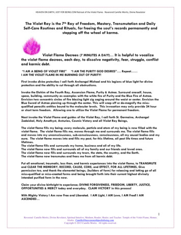
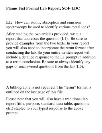
Co.,Ltd.UV/IR Type Flame DetectorRFD-2000XInitial OperationStatusOperate or Output StatusBefore inserting- Fault Relay signal Open (Normally Open : De-Energized)power supply- All LED OFF- Fault Relay signal Closed (Normally Closed : lt- After 7 seconds of self-diagonosis test, LED intersect for3seconds (Yellow Red Yellow.) blinking- All output, "normal" signal output (Normally Closed : Energized)- YELLOW LED blinking 0.5Hz- Closed of Fault Relay signal (Normally Closed : De-Energized)- LED "Fault" signal output- Current "'Fault" signal- Communication "Fault" signal[Table 22] Initial Operation of Product4.3Safety HandlingThere are a few points to be taken note when the products are used with the powerconnection.ㆍ Please refer to the diagrams and specifications on the user manualㆍ Do not open the product while the power supply is 'On', especially in dangerousarea, further cautions are needed more.ㆍ Disassembly and assembly of the internal electrical parts of the product are notallowed to anyone, except the manufacturer. Unauthorized action within the internalelectrical parts will expire the warranty.ㆍ When trying to detached the product from its installed place (including full system),advanced checking for interrelation with related system must be placed to avoidmalfunction.4.44.4.1Product TestingProduct Testing by using : TL205TL 205 generates specific UV/IR radiations which can be detected by Rezontech Flamedetector series as fire. It has an individual built in internal power supply hence, it can bemoved and used easily. It can be continuously working up to 30 minutes. For moredetails kindly refer to the user manual.※ If everything is fine without any problem during the testing period by using the testlamp, the flame detector will generate actual fire alarm signal which can activate allrelated fire fight system, so appropriate preparation and inspection must be placed beforethe test with TestLamp.Document No. Manual-2000X Rev.2March 2012- 28 -
Co.,Ltd.UV/IR Type Flame DetectorRFD-2000X[Figure 20] TL205 TEST LAMPㆍ Testing Sequences with TL2051. Please wait for 10seconds after the power is supplied. Check, Yellow LED blinking.2. Face and 'Turn On' the TL 205 in front of the flame detector.3. The recommended distance between test lamp and product shall be within 5Mwhen point no. 2 above is performed.4. If "Red LED" is lighting on the flame detector, fire is detected generally.5. If the product is set to be recovering manually, the recovery will be start byturning OFF/ON of the power supply6. If "Red LED" does not light on during the test stage 2,3, please adjust the distanceand re-test again. If the same problem persists and even after the TestLamp is ingood conditions after the inspection (as per below stated), please contact themanufacturer or A/S center. The flame detector might have defects.Power supplystatus checkingScope of Inspection- TestLamp's No.1 or No.2 lamp is not functioning, it means theTestLamp is defected.- If TestLamp's lamp No.1 is blinking and the radiation intensity isweak, or if it's No.2 lamp is not functioning, please re-charge theTestLamp.[Table 23] Lighting Status of Test lampProduct Operation Status Vary According to Testing ConditionsStatusOperate or Output StatusBefore inserting- Fault Relay signal Open (Normally Open : De-Energized)power supplyInsertingAfterpower- All LED OFF- Fault Relay signal Closed (Normally Closed : Energized)insertingpowersupplysupplyNormalFire- After 7 seconds of self-diagonosis test, LED intersect for3seconds (Yellow Red Yellow.) blinking- All output, "normal" signal output (Normally Closed : Energized)- YELLOW LED blinking 0.5Hz- All output "Fire" signal[Table 24] Product Operation Status Vary According to Testing ConditionsDocument No. Manual-2000X Rev.2March 2012- 29 -
Co.,Ltd.UV/IR Type Flame DetectorRFD-2000X5. Maintenance and TroubleshootingThis chapter deals with preventive maintenance, describes possible faults in detectoroperation and indicates corrective measures. Ignoring these instructions may causeproblems with the detector and may invalidate the warranty. Whenever a unit requiresservice, please contact rezontech or its authorized distributor for assistance.5.1Tools of Maintenance and Products TrainingBasic tools are necessary and the person in-charge shall received products training inorder to maintain the detector. The setting issues and its related issue, regulations shallbe well
Co.,Ltd. UV/IR Type Flame Detector RFD-2000X Document No. Manual-2000X Rev.2 March 2012 - 1 - TABLE OF CONTENTS 1 Product Overview 1.1 Product Introduction 1.2 Contents of User Manual 1.3 Revision of User Manual 1.4 Warranty 2 Technical Specifications 2.1 Electrical Specifications 2.2 Mechanical Specifications 2.3 Environmental Specifications