Transcription
Basic Electronics & TheoryLesson 5From: Emergency Management Ontario5.1 Metric PrefixesMetric prefixes you'll need to know .1 Giga (G) 1 billion 1,000,000,0001 Mega (M) 1 million 1,000,0001 kilo (k) 1 thousand 1,0001 centi (c) 1 one-hundredth 0.011 milli (m) 1 one-thousandth 0.0011 micro (u) 1 one-millionth 0.0000011 pico (p) 1 one-trillionth 0.000000000001. and a few you might want to know .1 Tera (T) 1trillion 1,000,000,000,0001 hecto (h) ten 101 deci (d) 1 tenth 0.11 nano (n) 1 one-billionth 0.0000000011
Basic Electronics & TheoryLesson 5From: Emergency Management Ontario5.1 Metric PrefixesThe prefix enables us to reduce the amount of zeros that are used in writing outlarge numbers.For example. instead of saying that the frequency of my signal is 1,000,000 Hz(Hertz or cycles per second) I can say that it is 1,000 kilohertz (kHz) or even 1Megahertz (MHz). The prefix enables us to write the number in a shorter form. Thisespecially becomes useful when we need to measure VERY large or VERY smallnumbers.2
Basic Electronics & TheoryLesson 5From: Emergency Management Ontario5.1 Metric Prefixes Mega- (one million; 1,000,000)Just to make certain that this stuff makes sense, lets go back and look at largefrequencies again.1,000 Hz 1 kHz"One thousand Hertz equals one kilohertz"1,000,000 Hz 1 Mhz"One million Hertz equal one megahertz"So how many kilohertz are in one megahertz? 1000 kHz 1 MHz"One thousand kilohertz equals one megahertz"So if your radio was tuned to 7125 kHz, how would you express that samefrequency in megahertz?1000 kHz 1 MHz 7125 kHz 7.125 MHz(It takes 1000 kilohertz to equal 1 megahertz, so 7125 kilohertz would equal 7.125megahertz.)3
Basic Electronics & TheoryLesson 5From: Emergency Management Ontario5.1 Metric Prefixes Mega- (one million; 1,000,000)Lets do another frequency problem. This time, your dial reads 3525 kHz. What is thesame frequency when expressed in Hertz? This should be simple.1 kHz 1000 Hz 3525 kHz 3,525,000 Hz(Notice that since we have to add three zeros to go from 1 kHz to 1000 Hz, we mustalso do the same to go from 3525 kHz to 3,525,000 Hz.)Now, let's work another frequency problem, except we're going to do it backwards.Your displays shows a frequency of 3.525 MHz. What is that same frequency inkilohertz?1 MHz 1000 kHz 3.525 MHz 3525 kHz(See how the 1 became 1000? To go from megahertz to kilohertz, you multiply by1000. Try multiplying 3.525 MHz by 1000 to get your frequency in kilohertz.)4
Basic Electronics & TheoryLesson 5From: Emergency Management Ontario5.1 Metric Prefixes Giga- (one billion; 1,000,000,000)Now we're going to deal with an even larger frequency. Remember, kilo equals onethousand, and mega equals one million. What equals one billion? There is a prefixfor one billion - Giga. One billion Hertz is one gigahertz (GHz). What if you weretransmitting on 1.265 GHz? What would your frequency be in megahertz? Howmany millions equals one billion? 1 billion is 1000 millions, so 1 gigahertz (GHz) is1000 megahertz (MHz).1 GHz 1000 MHz 1.265 GHz 1265 MHzAs you begin to see how these metric prefixes relate to each other, it will becomeeasier to express these large and small numbers commonly used in radio andelectronics.5
Basic Electronics & TheoryLesson 5From: Emergency Management Ontario5.1 Metric Prefixes Milli- (one one-thousandth; 0.001)If you were to take an ammeter (a meter that measures current) marked in amperesand measure a 3,000 milliampere current, what would your ammeter read?First, what does milli- mean? Milli might be familiar to those of you who were alreadyfamiliar with the ever popular centimeter.The millimeter is the next smallest measurement. There are 100 centimeters in 1meter. there are also 1000 millimeters in 1 meter.So milli must mean 1 one-thousandth.If your circuit has 3,000 milliamps (mA), how many amps (A) is that?1,000 mA 1 A 3,000 mA 3 A6
Basic Electronics & TheoryLesson 5From: Emergency Management Ontario5.1 Metric PrefixesNow lets say, on a different circuit, you were using a voltmeter marked in volts (V),and you were measuring a voltage of 3,500 millivolts (mV). How many volts wouldyour meter read?1,000 mV 1 V 3,500 mV 3.5 VHow about one of those new pocket sized, micro handheld radio you're itching tobuy once you get your license? One manufacturer says that their radio puts out 500milliwatts (mW) , while the other manufacturer's radio will put out 250 milliwatts(mW). How many watts (W) do these radios really put out?1000 mW 1 W 500 mW 0.5 W1000 mW 1 W 250 mW 0.25 W7
Basic Electronics & TheoryLesson 5From: Emergency Management Ontario5.1 Metric Prefixes Pico- (one one-trillionth; 0.000000000001)Capacitors are devices that usually have very small values. A one farad capacitor isseldom ever used in commercial electronics (however I understand that they aresometimes used when a lot of stored up energy is needed for an instant).Usually, your run of the mill capacitor will have a value of 1 thousandth of a farad to1 trillionth of a farad.This is the other end of the scale compared with kilo, mega, and giga. Now we'lllearn about micro and pico.If you had a capacitor which had a value of 500,000 microfarads, how many faradswould that be?Since it takes one million microfarads to equal one farad.1,000,000 uF 1 F 500,000 uF 0.5 F8
Basic Electronics & TheoryLesson 5From: Emergency Management Ontario5.1 Metric Prefixes Pico- (one one-trillionth; 0.000000000001)What if we had a capacitor with a value of 1,000,000 picofarads? Pico is a very, verysmall number, so to have 1 million pico farads is saying that the value is just verysmall instead of very, very small. One picofarad is one trillionth of a farad. Onepicofarad is also one millionth of a microfarad. So it takes one million picofarads(pF) to equal one microfarad (uF).1,000,000 pF 1 uFBy the way, just so you get a grasp of just how small a picofarad really is,remember, it would take one trillion (i.e. one million-million) picofarads (pF) to equalone farad (F), or.1,000,000,000,000 pF 1 F9
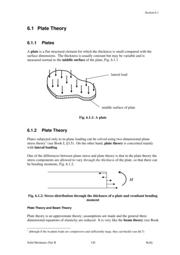
Basic Electronics & TheoryLesson 5From: Emergency Management Ontario5.2 Concepts of Current, Voltage, Conductor, Insulator, Resistance CurrentWater flowing through a hose is a goodway to imagine electricity Water is likeElectrons in a wire (flowing electronsare called Current).Pressure is the force pushing waterthrough a hose – Voltage is the forcepushing electrons through a wireFriction against the holes walls slowsthe flow of water – Resistance is animpediment that slows the flow ofelectrons10
Basic Electronics & TheoryLesson 5From: Emergency Management Ontario There are 2 types of current– The form is determined by the directions the currentflows through a conductor Direct Current (DC)– Flows in only one direction from negative towardpositive pole of source Alternating Current (AC)– Flows back and forth because the poles of the sourcealternate between positive and negative11
Basic Electronics & TheoryLesson 5From: Emergency Management Ontario5.2 Concepts of Current, Voltage, Conductor, Insulator, ResistanceConductors and InsulatorsThere are some materials that electricity flows through easily. These materials arecalled conductors. Most conductors are metals.Four good electrical conductors are gold, silver, aluminum and copper.Insulators are materials that do not let electricity flow through them.Four good insulators are glass, air, plastic, and porcelain.12
Basic Electronics & TheoryLesson 5From: Emergency Management Ontario5.3 Concepts of Energy & Power, Open & Short CircuitsThe Open CircuitThe open circuit is a very basic circuit that we should all bevery familiar with. It is the circuit in which no current flowsbecause there is an open in the circuit that does not allowcurrent to flow. A good example is a light switch. When thelight is turned off, the switch creates an opening in thecircuit, and current can no longer flow.You probably figured that since there are "open circuits" that there are probably also "closedcircuits". Well, a closed circuit is when the switch is closed and current is allowed to flowthrough the circuit.A fuse is a device that is used to create an open circuit when too much current is flowing.13
Basic Electronics & TheoryLesson 5From: Emergency Management Ontario5.3 Concepts of Energy & Power, Open & Short CircuitsThe Short CircuitA short circuit can be caused by incoming powerwires (wires that are normally insulated and keptseparate) coming in contact with each other. Since acircuit usually has resistance, and the power wiresthat "short out" have very little resistance, the currentwill tend to flow through the path of leastresistance. the short. Less resistance at the sameamount of voltage will result in more current to flow.Therefore a short circuit will have too much current flowing through it. What's the best way to stopa short circuit from doing damage (because it is drawing too much power from the source)? Byusing a fuse. Fuses are designed to work up to a certain amount of current (e.g. 1 amp, 15 amps,.). When that maximum current is exceeded, then the wire within the fuse burns up from the heatof the current flow. With the fuse burnt up, there is now an "open circuit" and no more currentflows.14
Basic Electronics & TheoryLesson 5From: Emergency Management Ontario5.3 Concepts of Energy & Power, Open & Short CircuitsPowerEvery circuit uses a certain amount of power. Powerdescribes how fast electrical energy is used. A goodexample is the light bulbs used in each circuit of yourhome. When you turn on a light bulb, light (and heat) areproduced. This is because of the current flowing througha resistor built into the bulb. The resistance turns theelectrical power into primarily heat, and secondarily light(assuming an incandescent bulb).Each light bulb is rated at a certain power rating. This is how much power the bulb will use in a normal110 Volt house circuit. Three of the most popular power values for inside light bulbs are 60, 75, and100 Watts (Power is measured in Watts). Which of these light bulbs uses the most power? The 100Watt bulb uses the most power.15
Basic Electronics & TheoryLesson 5From: Emergency Management Ontario 5.4 Ohm’s Law E electromotive force (a.k.a. Voltage)I intensity (French term for Current)R resistance Voltage: E I x R (Volts)Current: I E / R (Amps)Resistance: R E / I (Ohms)16
Basic Electronics & TheoryLesson 5From: Emergency Management Ontario5.4 Ohm’s LawCalculating Voltage and Current and ResistanceCurrent?There is a very easy way to determine how much current will flow through a circuitwhen the voltage and resistance is known. This relationship is expressed in a simpleequation (don't let the word scare you. this is going to be easy as "pie".Let's start with the "pie".This circle will help you to know how to figure out the answer to these electricalproblems. The three letters stand for.E electromotive force (a.k.a. Voltage)I intensity (French term for Current)R resistance17
Basic Electronics & TheoryLesson 5From: Emergency Management Ontario5.4 Ohm’s LawCalculating Voltage and Current and ResistanceCurrent?Lets say you have 200Volts hooked up to a circuit with 100 Ohms of resistance.How much current would flow?Since our "unknown" value in this problem is the current, then we put our finger overthe "I". What you see is "E over R". This means you take the Voltage and divide it bythe Resistance. This is 200 Volts divided by 100 Ohms. The result is 2 Amps.E electromotive force (a.k.a. Voltage)I intensity (French term for Current)R resistance18
Basic Electronics & TheoryLesson 5From: Emergency Management Ontario5.4 Ohm’s LawCalculating Voltage and Current and ResistanceVoltage?What if we wanted to find out the voltage in a circuit when we know the current andresistance? Go back to the "pie" and cover up the E. You're now left with I times R.How much voltage would you need in a circuit with 50 ohms and 2 amps? E IxR.E 2x50. E 100 Volts.E electromotive force (a.k.a. Voltage)I intensity (French term for Current)R resistance19
Basic Electronics & TheoryLesson 5From: Emergency Management Ontario5.4 Ohm’s LawCalculating Voltage and Current and ResistanceResistance?Finally, if you had a circuit with 90 Volts and 3 amps, and you needed to find theresistance, you could cover up the R. the result is E over I (Volts divided byCurrent). R E/I. R 90/3. R 30 Ohms. This circuit would have 30 Ohms ofresistance if it was hooked up to 90 Volts and 3 amps flowed through the circuit.Ohm's LawThis relationship between voltage, current, and resistance is known as Ohm's Law.This is in honour of the man who discovered this direct relationship (his last namewas Ohm). The relationship described in Ohm's Law is used when working withalmost any electronic circuit.20
Basic Electronics & TheoryLesson 5From: Emergency Management Ontario!"&!'(## % % )# %Voltage: E I x R (Volts)Current: I E / R (Amps)Resistance: R E / I (Ohms)
Basic Electronics & TheoryLesson 5From: Emergency Management Ontario* #&! ('#% ) #%Voltage: E I x R (Volts)Current: I E / R (Amps)Resistance: R E / I (Ohms)
Basic Electronics & TheoryLesson 5From: Emergency Management Ontario,&!# #(' %#) - %Voltage: E I x R (Volts)Current: I E / R (Amps)Resistance: R E / I (Ohms)
Basic Electronics & TheoryLesson 5From: Emergency Management Ontario&.-/Voltage: E I x R (Volts)Current: I E / R (Amps)Resistance: R E / I (Ohms)0'1*2/.3566414/.4*0-/3
Basic Electronics & TheoryLesson 5From: Emergency Management OntarioPower calculations– The unit used to describe electricalpower is the Watt.– The formula: Power (P) equals voltage(E) multiplied by current (I).P IxE25
Basic Electronics & TheoryLesson 5From: Emergency Management Ontario Power calculations (cont)– How much power is represented by a voltage of 13.8 voltsDC and a current of 10 amperes.P I x E P 10 x 13.8 138 watts– How much power is being used in a circuit when thevoltage is 120 volts DC and the current is 2.5 amperes.P I x E P 2.5 x 120 300 watts26
Basic Electronics & TheoryLesson 5From: Emergency Management OntarioPower calculations (cont)– You can you determine how many watts are being drawn[consumed] by your transceiver when you are transmittingby measuring the DC voltage at the transceiver andmultiplying by the current drawn when you transmit.– How many amperes is flowing in a circuit when the appliedvoltage is 120 volts DC and the load is 1200 watts. I P/E I 1200/120 10 amperes.27
Basic Electronics & TheoryLesson 5From: Emergency Management Ontario7,/7) 96#)526) :7)566#)526) ;.# 7) 66#)526) :# 7) 5266#)526)567) -#-8Power: P I x E (Watts)Current: I P / E (Amps)Voltage: E P/ I (Volts)E Electromotive Force aka VoltsI Intensity aka Current
Basic Electronics & TheoryLesson 5From: Emergency Management Ontario5.5 Series & Parallel ResistorsSeries circuitsA series circuit is a circuit in which resistors are arranged in a chain, so the currenthas only one path to take. The current is the same through each resistor. The totalresistance of the circuit is found by simply adding up the resistance values of theindividual resistors: equivalent resistance of resistors in series : R R1 R2 R3 .29
Basic Electronics & TheoryLesson 5From: Emergency Management Ontario5.5 Series & Parallel ResistorsSeries circuitsA series circuit is shown in the diagram above. The current flows through eachresistor in turn. If the values of the three resistors are:With a 10 V battery, by V I R the total current in the circuit is:I V / R 10 / 20 0.5 A. The current through each resistor would be 0.5 A.30
Basic Electronics & TheoryLesson 5From: Emergency Management Ontario5.5 Series & Parallel ResistorsSeries circuitsR R1 R2 R3 .R1 100 ohmsR2 150 ohmsR3 370 ohmsRT ? ohms31
Basic Electronics & TheoryLesson 5From: Emergency Management Ontario5.5 Series & Parallel ResistorsSeries circuitsR R1 R2 R3 .R1 100 ohmsR2 150 ohmsR3 370 ohmsRT 620 ohms32
Basic Electronics & TheoryLesson 5From: Emergency Management Ontario5.5 Series & Parallel ResistorsParallel circuitsA parallel circuit is a circuit in which the resistors are arranged with their headsconnected together, and their tails connected together. The current in a parallelcircuit breaks up, with some flowing along each parallel branch and re-combiningwhen the branches meet again. The voltage across each resistor in parallel is thesame.The total resistance of a set of resistors in parallel is found by adding up thereciprocals of the resistance values, and then taking the reciprocal of the total:equivalent resistance of resistors in parallel: 1 / R 1 / R1 1 / R2 1 / R3 .33
Basic Electronics & TheoryLesson 5From: Emergency Management Ontario5.5 Series & Parallel ResistorsParallel circuitsA parallel circuit is shown in the diagram above. In this case the current supplied by thebattery splits up, and the amount going through each resistor depends on theresistance. If the values of the three resistors are:With a 10 V battery, by V I R the total current in the circuit is: I V / R 10 / 2 5 A.The individual currents can also be found using I V / R. The voltage across eachresistor is 10 V, so:I1 10 / 8 1.25 AI2 10 / 8 1.25 AI3 10 / 4 2.5 ANote that the currents add together to 5A, the total current.34
Basic Electronics & TheoryLesson 5From: Emergency Management Ontario5.5 Series & Parallel ResistorsParallel circuits1 / R 1 / R1 1 / R2 1 / R3 .R1 100 ohmsR2 100 ohmsR3 100 ohmsRT ? Ohms35
Basic Electronics & TheoryLesson 5From: Emergency Management Ontario5.5 Series & Parallel ResistorsParallel circuits1 / R 1 / R1 1 / R2 1 / R3 .R1 100 ohmsR2 100 ohmsR3 100 ohmsRT ? Ohms1/100 1/100 1/100 .01 01 .01 .031/.03 33.33 ohms36
Basic Electronics & TheoryLesson 5From: Emergency Management Ontario5.5 Series & Parallel ResistorsA parallel resistor short-cutIf the resistors in parallel are identical, it can be very easy to work out the equivalent resistance.In this case the equivalent resistance of N identical resistors is the resistance of one resistordivided by N, the number of resistors. So, two 40-ohm resistors in parallel are equivalent to one20-ohm resistor; five 50-ohm resistors in parallel are equivalent to one 10-ohm resistor, etc.When calculating the equivalent resistance of a set of parallel resistors, people often forget to flipthe 1/R upside down, putting 1/5 of an ohm instead of 5 ohms, for instance. Here's a way tocheck your answer. If you have two or more resistors in parallel, look for the one with thesmallest resistance. The equivalent resistance will always be between the smallest resistancedivided by the number of resistors, and the smallest resistance. Here's an example.You have three resistors in parallel, with values 6 ohms, 9 ohms, and 18 ohms. The smallestresistance is 6 ohms, so the equivalent resistance must be between 2 ohms and 6 ohms (2 6/3, where 3 is the number of resistors).Doing the calculation gives 1/6 1/12 1/18 6/18. Flipping this upside down gives 18/6 3ohms, which is certainly between 2 and 6.37
Basic Electronics & TheoryLesson 5From: Emergency Management Ontario5.5 Series & Parallel ResistorsCircuits with series and parallel componentsMany circuits have a combination of series and parallel resistors. Generally, the total resistance in acircuit like this is found by reducing the different series and parallel combinations step-by step to end upwith a single equivalent resistance for the circuit. This allows the current to be determined easily. Thecurrent flowing through each resistor can then be found by undoing the reduction process.General rules for doing the reduction process include:Two (or more) resistors with their heads directly connected together and their tails directly connectedtogether are in parallel, and they can be reduced to one resistor using the equivalent resistanceequation for resistors in parallel.Two resistors connected together so that the tail of one is connected to the head of the next, with noother path for the current to take along the line connecting them, are in series and can be reduced toone equivalent resistor.Finally, remember that for resistors in series, the current is the same for each resistor, and forresistors in parallel, the voltage is the same for each one38
Basic Electronics & TheoryLesson 5From: Emergency Management Ontario5.7 AC, Sinewave, Frequency, Frequency UnitsWhat is frequency?The number of cycles per unit of time is called the frequency. For convenience, frequency ismost often measured in cycles per second (cps) or the interchangeable Hertz (Hz) (60 cps 60 Hz), 1000 Hz is often referred to as 1 kHz (kilohertz) or simply '1k' in studio parlance.The range of human hearing in the young is approximately 20 Hz to 20 kHz—the higher numbertends to decrease with age (as do many other things). It may be quite normal for a 60-year-old tohear a maximum of 16,000 Hz.We call signals in the range of 20 Hz to 20,000 Hz audio frequencies because the human earcan sense sounds in this range39
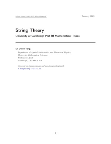
The Relationship of Frequency and WavelengthLesson 5From: Emergency Management OntarioThe distance a radio wave travels inone cycle is called wavelength.V One Cycle0VV-timeOne Wavelength
Basic Electronics & TheoryLesson 5From: Emergency Management OntarioNames of frequency ranges, types of waves- Voice frequencies are Sound waves in the range between 300 and 3000Hertz.- Electromagnetic waves that oscillate more than 20,000 times per second asthey travel through space are generally referred to as Radio waves.41
Basic Electronics & TheoryLesson 5From: Emergency Management OntarioRelationship between frequency and wavelength- Frequency describes number of times AC flows back and forth per second- Wavelength is distance a radio wave travels during one complete cycle- The wavelength gets shorter as the frequency increases.- Wavelength in meters equals 300 divided by frequency in megahertz.- A radio wave travels through space at the speed of light.42
Basic Electronics & TheoryLesson 5From: Emergency Management OntarioIdentification of bandsThe property of a radio wave often used to identify the different bands amateurradio operators use is the physical length of the wave.The frequency range of the 2-meter band in Canada is 144 to 148 MHz.The frequency range of the 6-meter band in Canada is 50 to 54 MHz.The frequency range of the 70-centimeter band in Canada is 420 to 450 MHz.43
Basic Electronics & TheoryLesson 5From: Emergency Management Ontario5.8 DecibelsThe decibel is used rather than arithmetic ratios or percentages because when certaintypes of circuits, such as amplifiers and attenuators, are connected in series, expressionsof power level in decibels may be arithmetically added and subtracted.In radio electronics and telecommunications, the decibel is used to describe the ratiobetween two measurements of electrical powerDecibels are used to account for the gains and losses of a signal from a transmitter to areceiver through some medium (free space, wave guides, coax, fiber optics, etc.)44
Basic Electronics & TheoryLesson 5From: Emergency Management Ontario5.8 Decibels-A two-time increase in power resultsin a change of 3dB higher-You can decrease your transmitter’spower by 3dB by dividing theoriginal power by 2-You can increase your transmitter’spower by 6dB by multiplying theoriginal power by 445
Basic Electronics & TheoryLesson 5From: Emergency Management Ontario5.8 DecibelsIf a signal-strength report is “10dB over S9” ,if the transmitter power is reduced from1500 watts to 150 watts, the report shouldnow be S9If a signal-strength report is “20dB over S9”,if the transmitter power is reduced from1500 watts to 150 watts the report shouldnow be S9 plus 10dBThe power output from a transmitter increases from 1 watt to 2 watts. This is a dB increase of 3.3The power output from a transmitter increases form 5 watts to 50 watts by a linear amplifier. Thepower gain would be 10 dB.46
The InductorLesson 5From: Emergency Management Ontario5.9 Inductance There are two fundamental principlesof electromagnetics:1. Moving electrons create a magnetic field.2. Moving or changing magnetic fieldscause electrons to move. An inductor is a coil of wire throughwhich electrons move, and energy isstored in the resulting magnetic field.47
The InductorLesson 5From: Emergency Management Ontario Like capacitors,inductors temporarilystore energy. Unlike capacitors:– Inductors store energyin a magnetic field, notan electric field.– When the source ofelectrons is removed,the magnetic fieldcollapses immediately.48
The InductorLesson 5From: Emergency Management Ontario Inductors are simplycoils of wire.– Can be air wound(just air in the middleof the coil)– Can be woundaround a permeablematerial (material thatconcentratesmagnetic fields)– Can be woundaround a circularform (toroid)49
The InductorLesson 5From: Emergency Management Ontario Inductance is measured in Henry(s). A Henry is a measure of the intensity ofthe magnetic field that is produced. Typical inductor values used in electronicsare in the range of millihenry (1/1000Henry) and microhenry (1/1,000,000Henry)50
The InductorLesson 5From: Emergency Management Ontario The amount ofinductance isinfluenced by anumber of factors:– Number of coilturns.– Diameter of coil.– Spacing betweenturns.– Size of the wireused.– Type of materialinside the coil.51
Inductor Performance With DC CurrentsLesson 5From: Emergency Management Ontario When a DC current is applied to an inductor, theincreasing magnetic field opposes the currentflow and the current flow is at a minimum. Finally, the magnetic field is at its maximum andthe current flows to maintain the field. As soon as the current source is removed, themagnetic field begins to collapse and creates arush of current in the other direction, sometimesat very high voltage.52
Inductor Performance With AC CurrentsLesson 5From: Emergency Management Ontario When AC current is applied to an inductor,during the first half of the cycle, the magneticfield builds as if it were a DC current. During the next half of the cycle, the current isreversed and the magnetic field first has todecrease the reverse polarity in step with thechanging current. These forces can work against each otherresulting in a lower current flow.53
The InductorLesson 5From: Emergency Management Ontario Because the magneticfield surrounding aninductor can cut acrossanother inductor inclose proximity, thechanging magnetic fieldin one can causecurrent to flow in theother the basis oftransformers54
Basic Electronics & TheoryLesson 5From: Emergency Management Ontario5.9 Capacitance55
The CapacitorLesson 5From: Emergency Management Ontario56
The Capacitor - DefinedLesson 5From: Emergency Management Ontario A device that storesenergy in electric field. Two conductive platesseparated by a nonconductive material. Electrons accumulate onone plate forcingelectrons away from theother plate leaving a netpositive charge. Think of a capacitor asvery small, temporarystorage battery.57
The Capacitor Physical ConstructionLesson 5From: Emergency Management Ontario Capacitors are ratedby:– Amount of chargethat can be held.– The voltage handlingcapabilities.– Insulating materialbetween plates.58
The Capacitor - Ability to Hold a ChargeLesson 5From: Emergency Management Ontario Ability to hold a chargedepends on:– Conductive platesurface area.– Space between plates.– Material betweenplates.59
Charging a CapacitorLesson 5From: Emergency Management Ontario60
The Capacitor Behavior in DCLesson 5From: Emergency Management Ontario When connected to a DC source, thecapacitor charges and holds the charge aslong as the DC voltage is applied. The capacitor essentially blocks DCcurrent from passing through.61
The Capacitor Behavior in ACLesson 5From: Emergency Management Ontario When AC voltage is applied, during one half ofthe cycle the capacitor accepts a charge in onedirection. During the next half of the cycle, the capacitor isdischarged then recharged in the reversedirection. During the next half cycle the pattern reverses. It acts as if AC current passes through acapacitor62
The Capacitor - Capacitance ValueLesson 5From: Emergency Management Ontario The unit of capacitance is the farad.– A single farad is a huge amount ofcapacitance.– Most electronic devices use capacitors thatare a very tiny fraction of a farad. Common capacitance ranges are:MicroNanoPicoµnp10-610-910-1263
The Capacitor - Capacitance ValueLesson 5From: Emergency Management Ontario Capacitor identificationdepends on the capacitortype. Could be color bands, dots,or numbers. Wise to keep capacitorsorganized and identified toprevent a lot of work tryingto re-identify the values.64
Capacitors in CircuitsLesson 5From: Emergency Management Ontario Three physicalfactors affectcapacitance values.– Plate spacing– Plate surfacearea– Dielectric material In series, plates arefar apart makingcapacitance less Charged platesfar apart-C1C2CE C1 C265
Capacitors in CircuitsLesson 5From: Emergency Management Ontario In parallel, thesurface area of theplates add up to begreater. This makes the totalcapacitance higher. -CE C1 C266
Basic Electronics & TheoryLesson 5From: Emergency Management Ontario5.11 Magnetics & TransformersThe transformer is essentially just two (or more) inductors, sharing a common magnetic path.Any two inductors placed reasonably close to each other will work as a transform
Basic Electronics & Theory Lesson 5 From: Emergency Management Ontario The Open Circuit The open circuit is a very basic circuit that we should all be very familiar with. It is the circuit in which no current flows because there is an open in the circuit that does not allow current to flow. A good example is a light switch. When the