Transcription
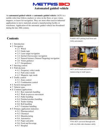
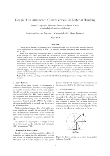
Design of an Automated Guided Vehicle for Material HandlingMaria Margarida Malveiro Bento das Dores Cheiramaria.cheira@tecnico.ulisboa.ptInstituto Superior Técnico, Universidade de Lisboa, PortugalJuly 2019AbstractThis project is focused on the design of an automated guided vehicle (AGV) for material handling,to be implemented at a workshop at TAP. The material handling is currently done manually with theaid of carts.Based on a preliminary design done prior to this work and the current activity at the workshop,a first concept for a AGV that would tow the carts was drafted. Following this, an analysis of thecurrent carts is done, and a mechanism is developed in order to allow the carts to distribute materialautonomously, as well as adaptations are suggested in order to allow the AGV to attach to the carts.The loads to which the AGV and the cart are subjected are then analysed and calculated by makingassumptions about the dimensions of the AGV and then iterating on them. These allow for thecalculation of the torque required for the AGV to pull the cart, which then allows for the dimensioningof the motor. It is also verified whether the AGV has enough traction to be able to pull the cartwithout slipping. Finally, a structural analysis is performed through a computational simulation topredict whether or not the structure of the AGV can withstand the loads previously calculated withoutyielding or disassembling.Keywords: Material handling, Automated Guided Vehicle, Rolling resistance, Design, Finite elementanalysis1. IntroductionWhen talking about the tasks of intralogistics inindustrial environments, material handling appearsas one the most important, as it heavily impactsthe efficiency of the production process and its potential profitability [1]. The classical method usedby companies was manual material handling, but,nowadays, the increasing trend has been the use ofAutomated Guided Vehicles (AGV). An AGV, asthe name might imply, is a vehicle that doesn’t relyon a human driver.While replacing a human with a robot might havesome drawbacks, namely the decreased flexibilityand the high initial investment, it has been shownthat AGVs reduce labour costs, improve safety conditions, and contribute to increased productivity[2].The purpose of this project is to design an AGVto be introduced at the hydraulic and pneumatic(HP) workshop at TAP.forces a vehicle will usually have to overcome arethe ones described in the following subsections.2.1. Rolling ResistanceRolling resistance (Frr ) results from the deformation of a wheel against the ground. Because thematerial of the wheel isn’t perfectly elastic, as thewheel turns there will be energy losses. Translatingthis to forces, it means that the force distributionin the contact area will not be even [3], and the resulting normal reaction will be misaligned with thecentre of the wheel, as can be seen in Figure 1.2. Theoretical BackgroundIn order to begin modelling an electric vehicle, it’simportant to understand the relationship betweenthe motion the vehicle is required to generate andthe forces that it will be subjected to. The typicalFigure 1: Forces acting on a wheel being pulled(adapted from [3])1
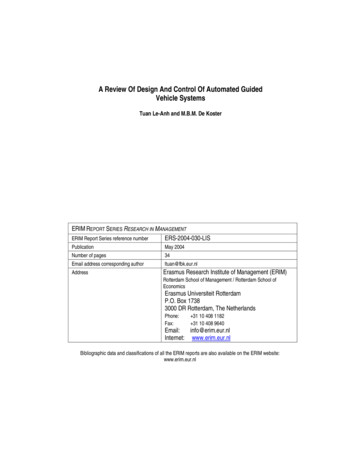
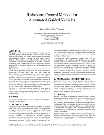
Applying the dynamic equations of motion onegets:XXFx mwheel a F FrrM0 Iα Frr r Rb Frr I(1)a µrr R (2)r2where mwheel is the mass of the wheel, a is the acceleration, r is the radius of the wheel, b is the horizontal distance between R and the centre of the wheel,P is the vertical load on the wheel including weight,R is the normal reaction, F is the force pulling the Figure 2: Free body diagram of a motorized wheel.wheel, I is the moment of inertia of the wheel, α aris the angular acceleration of the wheel, and µrr rbApplying the dynamic equations of motion reis the rolling friction coefficient.sults:2.2. Aerodynamic DragDrag is the force that a fluid will exert on a XFx mwheel a Fte Fr Fr Fte mwheel amoving body that is opposite to its relative motion.(6)Aerodynamic drag (Fad ) is the term used when thesurrounding fluid is air, and it can be expressed byXequation (3),aa(7)M0 I T Fte r T Fte r Irr1(3) where F is the load being pulled, and T is theFad ρair v 2 CD Ar2torque.where ρair is the air density, v is the relative speedbetween fluid and body, CD is the drag coefficient, 3. Project Framework3.1. Workspace and Current Activityand A is the characteristic area.The workshop where the AGV will be introduced2.3. Force of Gravity on an Inclined Planeis divided into several groups, each dedicated to aWhen a vehicle is moving on a plane with inclidifferent category of part or type of repair. Due tonation ψ, its weight (W ) is going to have a comconstraints regarding the layout of the workshop,ponent that is normal to the ground and anotherthis work will be focused on only four main groups,that is parallel. Only the component parallel to thetwo on each side of a 5 meter wide corridor.ground will oppose the movement, and can be deEach day, parts are delivered at the recepfined as:tion/expedition (RE) area in need of repair or maintenance. There, workers separate the parts intoFslope W sinψ(4) trays according to which group they are meant tobe delivered to. A worker will then deliver the trays2.4. Tractive Effort and relation with Torquewith the aid of a cart, as seen in Figure 3.The force that will propel the vehicle forwardIn each group there are two separate but simiis typically called the tractive effort (Fte ) [4], andlar stations containing shelves: a reception station,must be able to overcome all the forces that werewhere the worker places the trays with the unredescribed above, as well as external forces thatpaired parts, and an expedition station, where themay be acting on the vehicle in the direction ofworker takes the trays with the repaired parts from.motion(Fext,x ). As such, the tractive effort can beThe trays with the repaired parts are then takendefined by equation 5.back to the RE area.3.2. Requirements and RestrictionsThe AGV must be able to follow a defined path,know when to stop, and be able to recognize obstaThis force is the result of the static friction that cles and avoid bumping into them. It should alsooccurs between the wheel and the ground as a result be able to transport, pick up, and deliver materialfrom a torque being applied to the wheel by a motor. throughout the different work groups. It should beThe free body diagram of a motorized wheel pulling able to do all of this autonomously. It should bea load can be seen in Figure 2.designed so that it can be built using TechnoLeanFte mvehicle a Frr Fad Fslope XFext,x (5)2
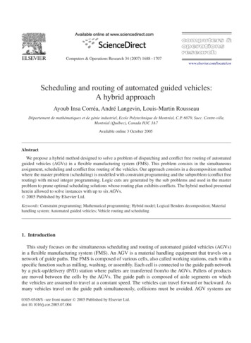
tion, meaning it would have a steerable drive wheelat the front and two supporting wheels at the back.The motorized wheel chosen for this application wasthe one by the Italian company C.F.R.For this type of vehicle, the use of rechargeable batteries was more convenient. It was decidedthat lithium-ion batteries would be used, since theydon’t have memory effect, the AGV can take advantage of idle time to charge, and not just when thebattery is fully drained.Table 1 displays the estimated final dimensionsof the AGV, as well as the weight.Figure 3: Cart with traysTable 1: Vehicle total dimensionsLength (mm)1875Width (mm)600Height (mm)294Weight (kg)172.05material from the company Quimilock, since thistype of material is readily available at TAP, andpreferably it should be made the most use out ofwhat already exists at the workshop. Also, the introduction of the AGV in the workshop should notinterfere (or the interference should be minimized)with the current mode of operation in the workshop. In terms of battery life, the AGV should beable to work a full shift, but should also have anautonomous charging scheme, and should be ableto take any opportunity to charge the battery.While a budget was not defined for the designedof the AGV, an effort should be made in keepingthe design simple and affordable.One of the main downsides of the preliminary design was the fact the the vehicle was very long. Thecarts that the AGV is supposed to carry are 920 mmlong, making the AGV almost a full meter longerthan its cargo. However, the preliminary designwas completely restrained by the dimensions of itscomponents, namely the lifting table, which was thebiggest component in the AGV. The decision wasthus made to change the type of AGV from a liftingunderride to a towing underride.3.3. Previous WorkThe introduction of an AGV on this particularworkshop at TAP is a project that has already seensome study. Prior to this work, Enrique SerranoMartı́nez [5] wrote a thesis where a preliminary design for the AGV’s system was made. In it, heconcluded the best type of AGV for this workshopwould be an underride AGV, with a lifting tableto lift the carts, that would follow a magnetic tapearound a path like the one seen in Figure 4.4. Material Distribution System4.1. Current Carts and CargoA schematic of the carts being currently used canbe seen in Figure 5, and a picture has been shownpreviously in Figure 3.Figure 5: Cart measurements in mmFigure 4: Single loop path with a single unidirecThe carts were built using only TechnoLean mational lane [5]terial, and consist of a combination of tubes connected by joints, all made of steel. They are supThe AGV would also have a tricycle configura- ported by four swivel castors connected to corner3
plates. The carts have two levels of shelves, withtwo shelves each. Each shelf can fit one 600x400 mmtray or combinations of smaller trays. The shelvesof the carts are composed of inclined roller tracksthat are limited laterally by descend guides. Thisinclination is of about is of about 3 and is achievedthrough the use of connectors with different heights.These connectors don’t allow the trays to slide offthe shelf.The maximum total weight of the cart plus cargowas estimated to be of approximately 108 kg.The aforementioned expedition and receptionstations have a structure similar to the carts, in thesense that they also have inclined shelves composedof roller tracks, where the shelves from the receptionstation are inclined away from the corridor, so thatthe trays slide in the direction of the work area, andthe expedition station’s shelves are inclined towardsthe corridor. Their placement in the workshop andrelatively to the path of the AGV can be seen inFigure 4, where A, C, E, and G are reception stations, and B, D, F, and H expedition stations. Thepath of the AGV will thus follow along the stationsfrom A to H, and it can be seen the stations will beto the right of the AGV as it passes by them.Figure 7: Tray delivery.pany item was found, which can be seen in Figures8 and 9.Simply explained, this mechanism consists of anumber of stoppers that prevent the tray from sliding off the inclined shelf. The stoppers can rotatearound an axis and are connected to a bar that has aprotruding roller. When the cart approaches the receiving shelf, the roller will come into contact witha ramp, forcing the stoppers to rotate and allowing the tray to slide freely. The stoppers are thenbrought back to their original position by a spring.4.2. Distribution SystemIn order for the automatic distribution to bemade possible, the trays need to be able to slide offthe shelves and onto the reception stations. Thiscan be achieved easily through a change in the connectors that secure the roller tracks.The cart should thus approach the reception station, moving parallel to it, and stop in front of it,so that the shelves of the cart align with the shelvesof the station. The trays should then slide from theside of the cart to the reception station’s shelves, ascan be seen schematically represented in Figures 6Figure 8: Schematics of item mechanism – closedand 7.setting [6]Figure 6: Cart approachingFigure 9: Schematics of item mechanism – opensetting [6]Now, a solution to control the sliding of the trayswas necessary. After some research, one by the com-An attempt was made to recreate this mechanism4
using TechnoLean material. The result, which willhenceforth be referred to as lock, can be seen inFigure 10.4.2.1Potential Conflicts and Resolution SuggestionsThe last solution suggested implies that the vertical arm of the lock should have four different heightsettings for the roller, one for each group. However,for two shelves at the same level, if the rollers wereplaced on the same setting, those shelves would beactivated more than once, which could lead to atray being delivered to the wrong place.One possible solution would be to add a verticaloffset to misalign the levels of the rollers for samelevel locks, as shown in Figure 12.Figure 10: Lock – open settingThis mechanism uses four rotating connectors,and two parts forming a ’T’ joint. As for the roller(not represented in the figures), one possible optionwould be to use a wheel that is used for the rollertracks.Figure 12: Vertical misalignment (adapted from [6])Because this lock is completely mechanic, it wasnecessary to ensure that each tray would only bereleased at the right time, i.e., that each of thecart’s shelves would only be triggered to open bythe correct receiving shelf, and no other. The mostversatile solution achieved would be to place rampsat different heights in each station and make therollers adjustable in height, so that every shelf couldpotentially serve every station. For example, thiswould cover both the possibility of there being atray to deliver to each station or all trays to onestation alone, just by adjusting the height of therollers, as seen in Figure 11 (for the sake of clarity,the schematics from item were made use of for thepicturing of this solution).This could also be achieved with a horizontal offset, in which the roller levels would still be alignedvertically, but on the locks from the cart’s rearshelves, the rollers’ notches would be more protruding than the aft shelves, and their corresponding activating ramps should be receded, so that they onlyactivate the locks of the rear shelves. A schematiccan be seen in Figures 14 and 13.Figure 13: Schematic view from above. The reception shelves are represented in green, the ramps ingrey, the rollers in blue, and the offset in yellow.Figure 11: Adjustable rollers (adapted from [6])Figure 14: Horizontal misalignment. The yellowSince this solution would allow for the possibil- shaded areas represent the rollers and ramps thatity of all shelves carrying trays to one single group, have an offset, and the arrow represents the directhen the receiving shelves should be made compat- tion of motion of the cartible with the cart, having the same two levels withtwo shelves each.In Figure 14, the vertical rectangles on the left5
represent the two locks and the four different levUnfortunately, due to lack of time, it was notels for the rollers, and the numbers represent each possible to further develop and concretize this soluof the groups. On the right are represented the tion, but it remained worth to mention, as it couldgroups’ reception stations, where the diagonal lines be relevant for future developments.represent the activating ramps.4.4. CouplingIt was determined earlier that the AGV would4.3. Expedition SystemBesides delivering trays, the AGV is also ex- transport the carts by means of a towing device. Apected to aid in retrieving trays containing repaired similar project [7] accomplished this by means of atowing pin, which was activated with the help of aparts.linear actuator.As was explained before, both the reception andSince the carts are supported by swivel castors,expedition stations will be to the right of the AGV,to avoid the cart and the AGV to rotate relative toand it was also mentioned that what differentiateseach other during curves, potentially causing collithem is the direction to which their shelves are insions between the AGV’s and the cart’s structures,clined. The cart, however, will have all the shelvesit was concluded that the use of two pins would beinclined the same way, so for it to be able to receivebetter than just one.trays from the expedition stations, the cart wouldFigure 16 portrays the suggested design of thehave to be turned around. Because this can’t becoupling structure.done during a route, the reached solution requiresthe distribution of trays and the collection of traysto be done in separate routes.In the routes where the AGV retrieves the repaired parts, the cart should thus be attached tothe AGV in a backwards position, with the shelvesdescending to the left. The mechanism that allowsthe sliding of the trays from the stations’ shelves tothe cart would be the same as described before, using a combination of locks activated by ramps, but,in this case, the locks would be attached to the staFigure 16: Coupling structure (sectioned view)tions’ shelves whereas the activating ramps wouldbe on the cart.As can be seen, the structure is symmetrical, soSince there is no way of knowing a priori howmany trays there are in each group ready to be col- that the AGV can attach to the cart in both direclected, then the best way to avoid any conflicts is tions. The diagonal pieces that appear in the designto reserve each shelf on the cart to a single group. should serve as guides for the towing pins, in caseAt the endThis would mean that in each expedition station, the cart is placed slightly beonly one shelf would be activated by the cart, renjoints,wherethepinswillhookonto.Ascanalsodering the other shelves useless from the ntof the AGV.heights, meaning that instead of a linear actuator,One suggestion to counteract this problem wouldit will likely be necessary a linear servo to controlbe to redesign the expedition shelves so that thisthe height of the pin.single shelf would be automatically supplied withThe general look of the final design of the cartanother tray whenever it was emptied by the AGV.can be seen in Figure 17.Figure 15 shows the schematics for an examplemechanism.5. Designing the AGV5.1. Equations of MotionAs was explained in Section 2, to model an electric vehicle one must know how its motion relatesto the forces that it’s going to be subjected to. Inthat section, equation (5) was defined as a generalequation that describes just that. It is now imperative to apply and further expand that equation soas to fit the specific case of this project.Figures 18 and 19 display the free body diagramsof the AGV and the cart, respectively, where F1Figure 15: Example of mechanism for expedition is the tractive effort, F2 and F4 are the rolling reshelvessistance of each individual pulled wheel, F3 is the6
For the case of this project, the aerodynamic dragand the slope were disregarded. This is because theground is plane all throughout the workshop, so theAGV is not expected to encounter any slopes. Besides this, the AGV will not move at great speed,so the aerodynamic drag will be very small in comparison to the rest of the forces.Applying the equations from Section 2, resultsthe system of equations (8), which defines the kinetics of the AGV. R4 Wcart 4 a F I µrr,4 R4 44 r42 F3 mcart a 4F4AGV x(8)R2 F3 y WFigure 17: 3D drawing of the cart (dimensions in2l R1 WAGV 2R2 mm) F2 I2 ra2 µrr,2 R2 2 F ma 2F2 F31AGVforce pulling the cart, WAGV mAGV g is the total weight of the AGV, Wcart mcart g is the to5.2. First Design Iterationtal weight of the cart, Lx is the horizontal distanceIn order to solve (8), some values need to be debetween front wheel and center of gravity of thefined or assumed.AGV, Ly is the vertical distance between F3 andPreviously in Section 4.1, it was defined that thethe ground, and l is the horizontal distance betweenmaximum weight of the cart plus the cargo wouldfront wheel and back wheels of the AGV.be of around 108 kg.The cart’s wheels and the AGV’s back wheels areboth swivel castors with rubber wheels of similarmass and radius, meaning their moments of inertiawill be the same. The radius of the wheels is 50 mmand its mass was assumed to be approximately 0.5kg. To simplify, it’ll be assumed their moment ofinertia is approximately the one of a solid cylinder.I2 I4 12mwheel rwheel 0.000625 kg · m2 (9)2As for the weight of the AGV, a first estimate of75 kg was considered.In terms of acceleration, since the AGV isn’t going to achieve high speeds (about 1.4 m/s), there’sno need for a very high acceleration, so an acceleration of 1 m/s2 was assumed.Dimensions Lx , Ly and l were defined as 0.2 m,0.3 m, and 0.9 m, respectively.The values of µrr,2 and µrr,4 were calculated using equations (10) and (11), which were derivedfrom an equation by I. Evans [8] for solid rubbertyres, assuming a rigid ground.Figure 18: Free body diagram of the AGVµrr,2 1hR2 t 3 4.4 Esr2(10)µrr,4 1hR4 t 3 4.4 Esr2(11)where h is the fraction of energy dissipated, t is thethickness of the tyre, E is the modulus of elasticityFigure 19: Free body diagram of the cart7
of the tyre, s is the width of the wheel, and r is theradius of the wheel.From taking measurements of the wheels, it isknown that t 7.5 mm, s 32 mm, and r 50 mm,and a modulus of elasticity of 0.001 GPa was usedto calculate the rolling friction coefficients. The hused was of 0.5.With this, it is now possible to solve system (8)for all its variables. The results can be seen in Table 2.Connecting the batteries in series gives a totalbattery capacity of 140 Ah, which should allow arun time of approximately 6 hours.5.3. 3D sketch of the AGVHaving in mind all of the previous considerations,a 3D sketch of the AGV was made to get a betteridea of what the real dimensions of the AGV wouldresemble. The result can be seen in Figure 20.Table 2: First iteration resultsR4 (N) µrr,4 F4 (N) F3 (N) R2 (N)264.87 0.0338.99143.96 105.74R1 (N) µrr,2 F2 (N) F1 (N)524.27 0.0242.79224.54Having been calculated the tractive effort (F1 ), itis now possible to calculate the corresponding necessary torque. The relationship between these twohas been previously defined by equation (7).The company C.F.R. was then contacted to askabout a motor that would be more appropriate forthis project, and the model MRT05.D0101 was suggested. Table 3 shows a summary of the most relevant specifications.Figure 20: 3D drawing of the AGV5.4. Second Design IterationHaving accomplished a design for the AGV allowsfor new values that were previously assumed to becorrected.For starters, taking into account the structure ofthe AGV is made of steel, and considering a typical value of 7900 kg/m3 for its density, SolidWorkscalculated that the weight of the structure wouldTable 3: New steerable drive wheel informationbe of approximately 25 kg. Considering the rest ofMax. wheel torque (Nm)180the main components amounted to a total weight ofNominal wheel torque (Nm)29.592.15 kg. Using SolidWorks, it was also possible toWheel diameter (mm)198determine the position of the center of mass of theMaterialPolyurethanestructure. With this information, a new value forTotal weight (kg)42Lx of 0.176 m was determined, as well as a value forl of 0.758 m, and Ly was also measured to be approximately 0.32 m. Table 5 shows the new resultsFrom Table 3 we know that the wheel has a diam- obtained using the new values.eter of 198 mm, but no information is given abouthow much it weighs by itself, so an estimate wasTable 5: Second iteration resultsmade of 5 kg. Assuming once again the moment ofR4 (N) µrr,4 F4 (N) F3 (N) R2 (N)inertia of the wheel to be approximately the one of264.87 0.0338.99143.96 135.34a solid cylinder, and applying equation (7) resultedR(N)µF(N)F1rr,221 (N)a torque of 22.48 Nm. Seeing that in normal con633.310.0273.90243.91ditions the motor can continuously output a torqueof 29.5 Nm, this gives a safety factor of 1.3.Applying equation 7, once again, results in a newAs for the batteries, PowerBrick batteries bycompany PowerTech were considered. The batter- value for the necessary torque of 24.39 Nm. Thisbrings down the safety factor from the previouslyies’ specifications can be consulted in Table 4.calculated 1.3 to 1.2. However, it’s worth to notethat the safety factor is being calculated in relationTable 4: Lithium Ion battery 12V 70Ah – LiFePO4 to the torque the motor can provide continuously,– PowerBrick specificationssince, as seen in Table 3, the motor can output aVoltageCapacityWeightmaximum of 180 Nm before stalling. With a max12 V70 Ah9.8 kgimum speed of 1.4 m/s and an acceleration of 1Energy Dimensions L x W x Hm/s2 , the AGV isn’t expected to have to acceler896 Wh228 x 138 x 210 mmate for more than 1.4 seconds at a time, so even ifthe output torque surpasses 29.5 Nm, this shouldn’t8
pose a problem to the motor.pieces, called finite elements, over each of whichan algebraic equation that is compatible with the5.4.1 Traction of the Motorized Wheelneighbouring elements is derived. These equationsWhile the motor may be powerful enough to pro- are then solved simultaneously to obtain the soluvide the necessary torque, it’s important to check tion to the problem as a whole [10]. The finite elif the motorized wheel has enough traction to the ements connect to each other through nodes. Tofloor, so that it doesn’t slip when it begins to roll. gether, the elements and the nodes form a meshSlippage between two materials happens when the in the shape of the initial geometry. Creating theforce used to drag an object through another ex- mesh is a pivotal step of the FEA, as the qualityceeds the maximum static friction force, given by of the results generated correlates directly with theequation (12), where µs is the static friction coef- quality of the mesh [11].ficient between those two materials and R is theBecause the structure is composed of tubes ofnormal reaction.constant section and material, 1D elements of typeCBAR were deemed appropriate for this analysis,Fsf µs R(12) and some RBE2 elements were used to simulate conIn this case, the normal reaction is the last calcu- tact between some tubes.For this project it was used the Siemens NX softlated R1 . The floor on the workshop is concrete andthe material of the tyre of the wheel is polyurethane. ware.A value of µs 0.6 between polyurethane and con- 6.1.1 Modelling the Geometrycrete was used. This results in a maximum staticWhen modelling, all the tubes were defined as T1friction force of 380 N. Since this value is bigger tubes, the purpose being to check if there were anythan the 243.91 N calculated for the tractive effort, tubes that needed reinforcement and required to beit can thus be concluded that the wheel will not replaced by thicker tubes. The meshed geometryslip.can be seen in Figure 21.The loads were applied so as to represent the6. Structural Analysisweight of the structure itself, as well as the weightHaving the design been made and the loads inof the components of the AGV, and the force reprevolved analysed and calculated, it is now necessarysenting the pulling of the cart. The weights of theto make sure that the structure of the AGV canwheels were not represented seeing as the structurewithstand such loads through a structural analysis.will be supported by them, and not exactly be unThe material used to design both the cart andder the effect of their weight. Instead, the wheelsthe AGV is comprised of steel tubes connected bywere represented by the constraints, represented insteel joints. The tubes have a 28.6 mm outer diamorange in Figure 21. The way the constraints wereeter and have a thermoplastic coating. The coatingrepresented were that, for the motorized wheel, thehas a 0.8 mm thickness, and covers a steel tube ofstructure was fixed in four points at approximately27 mm outer diameter, which can have 1 mm (T1)the positions where the drive wheel would be boltedor 2 mm (T2) thickness.to the tubes, and the back wheels were representedThe company provided the information that theby two simply supported constraints.steel was a E260 type steel. The properties of thismaterial can be found in Table 6.Table 6: Mechanical properties forYoung’s Modulus (GPa)Poisson’s RatioYield Strength (MPa)E260 steel [9]1900.29290As for the joints, the TechnoLean catalogue [9]states that they can endure a load of 100 kg being Figure 21: Meshed geometry with constraints (inapplied to a tube axially or transversally before the orange)joint is separated from the tube or slides across one.6.1. Finite Element AnalysisFinite element analysis (FEA) is a computationalanalysis that uses the finite element method (FEM),which is a numerical method of approaching an engineering problem. The basic idea behind it is thatit takes a given geometry and divides it into smaller6.1.2 Analysis and ResultsA linear static analysis was then performed. Alinear static analysis is one where the material follows a linear elastic behaviour and the forces aren’tvarying with time, and small displacements are assumed [11]. This analysis outputs the stress state9
and displacements of the structure for the prescribed loading and constraints.References[1] G. Ullrich. Automated Guided Vehicle Systems: A Primer with Practical Applications.A mesh convergence study was performed to enSpringer-Verlag Berlin Heidelberg, 1st edition,sure the quality of the mesh, and the results were2015. ISBN 978-3-662-44813-7.taken when convergence was achieved.The analysis showed that the maximum vonMises stress reached was of 15.81 MPa. The vonMises yield criterion states that a material willyield when its stresses reach the value of the yieldstrength of that material. The yield strength of thesteel of the tubes is of 290 MPa (refer to Table 6),meaning the loads are not likely to cause the structure of the AGV to yield. The shear forces and theaxial force can be compared to the joint strengthgiven by the company, which was of 100 kg (981N). The maximum shear force and axial force registered was of 135.38 N and 77.72 N, respectively,which ar
Keywords: Material handling, Automated Guided Vehicle, Rolling resistance, Design, Finite element analysis 1.Introduction When talking about the tasks of intralogistics in industrial environments, material handling appears as one the most important, as it heavily impacts the e ciency of the production process and its po-tential pro tability [1].