Transcription
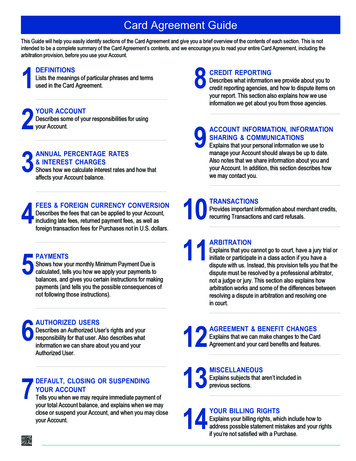
REMstar Pro C-Flex PROVIDER GUIDEIMPORTANT! Remove this guide before giving the device to the patient. Only medical professionals should adjust pressure settings.This guide provides you with instructions on how to access and navigate the provider screens used to modify device settings.Refer to the User Manual for more information.Note: The screens shown throughout this guide are examples only. Actual screens may vary slightly.Accessing the Provider Mode ScreensAccessing provider mode unlocks settings that cannot be modified by the user. To access provider mode:1. Supply Power to the device. First, plug the socket end of the AC power cord into the power supply. Then plug the prongedend of the AC power cord into an electrical outlet that is not controlled by a wall switch. Finally, plug the power supply cord’sconnector into the power inlet on the back of the device.2. Once the device is powered, the Home Screen appears, shown below. Turn the wheel to toggle between the four optionsand highlight tupHome ScreenNote: “Flex” shown above will display as the current Flex mode.3. Once “ Setup” is highlighted, press and hold both the Control Wheel and the Ramp Buttonon the device for at least5 seconds.4. You will hear a quick double beep and the Provider Mode Screen will appear, shown below. You are now in provider mode.Provider Screen-1-
Navigating the Provider Mode ScreensTo navigate these display screens:Turn the wheel to toggle between options and settings on the screen. Press the wheel to choose an option or setting that ishighlighted. If you choose “Back” on any screen, it will take you back to the previous screen.Note: Choose “EXIT” from the Provider Screen will exit provider mode and the device will return to the Home Screenin the patient mode.Note: Provider mode will time out after 1 minute of inactivity and automatically exit the provider mode and return to theHome Screen in the patient mode.Provider Mode Screen DescriptionsThe following sections will describe the options available under the 3 choices from the Provider Screen (Reminder, Setup, and Info).Reminder ScreenReminderFrom the Provider screen, highlight “Reminder” and press the wheel. The following Reminder screen will appear.BackReminder off 30 90180 270 365Reminder Screen Reminder - You can set a reminder on this screen that will let patients know when it is time to perform a certain task,such as replacing the mask.You can select one of the following settings: Off (no reminder is set), or you can set the deviceto display a reminder after 90, 180, 270, or 365 days.Note: You can set a specific patient reminder message using the Encore Pro software, and put this message on the SDCard or send it to the patient’s device via a modem.Setup ScreenSetupFrom the Provider screen, highlight “Setup” and press the wheel. The following Setup screen will appear.BackCPAP pres4.0 - 20.0Flex typenone C-Flex C-Flex Flex123Tubing type lock on offTubing type15 22SYSTEM ONE resistance 0 X1 X2 X3 X4 X5Lock SYSTEM ONEon offRamp time0:00 - 0:45Ramp start4.0 - (CPAP pres)SYSTEM ONE humidificationHumidifier0 1 2 3 4 5Auto onon offAuto offon offMask alerton offHumidifier LED backlight on offShow AHI/leak/PB on offLanguageEN ESBackSetup ScreenNote: The screen will only show 4 lines at a time. As you rotate the wheel to toggle over different options the screenwill slide up and down accordingly. If the text is too long to completely fit on the screen, it will scroll horizontally acrossthe screen when highlighted.-2-
CPAP pres - This screen displays the current CPAP pressure setting. You can adjust the setting from 4 cm H2O to 20 cm H2O. Flex type - This screen displays the comfort mode setting. You can select None, C-Flex, or C-Flex . Flex - You can modify the Flex setting (1, 2 or 3) on this screen if you enabled Flex. The setting of “1” provides a smallamount of pressure relief, with higher numbers providing additional relief.Note: The patient also has access to this setting, if Flex is enabled. Tubing type lock - If available on your device, this enables you to lock the Tubing type setting if you do not want thepatient to change it.Note: If you lock this setting, the device defaults to a setting of 22, and the patient will not see the Tubing type setting. Tubing type - If available on your device, this setting allows you to select the correct size diameter tubing that you areusing with the device. You can choose either (22) for the Respironics 22 mm tubing, or (15) for the optional Respironics15 mm tubing. SYSTEM ONE resistance () - This setting allows you to adjust the level of air pressure relief based on the specificRespironics mask. Each Respironics mask may have a “System One” resistance control setting. System One resistancecompensation can be turned off by choosing the setting “0”.Note: The patient also has access to this setting, if Lock SYSTEM ONE is off. Lock SYSTEM ONE - This enables you to lock the “System One” resistance control setting if you do not want thepatient to change it.Note: If you lock this setting, the patient will see a “lock” icon next to the setting. Ramp time - When you set the ramp time, the device increases the CPAP pressure from the value set on the RampStarting Pressure screen to the CPAP pressure setting over the length of time specified here.Note: If the CPAP pressure is set to 4 (the minimum setting), this screen will not display.Note: If the Ramp time is set to 0, Ramp start will not display. Ramp start - This displays the ramp starting pressure. You can increase or decrease the ramp starting pressure in 0.5 cmH2O increments. This is only available if Ramp time has been set to 0 and CPAP pressure 4 cm H2O. SYSTEM ONE humidification - System One humidity control maintains a consistent mask humidity by monitoring andadjusting for changes in room temperature and room humidity. You can enable or disable this feature. If the System Onehumidity control has been disabled, the classic style of basic temperature controlled heated humidification will be used.This will only display if the humidifier is attached. Humidifier - This setting allows you to choose the desired humidity setting: 0, 1, 2, 3, 4 or 5. If the System One humiditycontrol has been disabled, the classic style of basic temperature controlled heated humidification will be used and thedisplay will show: 0, C1, C2, C3, C4 or C5 for these settings. This will only display if the humidifier is attached. Please referto the humidifier manual if using a humidifier. Auto on - You can enable or disable this feature if you want the device to automatically turn the airflow on whenever thepatient applies the interface (mask) to their airway. Auto off - You can enable or disable this feature if you want the device to automatically turn the airflow off whenever thepatient removes the interface (mask) from their airway. Mask alert - You can enable or disable the mask alert setting. If this feature is enabled, the mask alert will appear on thedisplay screen when a significant mask leak is detected, and an audible alert will sound. Humidifier LED Backlight (Ramp Backlight) - You can enable or disable the LED backlight for the humidifier numbersettings and Ramp button on the device.Note: If the humidifier is not attached, this feature will display as “Ramp Backlight” and control the LED backlight for theRamp button only.Note: If the Humidifier LED Backlight is enabled or disabled, the humidifier icon will always remains on (if humidifier isattached and heat is being applied), but will dim after 30 seconds of inactivity. Show AHI/leak/PB - You can select whether or not the Apnea/Hypopnea index, System Leak averages, and PeriodicBreathing averages are displayed on the Patient Info screens. Language - This feature allows you to choose which language to display on the interface. You can choose English (EN) orSpanish (ES).-3-
Info ScreenInfoFrom the Provider screen, highlight “Info” and press the wheel. The following Info screen will appear.BackPhone-inCompliance VICTherapy hoursBlower hoursDays 4Large leakAHIPeriodic breathingReset dataMachine hoursBackInfo ScreenNote: The screen will only show 4 lines at a time. As you rotate the wheel to toggle over different options the screen willslide up and down accordingly. Phone-in - This screen displays the total therapy hours for the device, the total blower hours, and the total numberof days used when the sessions were greater than 4 hours since the device was last reset. This screen also displays acompliance check number you can use to validate that the data provided to you is the data taken from this screen. Compliance VIC (Visual Inspection Check) - This screen displays the start day and the total number of days usedwhen the sessions were greater than 4 hours. This screen also displays a check code number you can use to validate thatthe data provided to you is the data taken from this screen. Therapy hours - The device is capable of recognizing the difference between the time the patient is actually receivingtherapy and the time when the blower is simply running. This screen displays the average amount of time the patientis actually receiving therapy on the device over a 7 day and 30 day time frame (provided the device has at least 7 or 30days of data respectively). If the device has only 5 days of data to use for the calculation, the 5 day average value will beseen under the 7 day display. Blower hours - This screen displays the number of hours that the blower has been active over the life of the device. Days 4 - This screen displays the cumulative number of device therapy sessions that exceeded 4 hours over a 7 day and30 day time frame. Large leak - During any given night, the device recognizes the percentage of time the patient was experiencing what itdeemed to be a large leak. Large leak is defined as the level of leak that is so large, it is no longer possible to determinerespiratory events with statistical accuracy. This screen displays the average of these individual nightly values ofpercentage of time in large leak over a 7 day and 30 day time frame (provided the device has at least 7 or 30 days of datarespectively). If the device has only 5 days of data to use for the calculation, the 5 day average value will be seen under the7 day display. AHI - The device accumulates individual Apnea/Hypopnea indices (AHI) for each session the patient used the device. Thisscreen displays the average of these individual nightly AHI values over a 7 day and 30 day time frame (provided the devicehas at least 7 or 30 days of data respectively). If the device has only 5 days of data to use for the calculation, the 5 dayaverage value will be seen under the 7 day display. Periodic Breathing - During any given night, the device recognizes the percentage of time the patient was experiencingperiod breathing. This screen displays the average of these individual nightly values of periodic breathing over a 7 day and30 day time frame (provided the device has at least 7 or 30 days of data respectively). If the device has only 5 days of datato use for the calculation, the 5 day average value will be seen under the 7 day display. Reset data - This screen allows you to erase all 7 and 30 day averages, compliance data, therapy hours and patientinformation on the device. Make sure that “Reset data” is highlighted on the info screen. Press and hold both the controlwheel and the ramp buttonfor at least 5 seconds. The device will beep once signifying that the data has been reset.Note: Machine hours are not erased. Machine hours - This screen displays the amount of time that the machine has been active over the life of the device.Note: Therapy hours and blower hours can be reset for new patients. Machine hours are not erased.-4-
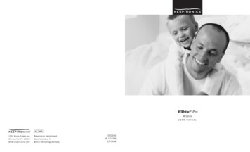
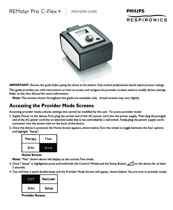
C-Flex Comfort FeatureThe device consists of a special comfort feature called C-Flex. WhenC-Flex is enabled, it enhances patient comfort by providing pressurerelief during the expiratory phase of breathing. In the diagram, thedashed line represents normal CPAP therapy in comparison to the boldline representing C-Flex. C-Flex levels of 1, 2, or 3 progressively reflectincreased pressure relief.C-Flex pressure relief is determined by the C-Flex setting and theamount of patient flow. C-Flex returns to the set pressure by the end ofexhalation, when the airway is most vulnerable to closure.Note: The patient also has access to this setting, if C-Flex is enabled.C-Flex Comfort FeatureThe device consists of a special comfort feature called C-Flex . WhenC-Flex is enabled, it enhances patient comfort in three ways: 1) bysmoothing the transition between the end of inhalation and the beginningof exhalation, 2) by providing significant pressure relief during thebeginning of exhalation, and 3) by reaching an end exhalation pressure ofno more than 2 cm H2O below the high point of inspiration.In the diagram, the dashed line represents CPAP pressure in comparisonto the bold line representing C-Flex . C-Flex levels of 1, 2, or 3progressively reflect increased pressure relief during the beginning ofexhalation.With C-Flex , the level of pressure relief at the beginning of exhalation is determined by the C-Flex setting and the amountof patient flow in any one breath.Note: The patient also has access to this setting, if C-Flex is enabled.Note: C-Flex transitions from no C-Flex at 4.0 cm H2O to full C-Flex at 6 cm H2O. C-Flex is top limited at20.0 cm H2O pressure.RampThe device is equipped with a linear ramp feature that allows patients toreduce the pressure and then gradually increase (ramp) the pressure tothe prescription pressure setting so they can fall asleep more comfortably.The diagram illustrates how the ramp feature works.-5-
Event DefinitionsThe REMstar Pro C-Flex monitors breathing and detects apneas and hypopneas.EventDefinitionObstructed AirwayApnea / ClearAirway ApneaDetectionAn apnea is detected when there is an 80% reduction in airflow from baseline for at least 10 seconds or if there is noairflow detected for 10 seconds.RERADetectionRERA (Respiratory effort-related arousal) is defined as an arousal from sleep that follows a 10 second or longersequence of breaths that are characterized by increasing respiratory effort, but which does not meet criteria for anapnea or hypopnea. Snoring, though usually associated with this condition need not be present. The RERA algorithmmonitors for a sequence of breaths that exhibit both a subtle reduction in airflow and progressive flow limitation. Ifthis breath sequence is terminated by a sudden increase in airflow along with the absence of flow limitation, and theevent does not meet the conditions for an apnea or hypopnea, a RERA is indicated.Periodic BreathingA persistent waning and waxing breathing pattern which repeats itself between 30 and 100 seconds. The nadir ofthe breathing pattern is characterized by at least a 40% reduction in airflow from an established baseline flow. Thepattern must be present for several minutes before it can be identified as periodic breathing.During the apnea, one or more pressure test pulses are delivered by the device. The device evaluates the response ofthe patient to the test pulse(s) and assesses whether the apnea has occurred while the patient has a clear airway oran obstructed airway. The airway is determined to be clear if the pressure test pulse generates a significant amount offlow; otherwise the airway is determined to be obstructed.No therapy adjustments are made in response to periodic breathing.Flow LimitationDetectionThe device looks for relative changes in the peak, flatness, roundness, or shape (skewness) of the inspiratory portionof the airflow waveform. These changes are observed both over a short period of time (groups of 4 breaths) andover a long period of time (several minutes). Statistical measures are used to help minimize false event detectionwhile allowing the device to be sensitive to even small changes.HypopneaDetectionA hypopnea is detected when there is an approximately 40% reduction in airflow from baseline for at least 10seconds.SnoreDetectionVibratory snore is detected when a specific frequency is detected during the inspiratory portion of the patient’sbreath.Vibratory snore is disabled at pressures greater than 16 cm H2O.Cleaning for Multiple UsersWARNING: If you are using the device on multiple users, discard and replace the bacteria filter each time the device isused on a different person.If you are using the device on multiple users, complete the following steps to clean the device before each new user.1. Unplug the device before cleaning.2. Clean the outside of the device only. Use a cloth with one of the following cleaning agents to clean the exterior of the device: Mild Detergent 70% Isopropyl Alcohol DisCide Towelettes 10% Chlorine Bleach solution3. Allow the device to dry completely before plugging in the power cord.-6-
Verifying the PressureWARNING: If the device fails to perform within the stated specifications, have the system serviced by a qualifiedRespironics-approved service facility.If part of your patient setup procedure is to verify actual pressure with a manometer, please use the following instructions toensure that the device is functioning properly. You will need the following equipment to verify the pressure:Respironics Pressure Calibration Kit includes: Respironics Whisper Swivel II Respironics O2 Enrichment Final Assembly Closed end cap Respironics flexible tubing Pressure tubing Respironics Digital Manometer or equivalentMinimum Specifications:0 - 25 cm H2O (or better) 0.3 cm H2O accuracy 0.1 cm H2O resolution Foam filterTo verify the pressure, complete the following steps:1. Install the foam filter into the back of the device.2. With the device unplugged, connect the system as illustrated in the diagram.3. Turn the manometer on. If it does not display a reading of zero, adjust the manometer to calibrate it. If the manometer hasvariable settings for devices, set it to cm H2O.4. Supply power to the device then place the device in provider mode.5. Set the therapy parameters according to the patient specific data.6. Set the device to the specific pressure value for the patient.7. Verify that the pressure setting matches the pressure displayed on the manometer. If the pressure setting does not matchthe measured value for the device, contact Respironics or an authorized service center to have the device serviced.Note: Output pressures may vary at local altitude and barometric pressure. Because of these factors, devices may slightlyvary in output pressure over the range of the altitude settings.8. Set up the remaining parameters and exit provider mode. The unit is ready for patient use.-7-
EMC InformationGuidance and Manufacturer’s Declaration - Electromagnetic Emissions – This device is intended for use in the electromagneticenvironment specified below. The user of this device should make sure it is used in such an environment.Emissions TestComplianceElectromagnetic Environment - GuidanceRF emissionsCISPR 11Group 1The device uses RF energy only for its internal function. Therefore, its RF emissionsare very low and are not likely to cause any interference in nearby electronicequipment.RF emissionsCISPR 11Class BThe device is suitable for use in all establishments, including domestic establishmentsand those directly connected to the public low-voltage power supply network.Harmonic emissionsIEC 61000-3-2Class AVoltage fluctuations/Flicker emissionsIEC 61000-3-3CompliesGuidance and Manufacturer’s Declaration - Electromagnetic Immunity – This device is intended for use in the electromagneticenvironment specified below. The user of this device should make sure it is used in such an environment.Immunity TestElectrostaticDischarge (ESD)IEC 60601 TestLevelCompliance LevelElectromagnetic Environment Guidance 6 kV contact 6 kV contactFloors should be wood, concrete or ceramic tile.If floors are covered with synthetic material, therelative humidity should be at least 30%. 8 kV air 8 kV air 2 kV for power supply lines 2 kV for supply mains 1 kV for input-output lines 1 kV for input/output lines 1 kV differential mode 1 kV differential mode 2 kV common mode 2 kV for common mode 5% UT( 95% dip in UT) for0.5 cycle40% UT(60% dip in UT) for5 cycles70% UT (30% dip inUT) for 25 cycles 5% UT ( 95% dip in UT) for5 sec 5% UT( 95% dip in UT) for0.5 cycle40% UT(60% dip in UT) for 5 cycles70% UT (30% dip in UT) for25 cycles 5% UT ( 95% dip in UT) for5 secMains power quality should be that of a typicalhome or hospital environment. If the user ofthe device requires continued operation duringpower mains interruptions, it is recommendedthat the device be powered from anuninterruptible power supply or a battery.3 A/m3 A/mPower frequency magnetic fields should be atlevels characteristic of a typical location in atypical hospital or home environment.IEC 61000-4-2Electrical fastTransient/burstMains power quality should be that of a typicalhome or hospital environment.IEC 61000-4-4SurgeIEC 61000-4-5Voltage dips, shortinterruptions and voltagevariations on power supplyinput linesIEC 61000-4-11Power frequency (50/60 Hz)magnetic fieldIEC 61000-4-8NOTE: UT is the a.c. mains voltage prior to application of the test level.-8-Mains power quality should be that of a typicalhome or hospital environment.
Guidance and Manufacturer’s Declaration - Electromagnetic Immunity – This device is intended for use in the electromagneticenvironment specified below. The user of this device should make sure it is used in such an environment.Immunity TestIEC 60601 Test LevelCompliance LevelElectromagnetic Environment -GuidancePortable and mobile RF communications equipment should beused no closer to any part of the device, including cables, than therecommended separation distance calculated from the equationapplicable to the frequency of the transmitter.Conducted RFIEC 61000-4-63 Vrms150 kHz to 80 MHzRadiated RFIEC 61000-4-33 V/m80 MHz to 2.5 GHz3 VrmsRecommended separation distanced 1.2d 1.2d 2.380 MHz to 800 MHz800 MHz to 2.5 GHz3 V/mwhere P is the maximum output power rating of the transmitter inwatts (W) according to the transmitter manufacturer and d is therecommended separation distance in meters (m).Field strengths from fixed RF transmitters, as determined by anelectromagnetic site surveya, should be less than the compliance level ineach frequency range.bInterference may occur in the vicinity of equipment marked with thefollowing symbol:NOTE 1 At 80 MHz and 800 MHz, the higher frequency range applies.NOTE 2 These guidelines may not apply in all situations. Electromagnetic propagation is affected by absorption and reflection from structures,objects, and people.aField strengths from fixed transmitters, such as base stations for radio (cellular/cordless) telephones and land mobile radios, amateur radio,AM and FM radio broadcast and TV broadcast cannot be predicted theoretically with accuracy. To assess the electromagnetic environmentdue to fixed RF transmitters, an electromagnetic site survey should be considered. If the measured field strength in the location in whichthe device is used exceeds the applicable RF compliance level above, the device should be observed to verify normal operation. If abnormalperformance is observed, additional measures may be necessary, such as re-orienting or relocating the device.bOver the frequency range 150 kHz to 80 MHz, the field strengths should be less than 3 V/m.-9-
Recommended Separation Distances between Portable and Mobile RF Communications Equipment and This Device: The device isintended for use in an electromagnetic environment in which radiated RF disturbances are controlled. The customer or the userof this device can help prevent electromagnetic interference by maintaining a minimum distance between portable and mobile RFcommunications equipment (transmitters) and this device as recommended below, according to the maximum output power of thecommunications equipment.Rated Maximum PowerOutput of TransmitterWSeparation Distance According to Frequency of Transmitterm150 kHz to 80 MHzd 1.280 MHz to 800 MHzd 1.2800 MHz to 2.5 GHzd .87.3100121223For transmitters rated at a maximum output power not listed above, the recommended separation distance d in meters (m) can be estimated usingthe equation applicable to the frequency of the transmitter, where P is the maximum output power rating of the transmitter in watts (W) accordingto the transmitter manufacturer.Note 1: At 80 MHz and 800 MHz, the separation distance for the higher frequency range applies.Note 2: These guidelines may not apply in all situations. Electromagnetic propagation is affected by absorption and reflection from structures,objects, and people.- 10 -
- 11 -
10582841057391 R03JR 9/24/2010EN-DOM- 12 -
REMstar Pro C-Flex PROVIDER GUIDE - 2 - Navigating the Provider Mode Screens To navigate these display screens: Turn the wheel to toggle between options and settings on the screen. Press the wheel to choose an option or setting that is highlighted. If you choose "Back" on any screen, it will take you back to the previous screen.