Transcription
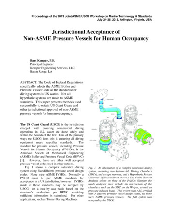
Proceedings of the 2013 Joint ASME/USCG Workshop on Marine Technology & StandardsJuly 24-25, 2013, Arlington, Virginia, USAJurisdictional Acceptance ofNon-ASME Pressure Vessels for Human OccupancyBart Kemper, P.E.Principal EngineerKemper Engineering Services, LLCBaton Rouge, LAABSTRACT: The Code of Federal Regulationsspecifically adopts the ASME Boiler andPressure Vessel Code as the standards fordiving systems in US waters. Not allhyperbaric systems are made to ASMEstandards. This paper presents methods usedsuccessfully to obtain US Coast Guard andother jurisdictional approval of non-ASMEpressure vessels for human occupancy.The US Coast Guard (USCG) is the jurisdictioncharged with ensuring commercial divingoperations in U.S. water are done safely andwithin the bounds of the law. One of the primaryways the USCG does this is ensuring all divingequipment meets specified standards.Thestandard for pressure vessels, including PressureVessels for Human Occupancy (PVHOs), is theAmerican Society of Mechanical Engineering(ASME) Boiler and Pressure Vessel Code (BPVC)[1]. However, there are other well acceptedpressure vessel codes used in other nations.Fig. 1 shows a complex saturation divingsystem using five different pressure vessel designcodes. None were ASME PVHOs. Normally aPVHO must be per ASME standards foracceptance in a US jurisdiction; however, PVHOsmade to those standards may be accepted byUSCG on a case-by-case basis based on thestructure’s evaluation per BPVC providingsufficient information is submitted. For otherapplications, such as Tunnel Boring MachinesFig. 1. An illustration of a complex saturation divingsystem, including two Submersible Diving Chambers(SDCs), and escape manway, and a Hyperbaric RescueChamber (lifeboat hull not shown.) The Finite ElementAnalysis colors on three of the PVHOs illustrate theloads analyzed must include the interactions of thechambers, such as the SDC on the Wetpot, as well aspressure-induced loads. This system was ABS certifiedwith 5 different pressure vessel design codes, but nonewere ASME pressure vessels. The full system wasaccepted by the USCG.
Jurisdictional acceptance of non-ASME PVHOs / 2using saturated atmosphere operations, the statepressure vessel board may be the jurisdictionalauthority.Jurisdictional needs vary, so isimportant to understand the jurisdiction’srequirements as well as the specific application.For diving and medical systems, citing ASMEBPVC includes the code for new construction(ASME PVHO-1) [2] and the in-service guidelinesfor acrylic windows (ASME PVHO-2 [3]. Inaddition, there are several federal regulations [4, 5,6] that modify the ASME codes as well as putforth other requirements. The definitions in Ref. 4specify BPVC “Section VIII, or an equivalentcode which the employer can demonstrate to beequally effective.”Based on experience, the USCG will accept anon-ASME pressure vessel as “equivalent” if theuser demonstrates the vessel was properlymanufactured, tested, certified, and maintainedaccording to other codes and regulations and thatpressure vessel meets ASME code, even at adowngraded pressure. The concept is simple, butthe execution requires more attention to detail thanengineering work for new PVHO design andconstruction. The methods offered in this paperare based on experience but do not reflect anyreview or endorsement by the USCG or any otherauthority. Each submission to a jurisdiction isevaluated on its own merits.CodesThe Code of Federal Regulations (CFR)establishes the criteria for operating divingsystems in US waters. It specifies the designcodes to be complied with, such as BPVC andPVHO, as well as changes and additions to thecode that must also be complied with. Anexample of this 46 CFR 54.01-35, which modifiesBPVC section UG-25 by specifying additionalcorrosion parameters not in ASME codes. A goodstarting reference is App. B of the Coast GuardDiving Policies and Procedures, “CommercialDiving Regulatory Checklist.” [7] However, athorough review of cited CFRs is recommended toensure full compliance with the currentregulations. Regulations may change. It’s alsorecommended to have a thorough understanding ofthe codes and regulations the PVHO currentlymeets in order to use existing inspections andcertifications to show equivalency with the CFRspecified requirements.The window requirements in PVHO are critical.While there are numerous pressure vessel codes,ASME PVHO was the first code to addresswindows. However, since other authorities haveadopted ASME PVHO, the windows and windowseats designed to other codes typically complywith PVHO. As long as the windows and windowseats comply with ASME PVHO, other variationsfrom ASME codes can often be addressed bytesting and detailed engineering analysis.Fig. 2. Illustration from BPVC Section VIII, UG-42,showing there should be a full radius of clear metalaround each opening in the shell or head. This appliesregardless of the thickness of the ring within theopening.Fig. 3 Cross section of a Submersible Diving Chamber(SDC), also known as a Diving Bell. Windows areneeded to safely operate. However, the distancebetween head openings should be more than the radiusof window plus the radius of the manway in order tosatisfy the letter of the code. Stress analysis canresolve these structural geometry issues.
Jurisdictional acceptance of non-ASME PVHOs / 3One of the most common differences betweendifferent national pressure vessel codes isgeometry. Minimum allowable knuckle radius,allowable distances between fittings, weld types,and other design details can vary from code tocode. There are also features common to diving,such as bottom side viewports in diving bell heads,which conflict with allowable locations anddistances. (Figs. 2 and 3). Downrating themaximum working pressure for the system canresolve some of these specific issues as well asincrease the overall safety of the system.A proven approach is to use a code calculationpackage such as COMPRESS and PVElite toprovide a comprehensive set of “by rules” SectionVIII calculations for Division 1 or Division 2.This addresses a common pitfall of usingspreadsheets or less complete means to presentcode calculations, which may selectively show thecompliantaspectswhileomittingthenoncompliant features. The code package willprovide a list of noncompliant features and othershortfalls. While the shortfalls still need to beaddressed, everything that is not on the shortfalllist complies with the BPVC.Fig. 4 A 12m (40ft) diameter Japanese-built TunnelBoring Machine for a worksite in Washington State.The PVHO was not designed nor built to ASMEstandards The state pressure vessel board required adetailed engineering review to approve the PVHOinstalled in this TBM. .Tunnel Boring Machines (TBMs)The tunneling industry recently began usingpressurized drill faces to control the TBM cuttinghead interface with the water/soil/rock beingdrilled. This replaces using large caissons topressurize an entire tunnel. In order to operate andmaintain the TBM at depth, the operators “drydive,” or work in a pressurized, gas controlledenvironment similar to what the diving industryuses. While there is little else in common withdiving, the physiology of pressurized atmosphereand the life-safety issues regarding structuralintegrity and systems reliability is the same forboth applications. The Occupational Safety AndHealth Administration (OSHA) issued a Letter ofInstruction in 2010 stating that “OSHA recognizesASME PVHO-1 standards as specifying theconstruction industry’s usual and customarypractice for preventing death and serious injuryassociated with pressurized work places;therefore, OSHA would enforce (ASME PVHO-1)under the general-use clause.” [8]Fig. 5. Solid model of the Tunneling Safety Lock usedwith the TBM in Fig. 4. This shows the drilling side.Workers enter through one of two manways to the leftand use the tunnel to the right to reach the controlroom. The cylinder is split in half along the dashedlines by a vertical bulkhead with an internal door.This allows half the cylinder to be used to decompressoutbound workers while inbound workers enter on theother side. Fig. 6 shows the internal geometry.TBM applications have their own challenges.TBMs are often custom built for a specific job.This space available for the PVHO is often limitedso shapes and features not common in normalpressure vessels are common. These PVHOs aresubject to more shock and vibration than any otherPVHO application. Currently the majority of
Jurisdictional acceptance of non-ASME PVHOs / 4TBM PVHOs are not designed to ASME code,despite the OSHA Letter of Instruction [8]. Whilesome jurisdictions will allow for equivalency asthe USCG does, others such as New York Statewill not. This can be further complicated by thetunnel pathway, which can cross ion is required to address alljurisdictional constraints.Finite Element AnalysisA successful approach to address the shortfallsfrom the code calculations is using Finite ElementAnalysis (FEA) per the “by analysis” section ofBPVC, Section VIII, Div. 2 [1]. This allows amore free-form design method providing itproperly applies more rigorous engineeringanalysis. Non-conforming structural geometries,such as small knuckle radii or windows too closeto hatchways, can be computationally modeledand analyzed to demonstrate the stresses arewithin allowable limits. Traditional calculationsand conventional code calculation packages areunable to provide these detailed results, such asshown in Fig. 6.Fig. 6. A stress plot of the Tunneling Safety Lock fromFig. 5. The interior vertical bulkhead as well as theexternal door (left) and internal door are clearlyshown. By inspection, the external door shown to theleft is less than one door diameter from the bulkhead,resulting in elevated coupled stresses between the twostructures. The flat bulkhead is reinforced withstructure steel on both sides to account for differentialpressurization.These features are not standardpressure vessel structures and have complex stressinteractions.A potential pitfall is addressing only part ofthe “design by analysis” requirements.Anexample is providing the analysis to show globalplastic collapse will not occur while ignoringbuckling and fatigue. While it may seem intuitivethe required analyzes are not needed, failing toaddress code-specified requirements can raiseissues with the reviewing engineer.FEA can also be used to address the divingPVHO-specified “marine loads” for shipboardPVHO’s. Marine loads must be either calculatedbased on expected service at that location in theship or be assumed to be an additional load of1g/2g/1g load in the x/y/z directions, with “y”being vertical. These loads are not part of astandard code calculation package. FEA can alsobe used to address localized issues, such as pittingand local corrosion, as well as system-wide issuessuch as loads on the anchorages due to tunnelingor shipboard movement and vibration.The reviewing engineer should proactivelyassess all loads that may be applicable in order toreduce the likelihood of rejection by thejurisdiction. Section UG-22 in Div. 1 [1] has aspecified list of considerations, In Div. 2 it isparagraph 4.1.5.3 for “design by rules” and Table5.3 coupled with paragraph 5.1.1.2 for “design byanalysis” [1]. Both divisions have tables of loadcombinations that must be addressed.MaterialsIf a PVHO is made to a non-ASME code, it islikely the cited material is not an ASME materialper Section II of the BPVC. However, it is oftenpossible to compare chemical makeup andrequired mechanical properties to determine anequivalent ASME pressure vessel material. Oncean equivalent material is established the tables inSection II provide the allowable stress levelsneeded for calculations and computer modeling.Not all materials have an ASME equivalent.However, Section II [1] has guidelines to establishallowable stress levels.Once these areestablished, Section VIII, Div. 2 providesmethodology for developing stress/strain curves,fatigue curves, and other design data needed forcalculations and computer modeling.Thesecurves are more conservative than the literaturevalues for these properties. Simply providing labtests or literature values for pressure vessel
Jurisdictional acceptance of non-ASME PVHOs / 5materials without addressing code requirementscan pose an issue with the reviewing engineer.It must be noted simply determining theallowable stress levels is not sufficient. Heattreatment properties, OEM caveats of material use,and other factors must be accounted for. Thereviewing engineer must pay close attention todetail in order to determine what the otherpertinent properties of the material are. Manyjurisdictions will not allow a variance in materialsor will require substantial documentation beforeconsidering a non-ASME material.Maintenance and TestingMaintenance logs, inspections, hydrostatictesting, x-rays of welds, and full design drawingsare some of the required items outlines in theCFRs. Unfortunately, these documents are notalways properly maintained when PVHOs arebought and sold. Manufacturers are not requiredto keep records for the life of the vessel and maygo out of business. The original manufacturercannot always be relied upon for this information.If the original documents are not available, thecurrent as-built state must be established anddocumented, to include full drawings. In somecases laser-based surveys have been used to helprecreate missing drawings. Full photographicsurveys to document PVHO conditions and systemconfiguration helps establish the PVHO’s currentstate. Ultrasonic testing surveys are highlyrecommended to establish key thicknesses andverify weld integrity. Witnessed hydrotests are akey CFR-specified requirement as well arerequired by ASME code.Much of this information is needed to do codecalculations and engineering analysis. Divingsystems certified to a Classing Society such as theAmerica
ASME PVHO-1 standards as specifying the construction industry’s usual and customary practice for preventing death and serious injury associated with pressurized work places; therefore, OSHA would enforce (ASME PVHO-1) under the general-use clause.” [8] Fig. 5. Solid model of the Tunneling Safety Lock used with the TBM in Fig. 4. This shows the drilling side. Workers enter through one .