Transcription
PROPHECY INFINITY Pre-Operative Navigation GuidesSURGIC A L T ECHNIQUE
SURGEON DESIGN TEAMThe PROPHECY INFINITY Total Ankle Systemwas developed in conjunction with:PROPHECY INFINITY Robert B. Anderson, MDOrthoCarolinaCharlotte, NCSURGICAL TECHNIQUEGregory C. Berlet, MDOrthopedic Foot and Ankle CenterColumbus, OHPre-Operative Navigation GuidesW. Hodges Davis, MDOrthoCarolinaCharlotte, NCSteven L. Haddad, MDIllinois Bone and Joint InstituteChicago, ILThomas H. Lee, MDOrthopedic Foot and Ankle CenterColumbus, OHMurray J. Penner, MD FRCSCProvidence Health CareVancouver, BC
ContentsChapter 14 Product Information4 PROPHECY INFINITY Alignment Guide Product Information4 Intended Use4 INFINITY Total Ankle Product Information5Indications/Contraindications6 CT Scan ProtocolChapter 27 Surgical Technique7 Tibial Alignment Guide Fluoroscopic Check Assembly8 Surgical Approach8 Tibial Alignment Guide11 Install Coronal Sizing Guide14 Drill Tibial Corners15 Tibial Bone Resection16 Talar Alignment Guide19 Talar Bone Resection20 Remove Tibial Bone Resection23 Tibial Tray Trialing and AP Sizing26 Tibial Peg Broaching27 Talar Component Sizing and Positioning29 Talar Chamfer Resections33 Polyethylene Thickness34 Talar Peg Drilling35Tibial Component Implantation38Talar Component Implantation39Polyethylene Bearing Installation44Explant Information44Postoperative ManagementAppendix A45Conversion to Standard InstrumentationAppendix B56INBONE Talar Dome Resection TechniqueAppendix C59PROPHECY INBONE Talar Dome TechniqueAppendix D68INFINITY InstrumentationAppendix E77Implant SpecificationsAppendix F78Ordering InformationProper surgical procedures and techniques are the responsibility of the medical professional. Thefollowing guidelines are furnished for information purposes only. Each surgeon must evaluate theappropriateness of the procedures based on his or her personal medical training and experience. Priorto use of the system, the surgeon should refer to the product package inserts (145283) for completewarnings, precautions, indications, contraindications and adverse effects. Package inserts are alsoavailable by contacting the manufacturer. Contact information can be found on the back of thissurgical technique and the package insert is available on the website listed: wmt.com, under thelink for Prescribing Information.Please contact your local Wright representative for product availability.3
chapterProductInformation1PROPHECY INFINITY Alignment Guide ProductInformationThese surgical instruments are designed for single use only. They aremanufactured with certain patient-specific features, which render them unusablein cases other than that for which they were designed. These surgical instrumentsare supplied clean and non-sterile, and must be sterilized before use. After use,these instruments must be properly disposed of. Please refer to the PROPHECY INFINITY Instrument package insert #146636 for instructions on the proper stepsfor processing Wright Medical disposable surgical instruments.Intended UseWright’s PROPHECY INFINITY Preoperative Navigation Alignment Guidesare intended to be used as patient-specific surgical instrumentation to assistin the positioning of total ankle replacement components intra-operativelyand in guiding the marking of bone before cutting. The PROPHECY INFINITY Preoperative Navigation Alignment Guides are intended for use with Wright’sINFINITY Total Ankle Systems and their cleared indications for use, provided thatanatomic landmarks necessary for alignment and positioning of the implant areidentifiable on patient imaging scans. The PROPHECY INFINITY PreoperativeNavigation Alignment Guides are intended for single use only.INFINITY Total Ankle Product InformationThrough the advancement of partial and total joint replacement, the surgeonhas been provided with a means of restoring mobility, correcting deformity, andreducing pain for many patients. While the prostheses used are largely successfulin attaining these goals, it must be recognized that they are manufactured from avariety of materials and that any joint replacement system, therefore, cannot beexpected to withstand activity levels and loads as would normal healthy bone. Inaddition, the system, including the implant/bone interface, will not be as strong,reliable, or durable as a natural human joint.Ankle joint replacement components consist of a talar dome, a tibial platform,and an UHMWPE component. Components are available in a variety of sizes anddesign configurations intended for both primary and revision applications.4Chapter 1Product Information
IndicationsThe INFINITY Total Ankle is indicated for patients with ankle joints damaged bysevere rheumatoid, post-traumatic, or degenerative arthritis.The INFINITY Total Ankle is additionally indicated for patients with a failedprevious ankle surgery.CAUTION: The ankle prosthesis is intended for cement use only.ContraindicationsAbsolute contraindications include:1. osteomyelitis;2. excessive bone loss at the ankle joint site;3. steroid use;4. infection at the ankle site or infections at distant sites that could migrate tothe ankle;5. sepsis;6. muscular atrophy;7. dementia;8. vascular deficiency in the ankle joint;9. skeletally immature patients (patient is less than 21 years of age at the time ofsurgery);10. cases where there is inadequate neuromuscular status (e.g., prior paralysis,fusion and/ or inadequate abductor strength), poor bone stock, poor skincoverage around the joint which would make the procedure unjustifiable;11. neuropathic joints;12. hepatitis or HIV infection;13. excessive loads as caused by activity or patient weight;14. female of childbearing age, for whom a negative pregnancy test is notobtained; and,15. neurological or musculoskeletal disease that may adversely affect gait orweightbearing.Conditions presenting increased risk of failure include:1. uncooperative patient or patient with neurologic disorders, incapable offollowing instructions;2. marked bone loss, severe osteoporosis, or revision procedures for which anadequate fit of the prosthesis cannot be achieved;3. metabolic disorders that may impair bone formation;4. osteomalacia; and,5. poor prognosis for good wound healing (e.g., decubitus ulcer, end-stagediabetes, severe protein deficiency and/or malnutrition).Prior to use of the system, the surgeon should refer to the product package insertfor complete warnings, precautions, indications, contraindications and adverseeffects. Package inserts are also available by contacting the manufacturer.Contact information can be found on the back of this surgical technique andthe package insert is available on the website listed.Chapter 1Product Information5
CT Scan ProtocolPROPHECY INFINITY Preoperative Navigation Guides are patientspecific instruments designed using patient anatomy from a CTscan of the patient’s extremity. One significant requirement fora successful case is adhering to the PROPHECY Ankle CT ScanProtocol document. Engineers at Wright Medical Technology havedetermined the necessary scanning parameters which are describedin document #008380 and can be found on our 80).In every case, please have the scanning facility follow the specificinstructions outlined in this document.PROPHECY Ankle CT Scan Protocol#008380The Centers for Medicare & Medicaid Services (CMS) established a National Coverage Determination (NCD) for CT Scans. It states, in part, the following, “Diagnostic examinationsof the head (head scans) and of other parts of the body (body scans) performed by computerized tomography (CT) scanners are covered if medical and scientific literatureand opinion support the effective use of a scan for the condition, and the scan is: (1) reasonable and necessary for the individual patient.” CTs performed prior to total jointreplacement procedures for diagnostic purposes may be considered medically necessary. In which case, the procedure should be billed using the CPT codes that accuratelydescribe the imaging procedure furnished to the patient. These same images from the diagnostic CT scan may, in turn, be further utilized for developing the personalizedcutting or navigation guides that are used in orthopaedic procedures. However, if providers perform CT scans solely for the purpose of developing personalized cuttinginstruments or guides, providers should contact the payer for billing and coverage guidance and/or the American College of Radiology with billing questions.6
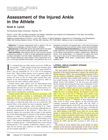
chapterSurgicalTechnique2Tibial Alignment Guide Fluoroscopic Check AssemblyTo enhance fluoroscopic visualization of the PROPHECY Tibia Alignment Guide(PROPINF or PROPINFE [EU only] ) it is recommended to place metallic markers in theguide prior to placement on the patient. Begin by using a pair of Pin Cutters (200427) toremove the sharp end of a 2.4 Steinmann Pin (200072). FIGURE 1 Note that it may behelpful to use a needle driver to retain the cut ends of the Pin. FIGURE 2 FIGURE 1 FIGURE 2Cut two ½” (or 12mm) segments of the Steinmann Pin and insert by hand into the twovertical holes in the PROPHECY Tibia Guide. FIGURE 3PROPHECY Tibia Alignment GuidePROPINFPROPINFE (EU only)Pin Cutters200427 FIGURE 3Chapter 2Surgical Technique7
Surgical ApproachMake the anterior incision centered on the ankle, directly lateral to the palpabletibialis anterior tendon and medial to the extensor hallucis longus tendon. Defineand avoid the deep peroneal nerve and anterior tibial artery. Once the nerve bundleis mobilized the anterior ankle (distal tibia and talus) is exposed with the dorsaltalonavicular joint representing the distal extent of the incision. This incision can bemodified according to the specific needs of the patient.Tibial Alignment GuidePROPHECY INFINITY alignment guides are designed to incorporate fixedosteophytes on or near the articulating surfaces, and therefore osteophytes shouldnot be removed during the surgical exposure of the ankle. However any loose bodies,specifically called out on the PROPHECY pre-operative plan, should be removedas they will not have been incorporated into the proper seating of the PROPHECY INFINITY guides.Ensure the area of the anterior tibia where the PROPHECY guide will surface matchis completely free of soft tissue and place the PROPHECY Tibia Alignment Guide inthe best fit location. FIGURE 5 Please note that the guides are designed to fit in oneand only one proper location. If the tibia guide does not sit flush against the tibia - before driving any pins intothe bone - remove the PROPHECY guide and clean off any remaining soft tissuecovering the bone. Re-evaluate the surface match fit between the guide and the bone. Repeat thesesteps until the guide sits flush against the bone in the best fit location.AnteriorPosterior FIGURE 5Note: Use the provided bone models as anadditional tactile and visual confirmationthat the tibia guide is positioned correctlyon the patient’s bone.8Chapter 2Surgical Technique
Once the Guide is in the proper location insert one 2.4 Steinmann Pin into one ofthe proximal holes of the Tibia Guide to temporarily hold it into position. FIGURE 6 Next place a Steinmann Pin though the vertical hole in the centerhandle of the Guide to serve as a coronal alignment cue . FIGURE 7 FIGURE 6 FIGURE 7With the Tibia Guide held in place, take an AP fluoro image to confirm that thetibial guide is in the correct orientation. To obtain a true AP view rotate the ankle(or conversely the c-arm) until the long Pin lines up between the two short Pins. FIGURE 8 This image should correspond to the “Anterior View” tibial alignmentguide image in the PROPHECY Pre-Op Plan. FIGURE 9Pre-Op PlanAnterior View FIGURE 8Chapter 2Surgical Technique FIGURE 99
Be sure to center the ankle on the fluoro projection screen to minimize the risk ofparallax imaging error.If the intra-op image is significantly different that the pre-op plan remove theTibia Guide as well as any Pins holding it in place. Ensure the periosteum has beencleaned from the tibia, and that skin retractors are effectively keeping all other softtissues from interfering with the Guide. It may also be beneficial to place the footinto slight plantarflexion and place a surgical bump under the tibia to elevate it.This allows the talus to drop away from the anterior tibia and prevent interferencewith the distal portion of the Tibia Guide.Replace the Tibia Guide and repeat the procedure for AP fluoro check, using theopposite side pin hole to temporarily secure the Guide in place.Note: By using only one pin to initially secure the Guide, adjustments can be madeto the Guide location providing a second option to pin in place without finding theoriginal pin hole.10Chapter 2Surgical Technique
Once the desired fit and alignment is confirmed, place a total of four 2.4mmSteinmann Pins through the guide and through both corticies of the tibia. FIGURE 10 Do not cut the pins at this time. Remove the PROPHECY guideby sliding it up and over the pins, leaving the pins in place. It may be helpfulto attach a Kocher clamp in the notches built into the rectangular anteriorhandle to pull the tibia guide up. FIGURE 10Coronal Sizing Guide33620032 - 33620035Install Coronal Sizing GuideSelect the appropriately sized Coronal Sizing Guide (33620032 through33620035) and slide over the two distal tibial pins. Let the Coronal SizingGuide slide down to the surface of the tibia. Next slide the PROPHECY Conversion Instrument (33600200) over the two proximal tibial pins andonto the dovetail of the Coronal Sizing Guide. FIGURE 11 Lock into positionusing the Hex Driver (E5001005). FIGURE 12PROPHECY Conversion Instrument33600200Hex DriverE5001005 FIGURE 11Chapter 2Surgical Technique FIGURE 1211
The surgeon has the option to fluoroscopically verify the size and orientationof the Coronal Sizing Guide prior to making the tibial resection. FIGURE 13To correct for parallax the Coronal Adjustment Guide contains a “pin-in-circle”feature. The C-arm should be adjusted until that the pin appears in the centerof the circle. FIGURE 14 & 15The dark outlines in the Coronal Guide represent the tibial resections as wellas the coronal profile of the tibial component. FIGURE 15 FIGURE 13CorrectTibial ProfileAlign FeatureIncorrect “Tilt” c-arm orraise/lower ankleto adjustIncorrect “Rainbow” c-armor internally/externally rotateankle to adjust FIGURE 15 FIGURE 14Refer to the PROPHECY Pre-Op Plan for verification of the resection.Note: At this point the surgeon can choose to revert back to the standardINFINITY instrumentation and surgical technique if there are any concernswith the planned resection. Refer to Appendix A for detailed instructions.12Chapter 2Surgical Technique
The surgeon may also choose to obtain a fluoroscopic lateral view of the ankleperpendicular to the installed Coronal Guide. This view is achieved when themedial and lateral pins in the tibia appear as one. In this view the surgeon canverify the flexion/extension angle of the planned tibial resection. FIGURE 16Two distal pins shouldappear as one FIGURE 16Note: For instructions on how to couple the tibial and talar resections refer topage 53 – 55 in Appendix A.Chapter 2Surgical Technique13
Drill Tibial CornersUsing the Tibial Corner Drill (33600048), bi-cortically drill both proximal cornersof the tibia. FIGURE 17Tibial Corner Drill33600048Resection Guide33620052 – 33620055 FIGURE 17Remove the Coronal Sizing Guide and slide the appropriately sized ResectionGuide (33620052 through 33620055) over the distal 2.4mm Pins. FIGURE 18Note: If the surgeon chooses to intra-operatively change the planned talarimplant to a flat-cut INBONE Talar Dome instead of a chamfer-cut INFINITY Talar Dome. Refer to Appendix B.Optionally, install a 2.4mm Steinmann Pin through one of the divergent pinlocations. FIGURE 19 When using a divergent pin always use the medial option(in which the pin travels medial to lateral). This will help avoid the neurovascularbundle just behind the medial malleolus.Divergent Pin locations FIGURE 1814Chapter 2Surgical Technique FIGURE 19
Tibial Bone ResectionUsing the Pin Cutter trim the Pins flush to the surface of the Resection Guide. Leaveenough length on the divergent pin to allow its removal with a pin driver or pinpuller but short enough to allow saw blade clearance in the medial resection slot(approximately 15mm).Using the appropriate size Saw Blade and oscillating bone saw make the tibialresections only. This includes cutting though the proximal, medial and lateral slots ofthe Resection Guide.CAUTION: Do not make the talar cut at this time.Remove the divergent Steinmann Pin, then remove the Resection Guide and distaltibial Steinmann Pins. Leave the two proximal tibial Steinmann Pins. At the top of thetibial cut, use an osteotome to cut down towards the talus at approximately 60 toremove the anterior section of the tibia. FIGURES 20 and 21 Remove as much of thetibia resection as possible; at a minimum remove any anterior bone that may preventproper seating of the PROPHECY Talus Alignment Guide on the talar dome. FIGURE 20Chapter 2Surgical Technique FIGURE 2115
If the surgeon pre-operatively chose to utilize an INBONE Talar Dome insteadof an INFINITY Talar Dome refer to Appendix C.Talar Alignment GuidePlace the foot into plantar flexion for maximum exposure of the talardome. Ensure the area around the neck and dome of the talus where thePROPHECY guide will surface match is free of all soft tissue. Place thePROPHECY Talus Alignment Guide (PROFINF or PROPINFE [EU only] ) on thetalar surface in the best fit location. FIGURES 22, 23 and 24In the case of uneven talar dome cartilage wear, improved talar alignmentguide accuracy may be achieved by carefully removing the cartilage with acurette from the surface-match area of the talus prior to placing the talusalignment guide.If any portion of the tibia bone prevents the talus guide from fitting properlyon the talus, either remove more of the tibial resection or increase plantarflexion of the foot (or a combination of both).PROPHECY Talus Alignment GuidePROPINFPROPINFE (EU only) FIGURE 22AnteriorDistalNote: Use the provided bone models as anadditional tactile and visual confirmationthat the talus guide is positioned correctlyon the patient’s bone.16 FIGURE 23Anterior ViewChapter 2Surgical Technique FIGURE 24Medial-Oblique View
While holding the PROPHECY guide in place install one 2.4mm SteinmannPin through either hole on the top surface of the guide and into the dome ofthe talus to temporarily hold the guide in place. FIGURE 25 Next, install two2.4mm Steinmann Pins through the anterior pin holes of the Talus AlignmentGuide and into the talar bone. Remove the Steinmann Pin in the top of theguide. FIGURE 26 Do not cut the remaining pins at this time. Remove thePROPHECY guide by sliding it up and over the pins, leaving the pins inplace. It may be helpful to attach a Kocher clamp to the notches built into thecentral triangular feature of the talar guide to pull the guide up. FIGURE 25 FIGURE 26Note: By using only one pin to initially secure the Guide, adjustments canbe made to the Guide location providing a second option to pin in placewithout finding the original pin hole.Chapter 2Surgical Technique17
The surgeon has the option to fluoroscopically verify the proximal/distallocation and flexion/extension angle of the talar component prior to talarresection. Obtain a true lateral view by aligning the c-arm so that both talarSteinmann Pins appear as one. FIGURE 27 The proximal talar resection (whitedashed line) will be parallel to and approximately 2mm proximal to the top ofthe Steinmann Pin. FIGURE 28 FIGURE 27 FIGURE 28In addition the surgeon can compare to images in the PROPHECY Pre-Op Plan to verify accuracy of the talar guide. FIGURES 29 and 30Pre-Op Plan FIGURE 2918Chapter 2Surgical Technique FIGURE 30
Talar Bone ResectionChoose the appropriately sized INFINITY Resection Guide, position the 2 talarpin holes over the 2 pins from the PROPHECY Talus Alignment Guide and slidedown to the anterior surface of the talar dome. FIGURE 31 The ResectionGuide will not necessarily be the same size used in the tibial resection. Consultthe PROPHECY pre-op plan for confirmation.Note: At this point the surgeon still has the option to intra-operativelychange to an INBONE flat-cut talar resection. Refer to Appendix B fordetails on using the INBONE Talar Resection Guide to translate the talar pinlocations and make the desired resection.Insert two additional 2.4mm Steinmann pins into the medial and lateralgutters for protection of the malleoli. FIGURE 32 Use the Pin Cutter to cut theSteinmann pins close to the surface of the Resection Guide.Gutter locations FIGURE 31 FIGURE 32Care must be taken to ensure that the placement of the gutter pins does notunintentionally cause a shift in the position of he Resection Guide. In addition,any unintentional pressure applied to the Resection Guide by the soft tissueenvelope or retractors may cause it to shift, leading to an inaccurate resection.Using the appropriate Saw Blade and oscillating bone saw make the talarresection (distal slot of the Resection Guide).CAUTION: It may be necessary to manually hold the Resection Guide ontothe bone as excessive vibration from the saw can cause the Guide to moveanteriorly and disengage from the pins.Remove the Resection Guide. Check that the talar resection is complete byusing a 1/2 inch osteotome. Complete the cut if necessary and gently lever theresected dome out anteriorly.Chapter 2Surgical Technique19
Remove Tibial Bone ResectionOptionally, to facilitate removal of the remaining posterior tibia, the CornerChisel (33600058) and a mallet can be used to finish off bone cuts in theproximal corners of the resected tibia. FIGURE 33 The Corner Chisel is lasermarked to indicate the anterior to posterior depth of the various size tibialtrays.CAUTION: Care must be taken to ensure that the Corner Chisel does notpenetrate too deeply, as neurovascular injury may occur. Do not rely solelyon the depth indications on the Chisel to determine resection depth. If unsure,utilize a lateral fluoroscopic image to confirm proper depth of the chisel. FIGURE 33Corner Chisel3360005820Chapter 2Surgical Technique
Using a pin driver, insert the Bone Removal Screw (IB200051) into the resectedtibial bone. Attach the Ratcheting Handle (44180025) to the Bone RemovalScrew to aid in removing the remaining tibial section through traction. FIGURE 34 FIGURE 34Insert the 90 Posterior Capsule Release Tool (IB200050) into the joint space anduse to free up the posterior capsule soft tissues attachments to the resectedtibia. FIGURES 35 and 36Bone Removal ScrewIB200051BoneRemovalScrewRatcheting Handle44180025PosteriorCapsuleReleaseToolPosterior CapsuleRelease ToolIB200050 FIGURE 35Chapter 2Surgical Technique FIGURE 3621
A reciprocating saw or bone rasp may be used to remove any excess bone,taking care to follow the previously made cut line. Remove loose bone piecesand irrigate the joint space. FIGURE 37 FIGURE 3722Chapter 2Surgical Technique
Tibial Tray Trialing and AP SizingPlace the appropriately sized Tibial Tray Trial (33620061 through 33620065)over the two remaining tibial pins and into the resected joint space. FIGURE 38 The padded Self-Retaining Laminar Spreaders (33609012) shouldbe inserted between the Trial and the talus to ensure the Trial is seated flush.Ensure the Tibial Trial is fully seated against the anterior cortex of the tibia. FIGURE 39 Pins may be trimmed flush to the Tibial Tray Trial.Fully Seat FIGURE 38 FIGURE 39The Tibial Tray Trial is also used to check the tibial cut surfaces and ensure thatno bone fragments will impede proper positioning of the Tibial Tray. Removeexcess bone and irrigate as necessary.Tibial Tray Trial33620062 - 33620065Self-Retaining Laminar Spreaders33609012Chapter 2Surgical Technique23
The Tibial Trial allows the surgeon to determine both the optimal AP tibialcoverage and positioning through fluoroscopic evaluation. FIGURE 40For sizes 3 through 5 the surgeon has the option to choose either a standard orlong AP sized tibial tray. The notch in the Tibial Trial indicates the length of the“standard” option. FIGURE 41 and 42Tibia component sizes 1 and 2 are each available in only one AP length. Becausethey share the same ML dimension, they utilize the same Tibial Trial. Whenusing the size 1&2 Tibia Trial the full length represents the size 2 and the notchindicates the length of the size 1 option.LongStandard FIGURE 40 FIGURE 41LongTibiaStandardTibia FIGURE 4224Chapter 2Surgical Technique
The surgeon also has the option to anteriorly translate the Tibial Trial(maximum of 3mm) in order to minimize posterior overhang if desired. FIGURE 44 To adjust, insert the Hex Driver into the front of the Tibial Trialand turn clockwise. FIGURE 43 and 45Set Screw FIGURE 433mm maximumadjustmentPosteriorOverhangHex Driver FIGURE44 FIGURE 45Chapter 2Surgical Technique25
Tibial Peg BroachingCut the Steinmann Pins to the surface of the Tibial Tray Trial. Using the PosteriorTibial Peg Broach (33600069) prepare a hole in the resected tibia by malleting theBroach through the posterior opening of the Trial. FIGURE 46 Temporarily leavethe Posterior Broach in place while the two anterior holes are prepared. FIGURE 46Using the Anterior Tibial Peg Broach (33600067) prepare the two anteriorholes through the Trial. FIGURE 47 FIGURE 47After all three holes are prepared remove both Broaches and leave the TibialTray Trial in place. FIGURE 48Anterior Tibial Peg Broach33600067Posterior Tibial Peg Broach33600069 FIGURE 4826Chapter 2Surgical Technique
Talar Component Sizing and PositioningPlace the appropriately sized Talar Dome Trial (33600071 through 33600075)into the joint space. Using the Poly Insert Trial Holding Tool (IB200110) installthe appropriately sized Poly Insert Trial (33621106 through 33625512) into theTibial Tray Trial. The locking tab of the Poly Insert Trial should engage the TibialTray Trial. FIGURE 49 FIGURE 49Poly Trial Holding ToolIB200110The surgeon has two options for the Talar Dome implant size at this juncture:either the matching size for the implanted Tibial Tray, or one size smaller. It isbeneficial to assess both sizes under A/P and lateral fluoroscopic images. Pleasenote that the A/P image is critical for sizing the talar component, as the surgeon’sgoal is to minimize overhang of the talar component, and thus minimizeprosthetic impingement in the medial and lateral gutters of the ankle joint.Poly Insert Trial33621106 - 33625512Talar Dome Trial33600071 - 33600075Chapter 2Surgical Technique27
Under sagittal plane fluoroscopy ensure the posterior portion of the TalarTrial is resting on the posterior portion of the patient’s residual talus (establishcongruence). FIGURES 50 and 51Posterior Cut FIGURE 50 FIGURE 51To accurately perform the range of motion, place some axial compression on thecomponents to maintain position, and flex and extend the ankle. The surgeonwill observe the talar component rotating into the anatomic position for thisparticular patient establishing the center of rotation for the ankle. Note that thesurgeon must not only be cognizant of the talar position in the sagittal plane,but must simultaneously maintain medial/lateral coverage as evidenced by theprevious A/P plane fluoroscopic views.Once the Talar Dome Trial has settled into optimum anatomical position, hold thefoot in place and install two 2.4mm Steinmann Pins through the Talar Dome Trialto temporarily hold it in place. FIGURE 52 FIGURE 5228Chapter 2Surgical Technique
Talar Chamfer ResectionsUsing the Poly Insert Trial Holding Tool remove the Poly Insert Trial. Slide theTalar Dome Trial off the 2.4mm pins in the talus and slide the Tibial Tray Trial offthe 2.4mm pins in the tibia. FIGURE 53 The two 2.4mm tibial pins may now beremoved as well.Slide the Talar Resection Guide Base (33600091 through 33600095) onto the two2.4mm pins in the talus and seat flush to the resected talar surface. FIGURE 54 FIGURE 54 FIGURE 53Using the T-Handle Pin Driver (33600120) or under power install two TemporaryFixation Screws (33610002 or 33610003) through the Talar Resection Guide Baseinto the talus. FIGURE 55Talar Resection Guide Base33600091 - 33600095CAUTION: When installing the Temporary Fixations Screws care must be takento avoid over torqueing. It is recommended to install the Screws to 3/4 of theirentire depth under power, finishing with the T-handle, to avoid inadvertentbreakage.Temporary Fixation ScrewLong - 33610002Short - 33610003T-Handle Pin Driver33600120 FIGURE 55Chapter 2Surgical Technique29
Using the appropriately sized Saw Blade and oscillating or reciprocating bone sawmake the posterior talar chamfer resection through the slot in the Talar ResectionGuide Base. FIGURE 56 FIGURE 56Remove the two anterior 2.4mm Pins. One of these pins can then be installedthrough the anterior pin hole in the Guide Base to provide additional fixationduring the talar preparation steps. Cut this pin flush to the surface of the GuideBase to prevent interference with the saw blades and reamers. FIGURE 57SteinmannPin FIGURE 5730Chapter 2Surgical Technique
Assemble the Anterior Talar Pilot Guide (33600101 through 33600105) with pegsfacing down onto the anterior face of the Talar Resection Guide Base. FIGURE 58Use the appropriately sized Talar Reamer (33600123 or 33600126) to plunge cutthrough all four holes of the Pilot Guide. FIGURE 59 This will prepare the talarsurface for the anterior flat of the talar component. FIGURE 58 FIGURE 59Remove the Pilot Guide and re
Illinois Bone and Joint Institute Chicago, IL Thomas H. Lee, MD Orthopedic Foot and Ankle Center Columbus, OH Murray J. Penner, MD FRCSC Providence Health Care . excessive bone loss at the ankle joint site; 3. steroid use; 4. infection at the ankle site or infections at distant sites that could migrate to the ankle; 5. sepsis; 6. muscular .