Transcription
Piezoelectric Knee BraceME – 423 Engineering Design VIIPhase III ReportGroup 5December 5, 2013AuthorsAndy ContinisioAnthony WorthingtonLiem NguyenAdvisorProf. Robert ChangSTEVENS INSTITUTE OF TECHNOLOGYCastle Point on HudsonHoboken, NJ 07030October 1st, 2013
AbstractA piezoelectric knee brace is an orthotic device designed to support the human kneewhile simultaneously providing electro-stimulation therapy to the surrounding muscles andligaments. The device will utilize electricity generated from human movement through the useof piezoelectric materials integrated into the brace. The therapeutic benefits of the device aretwo-fold: 1) maintain proper knee alignment to aid in rehabilitation, and 2) pain management andmuscle activation through the electro-stimulation treatment. This type of all in one device willbe the first of its kind. This paper highlights the requirements for such a device, current state ofthe art designs, and further analysis needed to make the piezoelectric knee brace an effective andfinancially successful endeavor.2
Table of ContentsAbstract . 2Table of Contents . 3Project Objective . 4Project Background . 4State of the Art Review . 5Knee Brace Design . 5Piezoelectric Material . 7Electro-Stimulation Technology . 9Current Products and Best Practices . 9Conceptual Designs . 11Plan of Technical Analysis . 18Technical Analysis . 19System Specifications . 23Budget of Expected Expenses . 23Project Schedule . 24Impact of Design . 25Conclusion . 25Works Cited . 26Appendix A . 26Appendix B . 27Appendix C . 273
Project ObjectiveThe purpose of this project is to design a knee brace that harvests electrical energy fromhuman movement through the use of piezoelectrics. This electricity will then be used to provideelectro-stimulation therapy to help the user manage chronic knee pain. The main focus of thedesign will be on the energy harvesting and delivery mechanism.From a business standpoint, research will be conducted to determine if the productwarrants securing a patent. Designing a product with a potential for commercial success is also aprimary goal. The design team recognizes the potential applications for a successfully designedenergy mechanism outside of this and other medical applications: namely, providing power foreveryday electronic devices.Using the basic product design process outline in ME – 322, Design VI, the piezoelectricknee brace will undergo all major phases of development, including product specifications,concept generation and selection, detailed technical analysis, and culminating in prototyping andsuccessful testing. The process will draw heavily from mechanical engineering principles in thedesign of the energy harvesting system. Electrical and biomedical engineering disciplines willplay a role in the design as well with respect to the power storage and delivery system and theknee brace design itself.Project BackgroundSince 2010, over 650,000 knee replacement surgeries have been performed annually inthe United States. Approximately 5,000,000 Americans are living with at least one total kneereplacement. The actual number of knee injuries that do not result in replacement, or anysurgery at all, is nearly impossible to track. From high school athletes, to weekend warriors, tothe elderly, the knee is one of the most common causes of pain and injury across all ages,genders, and fitness levels. Further, recovery and rehabilitation is highly variable. Total kneereplacements require a minimum of 12-14 weeks before 90% range of motion is typicallyachieved. More severe ligament damage can take up to two years of recovery.In addition, the knee joint is an especially vital part of the human body and undergoes agreat deal of stress, wear, and tear. Osteoarthritis, tendinitis, torn meniscus, and many othercauses of knee pain contribute to patients suffering from knee pain. Each year 5 millionAmericans seek medical help for painful knees. Even more self-diagnose and treat themselveswith pills and home remedies. Furthermore, treatments associate with the knee represent 26% oforthopedic revenue annually. Nearly 20,000,000 doctor’s visits are conducted annuallyconcerning the knee.Further, lingering pain and discomfort is common and has few viable long term treatmentoptions. Physical therapy is expensive and usually not covered by insurance after a short postsurgery window of time. The possibility of re-injury is especially high among recoveringathletes and others. Current, non-surgical treatments for pain include prescription pain killers,demanding physical rehab programs, knee braces, and electro-stimulation therapy. All optionscome with a large price to match the inconvenience they can impose on the patient.4
Knee braces offer a relatively inexpensive way to safeguard against re-injury and providesome comfort and pain management. When combined with periodic electro-stimulation therapy,recovery is boosted, in part to the muscle stimulation, as well as a reduction in pain that wouldotherwise inhibit physical exercise. Current limitations of electro-stimulation therapy are its costto the patient, inconvenience in use, short term healing effects, and lack of availability in general.The piezoelectric knee brace aims to solve these key issues of cost and availability, whilestill maintaining overall effectiveness in its application.State of the Art ReviewMedical research and technology is constantly advancing. Current devices and practicesserve to meet many of the individual issues outlined above, but lack the proper configuration tobe truly effective. In an effort to best determine what is on the market today, four maincategories of study were determined: knee brace design, piezoelectric material, electrostimulation technology, and current products and best practices.Knee Brace DesignKnee braces fall into five main categories: prophylactic, functional, rehabilitative,unloader, and knee sleeves. They vary in function, cost, level and type of support provided, andduration of use.The prophylactic knee brace is used a preventative measure before any injury hasoccurred. The prophylactic brace is typically used by athletes in high impact sports such asfootball. The brace strengthens the knee by supporting the ligaments, particularly the MCL. Theligament strength can be boosted by as much as 30%, which dramatically reduces the potentialfor injury from impact.Figure 1 - Prophylactic Knee BraceThe functional knee brace is used after injury and corrective action have occurred. Itsupports the knee during the second phase of healing, after the patient has regained much of theirrange of motion. Like the prophylactic brace, it supports the main ligaments of the knee. It is5
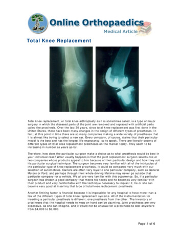
used for 6-12 months after the initial healing period, and can be used during semi-strenuousphysical activity.Figure 2 - Functional Knee BraceThe rehabilitative knee brace is used immediately after knee surgery for 1-2 months. Itrestricts nearly all movement of the knee. Typically, the patient is using crutches and any impactor load on the knee could cause re-injury.Figure 3 - Rehabilitative Knee BraceThe unloader knee brace usually requires a prescription and is used to treat kneeosteoarthritis. Its unique design forces the knee to maintain proper alignment. It also forces6
much of the normal knee load to the thigh. This aids in pain management as well as injuryprevention.Figure 4 - Unloader Knee BraceFinally, the knee sleeve is the most recognizable and easily obtained knee brace. Itprovides minimal support and alignment through compression of the knee joint. It is sold atpharmacies and sporting goods stores alike, and typically can be bought for 20- 40.Figure 5 - Knee SleeveOverall, the market for knee braces is heavily covered with the various configurationsshown. A wide variety in price and quality is observed, with high end prophylactic bracesnearing 2000. The research conducted suggests there is little room for innovation in this sectorwith regards to knee brace support design.Piezoelectric MaterialA piezoelectric material is one that exhibits an electrical response to a mechanical stress,or a mechanical response to an electrical stimulus. In plain words, when the material is underload, it produces a small electric charge; conversely, if current is passed through it, the material7
will move. They have been used in sensor applications, as well as small power sources andtimekeeping applications. Fig. XX illustrates the piezoelectric effect.Figure 6 - The piezoelectric effectPiezoelectrics can be categorized into two broad areas: ceramics and polymers. Ceramicshave rigid structures and were the first type to be used in various applications. They typicallyhave higher electrical outputs. Polymers have, until recently, been under-utilized as piezoelectricdevices. Recent improvements to their electric potential have caused them to be used more.Their flexibility gives them greater variability in application compared to ceramics.Piezoelectrics are modeled based on their configuration. The two most basicconfigurations are the cantilever beam model and the tensile model. The cantilever beam modeldictates that the piezoelectric have a fixed and free end, with a load applied perpendicular to thematerial axis. The deflection causes the electric response. Oscillatory vibration maximizes theoutput from this set up.Figure 7 - Cantilever Beam ConfigurationThe tensile load model has the material under axial load and the resultantelongation/compression causes the electrical response. This configuration produces less powerthan the cantilever beam, but has more applications in typical products.8
Figure 8 - Tensile ModelMore piezoelectric configuration models can be found in appendix A.Electro-Stimulation TechnologyElectro-stimulation therapy is a medical procedure, in which electric current is passedthrough tissue, muscle, and bone in order to provide therapeutic benefits to the patient. Thesebenefits range from general pain management, to improved joint mobility, tissue repair, andblood flow improvement. Electro-stimulation machines can be stationary units or portable kits.The current is passed through two or four electrodes placed on the skin of the patient.There are several modalities, or delivery methods, by which the current is transmitted.The most common are High Voltage Pulsed Current (HVPC), Russian, and TranscutaneousElectrical Nerve Stimulation (TENS). TENS is primarily used for pain management, and isrelatively simple compared to the other modalities. This makes it an ideal modality for thePiezoelectric Knee Brace.TENS is characterized by the following specifications:CategoryCurrentVoltagePulse DurationPulse FrequencyMinimum.10 mA10 V40 microseconds2 pulses per secondMaximum10 mA110 V250 microseconds250 pulses per secondThese criteria represent the average capabilities of portable and stationary TENS units.Typically, the units have varying levels of intensity controlled by the user. These specificationswill serve as a target benchmark for the Piezoelectric Knee Brace.Current Products and Best PracticesState of the art research uncovered three products and concepts that indicate highfeasibility for the Piezoelectric Knee Brace. They do not meet all design goals, but collectivelyshow that such a design is possible.9
The first is a product called from BioniCare. The BioniCare Knee System is a knee bracewith integrated electro-stimulation therapy, powered by an external battery pack. Essentially itacts as an unloader brace, it also requires a prescription and is used to treat knee osteoarthritis.Studies show that it may in fact be a viable alternative to knee replacement surgery. It carries ahefty cost of 2000-2500, depending on the model and specific configuration options.Figure 9 - BioniCare Knee SystemNext, a piezoelectric energy harvesting concept is being developed for militaryapplications. The device, called the Pizaccato, currently designed to be mounted to the knee,would generate electricity to power specific equipment carried by soldiers on the battlefield. Itconsists of a four piezoelectric ceramics in a cantilever beam configuration. They rotate andstrike nubs along an outer ring as the wearer walks. Current estimates put power generation inthe range of 2-30 milliwatts. Furthermore, full scale production cost estimates suggest unitsselling for between 10 and 20.Figure 10 - Piezoelectric Energy HarvesterLast is a prototype developed by Georgia Institute of Technology research students. It isessentially a polymer piezoelectric material mounted to the elbow. Modeled by the tensileloading configuration, the polymer stretches and contracts as the elbow bends. Electrical outputestimates are in the range of 2 microwatts/cc of piezoelectric material. While this seems low, theknee would provide more room to scale the design up, and well as utilization of all 360 degreessurrounding the joint.10
Figure 11 - Georgia Tech ConceptConceptual DesignsThe next part of product development is the generation of various concepts. To beconsidered, concepts need to meet the most basic design objective. The first of the five conceptsis the cantilever hub concept (CHC). The CHC uses a ceramic piezoelectric cantilever beam on afree-spinning hub. This cantilever hub is then combined with a fixed outer ring containing nubs.When said free-spinning hub oscillates as the user flexes the knee, it strikes the nubs lining thefixed outer ring. This will cause a deflection, which will then produce energy through thepiezoelectric. The energy developed will then be stored or sent back into the desired anatomy viaelectrodes. This method is hypothesized to develop a high potential for power generation.11
Figure 12 - Cantilever Hub Conceptual DrawingThe next conceptual design is the tensile concept (TC), modeled after the GeorgiaTechnical Institute research project. The TC is a series of polymer piezoelectric tensile strips thatrun parallel to the length of the leg. When the knee is fully extended, the strips are in a neutralposition. When the knee bends, a tension is developed on the exterior side of the strips. Thistension allows the polymer piezoelectric to develop energy. This energy will then be gatheredand stored or sent back into the knee anatomy via electrodes. The polymer strips could be easilyintegrated with various braces.12
Figure 13 - Tensile Conceptual DrawingThe third conceptual design is the zipper concept (ZC). The ZC uses a series of ceramicpiezoelectric cantilever beams to harvest energy. The configuration is set such that a fixedexterior sheath is attached to the posterior tibial part of the lower leg. The cantilevers arearranged on the inside the sheath facing each other in pairs. A series of agitators is then set on amobile rod inside the sheath. The mobile rod oscillates with the extension and contraction of theknee. While oscillating, the agitators strike the cantilever beams inside the fixed sheath. Thesestrikes from the agitator allow the cantilevers to develop energy that is either stored or releasedback into the knee via electrodes.13
Figure 14 - Zipper Conceptual DrawingThe fourth concept is the gear crank concept. This concept utilizes the mechanicaladvantage of a gear train to increase the frequency of oscillations of the piezoelectric materialduring each step. In the gear crank concept, a driving gear is fixed to the axis of rotation of theknee. The driving gear drives a smaller gear which shares a shaft with an “agitation gear”. Theagitation gear rotates in at the same speed as the driven gear and has a series of prongs extendingout of it. Surrounding the agitation gear is series of piezoelectric cantilever strips. As theagitation gear spins, it strikes the piezoelectric cantilevers and thus generates energy from themechanical movement.14
Figure 15 - Gear Crank Concept ModelThe fifth concept is the impact concept. The impact concept has a series of piezoelectricdistally weighted cantilever beams attached to the knee brace. When the user takes a step, theimpact of the step is absorbed and amplified by the distal weights and the energy is harvestedthrough the piezoelectric cantilevers. The energy is then stored in a battery and then transferredto the electrodes in TENS pulses.15
Figure 16 - Impact Concept DesignConcept Evaluation and ComparisonThe five conceptual designs have different benefits and drawbacks. The first step inanalyzing the concepts was a general concept screening. Various criteria were developed basedon the product requirements. The goal was to determine which concepts to proceed with byeliminating those concepts deemed not worthy of continued development. The result of this16
initial screening eliminated the tensile concept due to its low potential to meet the energygeneration requirement. The cantilever hub concept was also removed from consideration, as thegear crank concept is similar, and superior, concept.With the field narrowed, a more in depth analysis was needed to select the final concept.This required more quantifiable criteria, based on the requirements. Relative weights wereassigned to each criterion based on customer needs and input. A table showing the criteria,weights, and baseline requirements and design goals is shown below.Figure 17 - Criteria and RequirementsThis table was the basis for scoring the remaining three concepts. Each concept received a scorebetween one and three for each criterion. The score was based on a direct comparison of theconcepts with each other. The results of this analysis are shown in the concept scoring matrixbelow.17
Figure 18 - Concept Scoring MatrixBased on the scoring, the Gear Crank concept was selected for continued development.This was mainly due to the high weight assigned to the energy generation criterion. If there isnot enough power produced, then the product will not fulfill its most basic and crucialrequirements.Plan of Technical AnalysisOur project is highly dependent on several technical aspects. These aspects will beconsidered, tested, and analyzed to determine the final development of our designs. It isimportant to determine the parameters of each technical aspect, as well as an analytical model foranalysis, finally resulting in a physical model to test and verify results. The following four highlevel objectives were created to show the focus on the technical analysis: determining anoptimum piezoelectric configuration, designing the energy storage system, designing an electrostimulation delivery circuit, and integrating the energy mechanism into a knee brace.The first priority of technical analysis is to determine the optimum piezoelectricconfiguration. The main considerations will be the piezoelectric material, configuration andloading conditions, and ratio of kinetic movement to electricity produced. Ceramics are better fora rigid structure while a polymer would better suit a flexible design. Cantilever and tensileloading conditions will also be explored. Following the conceptual configuration, an analyticalmodel will be derived through equations relating human movement and electricity generation.Once derived, these equations will be optimized to develop the most energy from humangenerated kinetic movement. Eventually, a physical model will be developed that can simulaterepetitive movement constrained by the range of motion from a human knee. Appendix Bcontains various measurements of range of motion associated with different physical activities.This will give validity to the results of the analytical model.After energy conversion, the piezoelectric knee brace will need to store the capturedenergy. The first piece will be to determine the storage parameters. These will largely depend onthe configuration selected, but also include basic electrical circuit component parameters.Ideally, an analytical model will be developed that can predict energy losses of various storagesystems based on the highlighted parameters. Again, the final step will be to validate the modelwith a physical test. This requires that the energy storage circuit be fabricated and tested in thelab.18
The electro-stimulation delivery circuit is the second priority in technical analysis, afterthe harvesting configuration. The primary design parameters will be constrained by the TENSspecifications to comply with FDA requirements. Significant research of electrical controlcomponents will need to be conducted to deliver the electricity according to these TENSspecifications. An analytical model consisting mainly of a circuit diagram and expected outputswill be developed. Once complete, the physical circuit will be fabricated and testing in the lab.Finally, consideration needs to be given throughout with respect to integrating the energymechanism with the knee brace. This will be affected primarily by the piezoelectricconfiguration. The ideal design situation is a mechanism that can work with any of the varioustypes of knee braces, however, specific consideration will be given to the functional knee braceand the knee sleeve, as these are the most common braces.Technical AnalysisThe first step in our technical analysis was to determine the most effective configurationof piezoelectric strips for maximum energy harvesting. The TENS electro stimulation therapymodality selected requires delivery of 20V and 5mA. Assumptions for the scenario with thehighest demand were made: TENS delivery circuit is run for 60 minutesUser is walking constantly for 60 minutesUser is walking with an ideal human gaitTorque developed in knee from each step was 40NmNo losses through circuitryRunning the device for 60 minutes while delivering 5mA at 20V requires 360 joules.The goal is to determine the configuration needed to meet the requirements of this mostdemanding scenario. There were several design variables that would affect the energy harvested,the main ones being: physical configuration and number of piezoelectric strips, size ofpiezoelectric strips, force applied to the piezoelectric, and frequency of piezoelectric oscillations.These represent the essential factors to determine.The COMSOL multi-physics MEMS software module was used to analyze apiezoelectric in the cantilever configuration. The cantilever was modeled with one end fixed anda load applied to the distal free end. The piezoelectric material chosen was lead zirconiumtitanate (PZT-5H also known as NAVY Type VI) since it is both readily available and a ceramicpiezoelectric, thus has a higher power potential. Polyetheretherketone (PEEK) material waschosen to model the linear elastic properties of a cantilever beam in the specified configuration.PEEK was chosen due to its lack of distortion the intended properties of the model. Thecantilever was placed in a d33 configuration, the most effective energy harvesting configurationfor cantilever beams. By determining the magnitude of the force applied to the PZT, the modelwill output the electric potential generated by the beam. This data is then used in calculationsdetermining the maximum energy generation of the gear crank concept. The design would be aniterative process, as the force applied to each strip would change with the number of strips.With the torque produced at the knee during each step known, the force applied to eachpiezoelectric strip could be determined. Utilizing data from a study published in the Journal of19
Rehabilitation Research and Design, the average maximum torque generated by the knee wasdetermined to be about 40 Nm (Martinez). The data represented normal walking on level-groundat an average speed of 1.31 m/s. The data was then used to represent the maximum possibletorque that could be applied to the device while walking. The torque was assumed to begenerated about the knee’s center of rotation. Thus, the group chose a gear size of 0.05m indiameter to rotate about the same axis to determine the amount of torque the gear can generate.At a radial distance of 0.025m from the axis of rotation (tip of the driver gear), the potentialtorque is 1 Nm. The group chose a gear ratio of 2:1 to increase the angle of rotation of the drivengear so that the piezoelectric beams could be actuated more frequently. The calculated torque ofthe driven gear is 0.5 Nm. To find the deflection and thus output of the piezoelectric beams, thetangential force of the Plucker gear (fixed to the driven gear and thus has the same gearration/speed) was calculated to be 40 N.This 40 N tangential force will be applied to each of the piezoelectric beams. The groupchose to use 10 beams to apply a 4 N force per beam to reduce the amount of force and preventfailure of the piezoelectric beams. Using the previously mentioned COMSOL Multi-physicsMEMS model developed, the 4 N load was applied to the piezoelectric beams to determine theoutput. The maximum voltage output reading from the COMSOL model was 120 V.Based on the limited research and applicable mathematical models for determining exactpiezoelectric current outputs, experimental results are much more reliable. The Pizaccatoconcept, explained in the state of the art review, is a similar loading condition with applicableexperimental results. Therefore, it was compared with the loading conditions of the gear crankdesign. To determine the amount of energy the device needs to generate to meet therequirements, the most demanding scenario was considered, as outlined above. In Figure 19, theupper table represents a list of possible voltage and current outputs that were considered,however, to maintain a reasonably conservative stimulation to the end user of the product, theteam chose 20 V and 5 mA as our maximum. This ensures the output will not the threshold ofdanger which occurs at about 10 mA. At 20 V and 5 mA, the energy usage over an hour wouldbe 360 J. Through comparison to the energy production from the Pizaccato design (8.136 J overan hour), the calculated multiplication factor specify that 44x the output of the Pizaccato kneebrace was needed to obtain the required energy generation. The gear crank concept’s inherentfeatures provide enhancements over the Pizaccato design. In order to reach the 44x output of thePizaccato concept, several multiplication factors were identified within the design. First was agear ratio of 2:1, followed by 2.5x more piezoelectric strips, and 8x higher maximum voltageoutput. This technical analysis allowed the group to determine the designs necessary for thedesired energy generation of 360 J. By comparison, our concept is within 1.1x the amount ofenergy needed to be generated in the worst case scenario.20
Figure 19 - Calculation SpreadsheetNow that the energy harvesting configuration is complete, the next step is to determinethe energy storage system. This consists of the required circuitry and storage device for theelectricity. This required considerable research. The most important considerations were todetermine the specific device that would store the energy, and subsequently the requirements forcharging such a device. The group consulted with Prof. Fisher of the Mechanical EngineeringDepartment and with Prof. McNair of the Electrical En
The first is a product called from BioniCare. The BioniCare Knee System is a knee brace with integrated electro-stimulation therapy, powered by an external battery pack. Essentially it acts as an unloader brace, it also requires a prescription and is used to treat knee osteoarthritis.