Transcription
3/13/2011DR & CR: TECHNIQUESAND STRATEGIESEVERYONE CAN USEWCEC 2011Dennis Bowman RT(R)Clinical InstructorCommunity Hospital of the Monterey Peninsula (CHOMP)Cabrillo CollegeAll of our technique experiments finally beganafter we received 4 of these 5 phantoms.Our digital world has a new paradigm In the film/screen world, when a film was light therewas nothing you could do to fix it. Hence, the motto was: “when it doubt, dark it out.” This meant whenever you weren’t sure about atechnique, you would always opt for the dark side(which is why the hot light was so handy). That concept should be completely different in thedigital world. The new digital paradigm is all aboutgetting a great image using the least amount ofradiation possible. The other paradigm shift has to do with higher kVp’s.DosimeterPlus the150 cc Ion chamberkVp MeterStuart Bushong and the penguin1
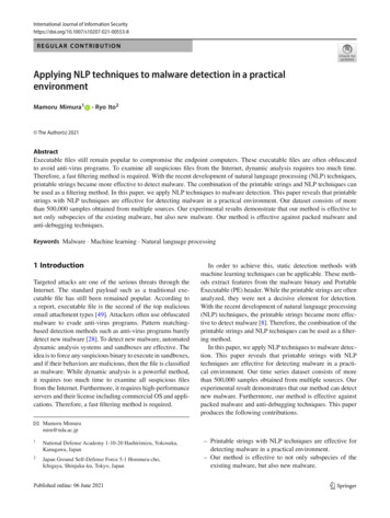
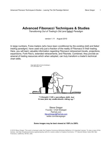
3/13/2011Low Flier Out of over 175 slides I have, 15 Low Flier’s.Thinking outside the box,especially when it’s a brand new box. CT first used in 1972. Fuji’s first CR out in 1983. The kVp on a foot CT is 120 kVp. And it’s contrasty andbeautiful. Of course it is extremelywell collimated, which is whywe can’t use such a high kVp. On the other hand Barry Burns –the CR guru Barry Burns - MS, RT(R), DABR – AdjunctProfessor of Radiologic Science, Universityof North Carolina School of Medicine inChapel Hill, North Carolina, stipulates thatwhen using CR everyone can increase 1520 kVp from film/screen techniques.CR50 kVThe following slides show a hand andshoulder phantom exposed from 50 to100 kV to demonstrate the minutedifferences visualized on an image usinghigher kV’s with both CR and DR.CR60 kV2
3/13/2011CR70 kVCR80 kVCR90 kVCR100 kVDR50 kVDR60 kV3
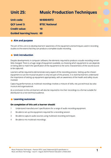
3/13/2011DR70 kVDR80 kVDR90 kVDR100 kVCR50 kVCR60 kV4
3/13/2011CR70 kVCR80 kVCR90 kVCR100 kVDR50 kVDR60 kV5
3/13/2011DR70 kVDR80 kVDR90 kVDR100 kVThese are the “new” digital Optimum kVp’sas developed by Barry BurnsDIGITAL OPTIMUM kVpUniversal CR Technique Chartusing a standard 2.1 LgMUNIVERSAL CR TECHNIQUE CHART LgM 2.1PartBody Part - AdultChest (Bucky/Grid)Chest (Non-Grid)AbdomenExtremities (Non-Grid)Extremities (Grid)Extremities (Bucky)AP SpinesC-Spine LateralT-Spine LateralL-Spine LateralRibsSkullBE (Air Con)Abdomen (Iodine)Pediatric:Infant ExtremitiesPediatric Chest 80AbdomenAP (Grid)AnkleAPAnkleOblAnkleLatChest -AdultAP (400 - tt -72")Chest -AdultLat (400 - tt - 72")Chest - ChildPA (400 - 72")Chest - ChildLat (400 - 72")Chest - InfantAP (400 - 40")Chest - InfantLat ( 400 - 40")C-SpineAP (Bucky - 72")C-SpineAP (Bucky - 40")C-SpineOdontoid (72")C-SpineOdontoid (40")C-SpineLat (Bucky - 72")C-SpineSwimmers (40")C-SpineTrauma Obl. (50"-tt)C-SpineAP (100 - 40")C-SpineLat (100 -72")ElbowAPElbowOblElbowLatFemur - DistalLateral (400 - tt)FingerAll Views - (100)FootAPFootOblFootLatForearmAP (100)ForearmLat 3737070666610 -151.81.61.52 - 2.54.5 - 5.5241212.5516612.5 - 1540 - 666620 - 2521.81.63.2 - 47.5 - 92.5512156.418 - 20815 - 2050 - 8858585858510077777770707077637070707070666630 - 402.52.225 - 6.412.5 - 153.26.41218 - 208 - 10251020 - 2550 - 752011 - 12352.83.22.851.252.83.23.53.53.522.56
3/13/2011Size of the Patient – The techniquesare of a small, medium and large male Small 120-160 lbs. Medium 160-200 lbs. Large 200-240 lbs. Females would be approximately 10 lbs. lighter.Page 2 of the LgM 2.1Universal CR Technique ChartUNIVERSAL CR TECHNIQUE SpineT-SpineWristWristWristViewAP - (400 - tt)X-Table Lat (Grid)AP (100)AP (Bucky)Obl (Bucky)Lat (Bucky)Sunrise (100 - tt)X-Table Lat (400 - tt)APX-Table Lat (Grid)Obl (100 - 40")AP (Grid)Upper (72")Lower (40")Obl (72")AP (100)Mercedes (100)Axillary (100)CaldwellWatersLateralAPLat (Grid)AP (100)Lat (100)All ViewsAPLat (2 sec)PAOblLatZygomatic Arch SMV view (100 - 30")If you have never seenthese kind of techniques before They are definitely going to be a bit on thescary side. Any radiographer who really knows theirfilm/screen (or low kV digital) techniqueswill hardly be able to believe that they arepossible.SmallLgM 78580858077777785858585857777639090666670330 - 5033.53.23.242.58 - 1280 - 10010108 - 1210 - 1510 - 204.5126810412532.51.257.5 - 1015 - 585857777639090666670460 - 8053.53.23.253.616 - 20125 - 16012.52014 - 2020 - 2520 - 306-716 - 208101251563.5 - 43.21.25 - 1.516 - 2035 - 5858577776390906666706-4100 - 120743.53.564.525 - 30200 - 320163025 - 3030 - 4030 - 409 - 1025 - 3010121461874.541.5 - 23060 - 7022.22.5702702.5703So what does kVp and mAs do? Not what it did in the film world, that’s for sure!! Obviously there is still an optimum kVp, but itnow controls only subject contrast. To a large extent, mAs does not really controldensity/brightness any more. Density and brightness are now mainly controlled byprocessing algorithms. You just need enough mAs or your image willhave quantum noise (pixel starvation, mottle).Quantum mottle or noiseWhat does optimum kVp mean? Optimum means the best!! Even though it’s digital, you still have to stay inHorribleBadPerfectOver Saturated(Permanent Lossof Contrast)the optimum range, you can’t start using 120 kVpon everything. If you do use too much kVp it will penetrateright through your patient and hit the plate ordetector because of incorrect attenuation. This will cause the image to be over penetrated,(saturated) causing a permanent loss in contrast.7
3/13/2011Differences Between Digital And Film Centering and collimation are very importantwhether it’s table top or bucky work. Dose Exposure Index/Indicator (DEI) numbers(S, LgM, EI, ReX, EXI, DEI) are how you tell ifyour technique was correct.Centering and the Dose Exposure NumbersMore Differences Between Digital And Film The concept of Agfa’s 2.0-2.3 LgM range, Fuji’s400-100 (150-75) S range, GE’s (DR) 2-6 rangeand Siemens‘ 200-900 range. Even with the range you should always beshooting for the “best” number in that range(which means the lowest dose). Lead shields and metal in the body can alsodramatically affect the DEI number. These DEI numbers are easily corrupted orskewed (but only up to 75% in most cases).Agfa CR Perfectly centered and collimated to 14x14117 kVp @ 5 mAs –S# is 187 The following slides show the chest, elbow andshoulder phantoms and how a change incentering and or collimation can affect thedose exposure number.Perfectly centered - now 17x14 - 117 kVp @ 5 mAsS# is 16323.3% changeCentered 1” high –117 kVp @ 5 mAsS# is 13056.7% change8
3/13/2011Centered 2” high – 117 kVp @ 5 mAsS# is 12066.7% changeNow centered 1” low – 117 kVp @ 5 mAsS# is 16323.3% changePerfect centering – 4 sided collimationLgM 1.81Kitty Corner – touching at both cornersLgM 1.810% changeLong side touching edgeLgM 1.8513.3% changeCentered – top side touchingLgM 1.8513.3% change9
3/13/2011Off to one side – no collimation touching sidesLgM .737-91.1% changeNo collimation - please note contrastLgM 1.9446.7% changeSiemens DR built in detectorPerfect Centering – 4 sided collimation70 kVp @ 1.1 mAs EXI 551Top and side touchingLgM .868-88.3% changeCompare the contrast and brightness of themiddle and right images compared to theperfect one on the left. This is an exampleof permanent loss of contrastOff center to left side but not touching side70 kVp @ 1.1 mAsEXI 5774.7% change10
3/13/2011Off center to left and is touching side70 kVp @ 1.1 mAsEXI 5744.2% changeTouching the bottom70 kVp @ 1.1 mAsEXI 5723.8% changeKitty corner – not touching any sides70 kVp @ 1.1 mAsEXI 63915.9% changeTouching bottom and left side70 kVp @ 1.1 mAsEXI 526-9.1% changeShoulder phantom with 3 sheets ofPolyethylene to make it the thickness of alarge adult male.These experiments will show the differencein EXI numbers when the collimation is leftmore and more open.GE built in detector (DEI range .42 -1.27)8”x8”DEI .600.0% change11
3/13/20119”x9”GE built in detectorDEI .6610.0% change11”x11”GE built in detectorDEI .8033.3% changeGE built in detector13”x13”DEI .9660.0 % change10”x10”12”x12”GE built in detectorDEI .7118.3% changeGE built in detectorDEI .8948.3 % changeMultiple exposures on one CR plateHere is a 2 on 1 calcaneus. You can see that thelateral had a better technique used. Only onealgorithm and Look Up Table is used for bothimages. Almost always more than 1 exposure ona plate will cause a corrupted DE number.12
3/13/2011To summarize the previous 27corrupted dose exposure number slides.How different is DR? With all the examples, the technique alwaysstayed the same. It was just the centering orcollimation changes that corrupted the DEnumber. Even though the dose exposure number (EXI,S, LgM, DEI) has been corrupted up to 75%, theimage is still perfectly passable in any facility.Direct Radiography It’s like taking a picture on your digital camera. It is now WAY TOO EASY to repeat an image!!! Techs haveforgottenthat anyexposuremay causetissue or celldamageto theirpatient.The Ferlic Filter Typical hard to get, thick cm. shots likeSwimmers, x-table lateral lumbar, x-tablelateral hip are noticeably uglier. The Ferlic Filter is definitely needed.13
3/13/2011Here are 4 different Ferlic Filters.Swimmers and x-table hip, Lateral C-spine,X- table lateral L-spine and AP T-spinesDown while positioning the tube for the LateralC-spine (x-table or standing)Then just slip it up to shoot.It stays in place with a magnet.14
3/13/2011“Sliders” bags. Comes in 2 sizes.One for DR detector and grid,the other for CR cassette and grid.Anchor-leg stabilizerDigital short axis grids for CRDecubitus (short axis) gridsshould be used on non bucky chestsbigger than 25cm with both CR and DRRegularDecubitus We found the perfect chest grid to be: 178 LPI 6:1 grid ratio 48”-72” focus Carestream and Konica use 104 LPI because oftheir grid suppression software. We increase our technique 25 kVp and 1 step inmAs. We also picked a four sided grid where thecassette falls into it as apposed to a 3 sided gridwhere you slide the cassette in.Non grid exposure with the digital portable.15
3/13/2011Same patient the next day using the grid.Problems with critiquing digital images It is impossibleto prove you used the idealtechnique if all you are using is the finishedimage contrast and density as a gauge. The DEI numbers are very dependable as long asyour positioning, collimation and exposurefactors are very good. Some DR control panels have no DEI indicator.Ways to Critique a Digital (DR or CR) Image You definitely need to use the magnificationmode to check for noise.Witness the awesome power ofAutomatic Rescaling You should always be able to Level andWindow and make your image look wellpenetrated and contrasty. This won’t necessarily prove you didn’toverexpose the patient, but it will confirmthat it is a passable image.In the film world thisis how much darker(or in other wordshow much moreradiation the patientis getting) when youincrease the mAs.Fuji85 kVp @ 4 mAs - S# 35716
3/13/201185 kVp @ 8 mAs - S# 17185 kVp @ 32 mAs - S# 3885 kVp @ 200 mAs - S# 685 kVp @ 400 mAs - S# 385 kVp @ 500 mAs - S# 44 mAs32 mAs200 mAs500 mAs17
3/13/2011Agfa85 kVp @ 4 mAs LgM 2.1185 kVp @ 8 mAs LgM 2.4085 kVp @ 16 mAs LgM 2.7085 kVp @ 32 mAs LgM 2.9685 kVp @ 40 mAs LgM 2.994 mAs16 mAs32 mAs40 mAs18
3/13/2011GE built in detector (.36 – 1.07)85 kv @ 2 mAsDEI .9685 kv @ 8 mAs85 kv @ 32 mAsDEI 4.0DEI 14.6785 kv @ 4 mAsDEI 1.9785 kv @ 16 mAsDEI 7.7285 kv @ 64 mAs DEI 27.4119
3/13/2011mAs Dose Creep (Creeping Dose/mAs) National problem. The unfortunate ability for a radiographer to usefar too much mAs and have the computer “fix”the problem and give a very readable image. Over time techs slowly start using more andmore mAs. Some hospitals can be 10 generations deep fromusing film/screen.To use a universal chart,what needs to be done? Make sure all the tubes are shooting the same. All of your control panels will need to be set withthe new kVp’s. The readers are all giving the same DEI number. Agfa might need the MUSI Contrast in the MUSICAfactory setting changed in the reader to do this. Fuji and others may change the GT (Look Up Tabletype) and GA (slope of Look Up Table). Is the DEI range given by thevendor perfect for your facility?How can there be aUniversal CR/DR technique chart? As we all well know, this would have beenimpossible in the film/screen processor days. All modern generators (23 years or newer) arehigh frequency, so if the tubes are in calibrationthey should all be shooting the same. Since the CR/DR manufacturers set their systemsup to have the perfect Dose Exposure Indicator #appear when .7 mR hits the plate, then any giventechnique will work with all the vendors if the xray tubes are all shooting the same.How did your vendorset up your QC viewer? We were told from day 1 that we would not needto change our techniques at all. This way we would only be learning computerwork, not new techniques. We weren’t given the choice to do the 15% Rule(or told that it was even possible). They set the image up to look like film (soft)instead of more digital (like DR). It wasn’t until we had DR for about 2 years thatwe even realized what digital images should reallylook like.Here is a nicely shot PA chest using the AEC. TheLgM is a 1.81 and there is absolutely no mottle. We (my colleague Ramiro Villanueva and I)believ
Universal CR Technique Chart Part View kV mAs kV mAs kV mAs Hip AP - (400 - tt) 77 3 77 4 77 6 - 4 Hip X-Table Lat (Grid) 90 30 - 50 90 60 - 80 90 100 - 120 Humerus AP (100) 70 3 70 5 70 7 Knee AP (Bucky) 81 3.5 85 3.5 85 4 Knee Obl (Bucky) 81 3.2 85 3.2 85 3.5 Knee Lat (Bucky) 81 3.2 85 3.2 85 3.5 Knee Sunrise (100 - tt) 70 4 70 5 70 6 Knee X-Table Lat (400 - tt) 70 2.5 70 3.6 70 4.5 L-Spine .