Transcription
ER & EER to RelationalMappingChapter 91
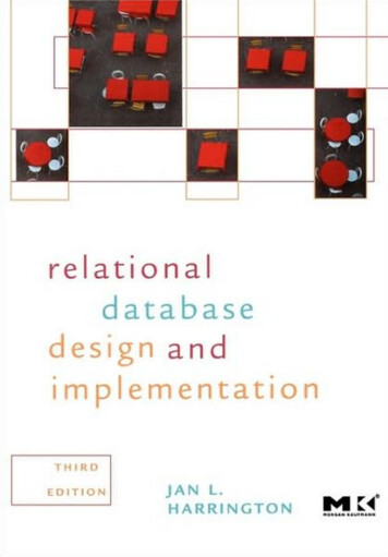
Figure 3.2FnameMinitERschema diagram for the company database.LnameNumberAddressNameSex1NWORKS pervisorsuperviseeNWORKS S OFNDEPENDENTNameSexBirthDateRelationship Addison Wesley Longman, Inc. 2000, Elmasri/Navathe, Fundamentals of Database Systems, Third Edition
Step 1: For each regular entity type E Create a relation R that includes all thesimple attributes of E. Include all the simple component attributesof composite attributes. Choose one of the key attributes of E asprimary key for R. If the chosen key of E is composite, the setof simple attributes that form it will togetherform the primary key of R.Chapter 92
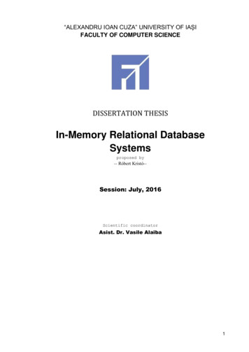
Figure 7.5 Schema diagram for the COMPANY relationaldatabase schema; the primary keys are RTDATEDEPT IONDNUMWORKS ONESSNPNOHOURSDEPENDENTESSNDEPENDENT NAMESEXBDATERELATIONSHIP Addison Wesley Longman, Inc. 2000, Elmasri/Navathe, Fundamentals of Database Systems, Third EditionDNO
Step 2: For each weak entity type W withowner entity type E Create a relation R, and include all simpleattributes and simple components ofcomposite attributes of W as attributes of R. In addition, include as foreign key attributesof R the primary key attribute(s) of therelation(s) that correspond to the ownerentity type(s).Chapter 93
Figure 7.5 Schema diagram for the COMPANY relationaldatabase schema; the primary keys are RTDATEDEPT IONDNUMWORKS ONESSNPNOHOURSDEPENDENTESSNDEPENDENT NAMESEXBDATERELATIONSHIP Addison Wesley Longman, Inc. 2000, Elmasri/Navathe, Fundamentals of Database Systems, Third EditionDNO
Step 3: For each binary 1:1 relationshiptype R Identify the relations S and T that correspond tothe entity types participating in R. Choose one ofthe relations, say S, and include as foreign key inS the primary key of T. It is better to choose an entity type with totalparticipation in R in the role of S. Include the simple attributes of the 1:1relationship type R as attributes of S. If both participations are total, we may merge thetwo entity types and the relationship into a singlerelation.Chapter 94
Figure 7.5 Schema diagram for the COMPANY relationaldatabase schema; the primary keys are RTDATEDEPT IONDNUMWORKS ONESSNPNOHOURSDEPENDENTESSNDEPENDENT NAMESEXBDATERELATIONSHIP Addison Wesley Longman, Inc. 2000, Elmasri/Navathe, Fundamentals of Database Systems, Third EditionDNO
Step 4: For each regular binary 1:Nrelationship type R Identify the relation S that represents theparticipating entity type at the N-side of therelationship type. Include as foreign key in S the primary keyof the relations T that represents the otherentity type participating in R. Include any simple attributes of the 1:Nrelationship type as attributes of S.Chapter 95
Figure 7.5 Schema diagram for the COMPANY relationaldatabase schema; the primary keys are RTDATEDEPT IONDNUMWORKS ONESSNPNOHOURSDEPENDENTESSNDEPENDENT NAMESEXBDATERELATIONSHIP Addison Wesley Longman, Inc. 2000, Elmasri/Navathe, Fundamentals of Database Systems, Third EditionDNO
Step 5: For each binary M:N relationshiptype R Create a new relation S to represent R. Include as foreign key attributes in S theprimary keys of the relations that representthe participating entity types; theircombination will form the primary key of S. Also, include any simple attributes of theM:N relationship type as attributes of S.Chapter 96
Figure 7.5 Schema diagram for the COMPANY relationaldatabase schema; the primary keys are RTDATEDEPT IONDNUMWORKS ONESSNPNOHOURSDEPENDENTESSNDEPENDENT NAMESEXBDATERELATIONSHIP Addison Wesley Longman, Inc. 2000, Elmasri/Navathe, Fundamentals of Database Systems, Third EditionDNO
Step 6: For each multi-valued attribute A Create a new relation R that includes anattribute corresponding to A plus theprimary key attribute K (as a foreign key inR) of the relation that represents the entitytype or relationship type that has A as anattribute. The primary key of R is the combination ofA and K. If a multi-valued attribute iscomposite, we include its components.Chapter 97
Figure 7.5 Schema diagram for the COMPANY relationaldatabase schema; the primary keys are RTDATEDEPT IONDNUMWORKS ONESSNPNOHOURSDEPENDENTESSNDEPENDENT NAMESEXBDATERELATIONSHIP Addison Wesley Longman, Inc. 2000, Elmasri/Navathe, Fundamentals of Database Systems, Third EditionDNO
Step 7: For each n-ary relationship type R,n 2 Create a new relation S to represent R. Include as foreign key attributes in the S theprimary keys of the relations that representthe participating entity types. Also include any simple attributes of the nary relationship types as attributes of S. The primary key for S is usually acombination of all the foreign keys thatreference the relations representing theparticipating entity types.Chapter 98
TERNARY RELATIONSHIPS
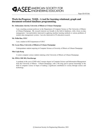
Figure 9.1Mapping the n-ary relationship type SUPPLYfrom Figure LYSNAMEPROJNAMEPARTNOQUANTITY Addison Wesley Longman, Inc. 2000, Elmasri/Navathe, Fundamentals of Database Systems, Third Edition
However, if the participation constraint(min,max) of one of the entity types Eparticipating in the R has max 1, then theprimary key of S can be the single foreignkey attribute that references the relation E’corresponding to E This is because , in this case, each entity ein E will participate in at most onerelationship instance of R and hence canuniquely identify that relationship instance.Chapter 99
Step 8: To convert each super-class/subclass relationship into a relational schemayou must use one of the four optionsavailable.Let C be the super-class, K its primary keyand A1, A2, , An its remaining attributesand let S1, S2, , Sm be the sub-classes.Chapter 910
Option 8A (multiple relation option): Create a relation L for C with attributesAttrs(L) {K, A1, A2, , An} and PK(L) K. Create a relation Li for each subclass Si, 1 i m, withthe attributesATTRS(Li) {K} U {attributes of Si} andPK(Li) K. This option works for any constraints: disjoint oroverlapping; total or partial.Chapter 911
Option 8B (multiple relation option): Create a relation Li for each subclass Si,1 i m, withATTRS(Li) {attributes of Si} U {K, A1, A2, , An}PK(Li) K This option works well only for disjoint and totalconstraints. If not disjoint, redundant values for inherited attributes. If not total, entity not belonging to any sub-class is lost.Chapter 912
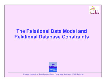
Figure 9.2Options for mapping specializations (or generalizations) to relations.(a) Mapping the EER schema of Figure 4.4 to relations by using Option A. (b) Mapping the EERschema of Figure 4.3(b) into relations by using Option B. (c) Mapping the EER schema ofFigure 4.4 by using Option C, with JobType playing the role of type attribute. (d) Mapping the EERschema of Figure 4.5 by using Option D, with two Boolean type fields Mflag and teBatchNoPFlagSupplierName Addison Wesley Longman, Inc. 2000, Elmasri/Navathe, Fundamentals of Database Systems, Third EditionListPrice
Figure 9.2Options for mapping specializations (or generalizations) to relations.(a) Mapping the EER schema of Figure 4.4 to relations by using Option A. (b) Mapping the EERschema of Figure 4.3(b) into relations by using Option B. (c) Mapping the EER schema ofFigure 4.4 by using Option C, with JobType playing the role of type attribute. (d) Mapping the EERschema of Figure 4.5 by using Option D, with two Boolean type fields Mflag and teBatchNoPFlagSupplierName Addison Wesley Longman, Inc. 2000, Elmasri/Navathe, Fundamentals of Database Systems, Third EditionListPrice
Option 8c (Single Relation Option) Create a single relation L with attributesAttrs(L) {K, A1, , An} U{attributes of S1} U U{attributes of Sm} U {T}and PK(L) K This option is for specialization whose subclasses areDISJOINT, and T is a type attribute that indicates thesubclass to which each tuple belongs, if any. This optionmay generate a large number of null values. Not recommended if many specific attributes are definedin subclasses (will result in many null values!)Chapter 913
Figure 9.2Options for mapping specializations (or generalizations) to relations.(a) Mapping the EER schema of Figure 4.4 to relations by using Option A. (b) Mapping the EERschema of Figure 4.3(b) into relations by using Option B. (c) Mapping the EER schema ofFigure 4.4 by using Option C, with JobType playing the role of type attribute. (d) Mapping the EERschema of Figure 4.5 by using Option D, with two Boolean type fields Mflag and teBatchNoPFlagSupplierName Addison Wesley Longman, Inc. 2000, Elmasri/Navathe, Fundamentals of Database Systems, Third EditionListPrice
Option 8d (Single Relation Option) Create a single relation schema L with attributesAttrs(L) {K, A1, , An} U{attributes of S1} U U{attributes of Sm} U {T1, , Tn}and PK(L) K This option is for specialization whose subclasses areoverlapping, and each Ti, 1 i m, is a Boolean attributeindicating whether a tuple belongs to subclass Si. This option could be used for disjoint subclasses too.Chapter 914
Figure 9.2Options for mapping specializations (or generalizations) to relations.(a) Mapping the EER schema of Figure 4.4 to relations by using Option A. (b) Mapping the EERschema of Figure 4.3(b) into relations by using Option B. (c) Mapping the EER schema ofFigure 4.4 by using Option C, with JobType playing the role of type attribute. (d) Mapping the EERschema of Figure 4.5 by using Option D, with two Boolean type fields Mflag and teBatchNoPFlagSupplierName Addison Wesley Longman, Inc. 2000, Elmasri/Navathe, Fundamentals of Database Systems, Third EditionListPrice
Figure 9.3Mapping the EER specialization lattice shown in Figure 4.7using multiple meRAFlagTAFlagProjectALUMNUS agUndergradFlagDegreeProgramClassStudAssistFlag Addison Wesley Longman, Inc. 2000, Elmasri/Navathe, Fundamentals of Database Systems, Third EditionCourse
Option 8A for PERSON/{EMPLOYEE,ALUMNUS,STUDENT}Option 8C for EMPLOYEE/{STAFF,FACULTY,STUDENT ASSISTANT}Option 8D for STUDENT ASSISTANT/{RESEARCH ASSISTANT,TEACHING ASSISTANT} STUDENT/{STUDENT ASSISTANT} STUDENT/{GRADUATE ASSISTANT,UNDERGRADUATE STUDENT}
schema of Figure 4.3(b) into relations by using Option B. (c) Mapping the . EER. schema of Figure 4.4 by using Option C, with JobType playing the role of type attribute. (d) Mapping the . EER. schema of Figure 4.5 by using Option D, with two Boolean type fields Mflag and Pflag. (a) Mapping the EER schema of Figure 4.4 to relations by using .