Transcription
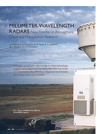
LocAP: Autonomous Millimeter Accurate Mapping of WiFi InfrastructureRoshan Ayyalasomayajula, Aditya Arun, Chenfeng Wu, Shrivatsan Rajagopalan,Shreya Ganesaraman, Aravind Seetharaman, Ish Kumar Jain, and Dinesh Bharadia(roshana, aarun, chw357, s1rajago, sganesar, arseetha, ikjain, dineshb)@ucsd.eduUniversity of California, San DiegoAbstractLocAP DeployedIndoor localization has been studied for nearly two decadesfueled by wide interest in indoor navigation, achieving thenecessary decimeter-level accuracy. However, there are noreal-world deployments of WiFi-based user localization algorithms, primarily because these algorithms are infrastructuredependent and therefore assume the location of the accesspoints, their antenna geometries, and deployment orientationsin the physical map. In the real world, such detailed knowledge of the location attributes of the access Point is seldomavailable, thereby making WiFi localization hard to deploy. Inthis paper, for the first time, we establish the accuracy requirements for the location attributes of access points to achievedecimeter level user localization accuracy. Surprisingly, theserequirements for antenna geometries and deployment orientation are very stringent, requiring millimeter level and sub-10 of accuracy respectively, which is hard to achieve with manualeffort. To ease the deployment of real-world WiFi localization, we present LocAP, which is an autonomous system tophysically map the environment and accurately locate theattributes of existing wireless infrastructure in the physicalspace down to the required stringent accuracy of 3 mm antenna separation and 3o deployment orientation median errors,whereas state-of-the-art algorithm reports 150 mm and 25orespectively.1IntroductionIndoor navigation requires precise indoor maps and accurateuser location in these maps. Google, Bing, Apple or OpenStreet Maps have made considerable progress towards providing precise indoor maps for notable locations like airportsand shopping malls [1–4]. On the other hand, there are twodecades of research on indoor localization using WiFi infrastructure that achieve decimeter accurate user locations[22, 30, 37, 39, 50, 51, 53, 58, 59, 65–69]. Despite these innovations, we still cannot use our smartphones to navigate inthese indoor environments.The key reason for this inability is the absence of the bridgeUSENIX AssociationAP1After LocAPAP2AP1𝜃1𝜃2AP2userAP3Unknown AP𝜃3AP3Predicted APFigure 1: Implementation of LocAP: (Left) An unknownenvironment with unknown AP attributes where LocAP isdeployed. (Right) LocAP once deployed determines the APattributes in the physical map enabling triangulation baseduser localization.providing the context of the physical map to the user locations.While there is recent work [8] that bridges this gap, it, likeother state-of-the-art localization algorithms [37, 59, 66], isdependant on the accurate location attributes of the WiFiaccess points (APs) in the physical maps of these airports andmalls. To understand what we mean by location attributes,consider the setup shown in Figure 1(right). The smartphoneuser is triangulated in an indoor environment by estimatingthe angle subtended by the user at each of the access points.This approach inherently assumes to have accurate knowledgeof each access point’s location and its deployment orientation(the angle at which the access point is placed in the givenphysical map). Further, to estimate the angle made by the userwith respect to an access point, the channel state information(CSI) based WiFi localization algorithms need to know theexact antenna placements on these access points.One can endeavor to manually locate each of these accesspoints in the environment, but that would be labor-intensive,time-consuming and even impossible sometimes because ofthe following reasons. First, these access points (AP) are17th USENIX Symposium on Networked Systems Design and Implementation1115
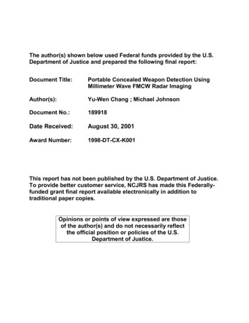
usually not easily visible; they may be located behind a wallor pillar. Second, even if the AP is visible, most of the accesspoints are encased by the manufacturer, making it difficult toknow the exact information of the antenna placements on theaccess point. Third and finally, even if we can estimate theantenna placements on the access point from the datasheetprovided by the manufacturer1 , the AP’s deployment orientation has to be carefully calibrated to the indoor maps withinan error of a few degrees. Thus, we need a system that canhelp in accurate mapping of the existing WiFi infrastructure,which does not involve any manual labor or time.In this paper, we present LocAP, an autonomous and accurate system to estimate access point location attributes –access point location, antenna placements, and deploymentorientation. We call this process of predicting accurate access point attributes as reverse localization. LocAP is the firstwork to establish the requirements for reverse localization asfollows:Accurate Access Point Locations: As shown in Figure 2a,any error in AP location is translated to an error in the locationof the user. So, any error exceeding a few tens of centimetersin access points’ location is going to adversely affect thedecimeter-level user localization. Thus, LocAP needs to locatethe access point accurate to within tens of centimeters.Accurate Antenna Separation: Different APs have differentantenna placement configurations and the angle made by theuser is measured at the access point using the spacing betweenantennas. So, any error in measuring antenna placements isgoing to cause a rotation error at the user. For example, errorin antenna separation by 4 mm causes 12o of error in the angleof user measured at the access point, which translates to up to1 m of error for a user 5 m away from the access point. Thus,LocAP needs to predict the antenna separation accurately towithin a few millimeters.Accurate Deployment Orientation: Finally, the accesspoints can be placed in any orientation in the environment.Any error in measurement of orientation directly translates tothe predicted angle subtended by the user at the access point.Hence even 10o of error in deployment orientation causes upto 90 cm of user location error for a user located just 5 maway from the access point. Thus, LocAP should resolve thedeployment orientation of the access point accurate to lessthan 10o of error.Automation: LocAP’s goal is to require no manual effortfor the reverse localization, and achieve the stringent requirements discussed earlier. Furthermore, there should be zeroeffort to associate these positions with the existing indoormaps, ideally in an autonomous way.LocAP achieves the aforementioned requirements and enables automated and accurate reverse localization of the access points. We achieve autonomy by deploying LocAP ona bot retrofitted with a multi-antenna WiFi device used in1 Datasheets,though publicly available do not talk about antenna placements or dimensions [6, 7, 17, 28, 47, 48, 57].1116Mislabelled AP locationActual AP ualPredicted user locationActual user tationFigure 2: LocAP’s Motivation: The user location is predicted wrong due to different errors in access point’s estimateddetails. (a) Translation: Predicting the wrong location of theAP. (b) Dilation: Predicting wrong antenna separation on theaccess point results in an error in angle estimated,(θobs 6 θexp )of the user. (c) Rotation: Predicting the wrong orientation ofthe AP.[8]. When deployed in a new environment, the bot first mapsthe physical environment. Next, it associates with existingAP infrastructure by collecting multi-antenna channel stateinformation, and pairing it with its predicted location in thephysical map as shown in Figure 1(left). LocAP uses thisinformation to build a database of the deployed WiFi infrastructure consisting of all the access point attributes meetingour stringent accuracy requirements. This database of accurate AP location attributes can then be used for decimeterlevel user localization as depicted in Fig. 1(right)The main technical contributions of LocAP to achieve theabove requirements can be summarized as follows:cm-accurate Access Point Localization: We make an important observation that accuracy of triangulation based WiFilocalization methods improves with an increasing numberof anchor points with known locations. In essence, creatingan array of 100’s of antennas measuring CSI at known locations achieves cm-level localization, which is not feasible inpractice2 . To overcome this, LocAP leverages the CSI datacollected by the bot at 100’s of predicted locations, mimicking 100’s of virtual antennas with known locations. However,these predicted locations suffer from a varying amount ofinaccuracy. Hence, LocAP designs a weighted localizationalgorithm, which weights each location-CSI data-point witha uniquely defined confidence metric capturing the accuracyof the predicted location.mm-accurate Antenna Geometry Localization: We haveseen earlier that both mm-error in antenna separation and error in deployment orientation lead to in-accurate Angle of Arrival (AoA) measurement at the access point, which impedesuser-triangulation. Thus, LocAP tackles antenna separationand deployment orientation together by achieving millimeter2 typicalindoor settings are 1000-2000 sq. ft., which would imply deploying an antenna every 100 sq. ft.17th USENIX Symposium on Networked Systems Design and ImplementationUSENIX Association
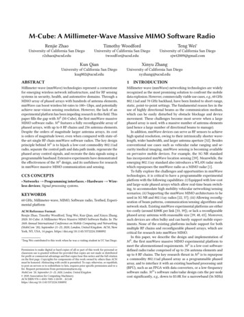
level accuracy in predicting the antenna geometry. The firstthought would be to use 1000’s of virtual antennas to achievecm-accurate localization [39] by locating individual antennageometry on the AP. But, this idea can only achieve accuracyat the cm-level and will not suffice to achieve mm-level detailsof the antenna geometry. Our key observation is to localize therelative antenna geometry between two antennas, primarilybecause the relative wireless channel between the two antennas can be measured very accurately by measuring their phaseinformation. The phase information is measured at the carrierfrequency level (λ 60 mm equivalent to 360o ), hence evenphase measurement accurate to 10’s of degrees achieves 1-2mm accuracy. However, this works for only relative antennaseparation d λ2 . LocAP designs a novel algorithm that usesrelative channel information across multiple bot locationsto solve for any antenna geometry, unrestricted by antennaseparation, to mm-level accuracy.Automation – Augmenting the SLAM algorithms: Toavoid any manual labor and errors, LocAP is deployed ona SLAM (Simultaneous Localization and Mapping) basedautonomous bot developed by us [8]. This bot provides uswith a physical map and the location and heading of the bot inthis physical map at all times. We pair these location-headingmeasurements with the CSI collected by the mounted WiFidevice. However, even the best of SLAM algorithms reportthe location to be in-accurate up to 10-20 cm, which can havea detrimental effect on the AP location attributes. Therefore,LocAP develops a confidence metric whose core idea to lookat the covariance of measurements across consecutive frames.Further, the implementation of LocAP does not need anymodification at the existing access points, as it is deployedon a custom made bot [8] that is mounted with a Quantennaclient. The Quantenna client readily reports the channel-stateinformation (CSI) of the associated access point. We evaluateLocAP in an indoor environment of 1000 sq ft area with multiple off-the-shelf access points and 2 different antenna configurations – rectangular and linear3 We achieved the followingresults satisfying the aforementioned accuracy requirements:Relative Antenna Geometry Prediction: LocAP’s relativereverse localization for the antenna separation has a median error of 3 mm (50 improvement), and a median error of 3o (8 improvement) for deployment orientation, while state-of-theart achieves a median error of 150 mm and 25o respectively.Access Point Localization: LocAP’s reverse localization ofthe access points achieves a median localization error of 13.5cm improving by 35% over the state-of-the-art WiFi localization algorithms [37].Case Study-User Localization: State-of-Art user localization is deployed using the access point attributes measuredmanually and with LocAP. We observe user localization errors of 78 cm and 50 cm respectively, a decrease in the errorof about 36%.3 theseconfigurations generalize the more generic antenna deploymentsfound on the commercial off the shelf WiFi access points.USENIX Association2Requirement and MotivationIt may seem natural that user localization algorithms [37, 53,59, 67] could be sufficient for reverse localizing the accesspoint’s location attributes – location, antenna geometry anddeployment orientation. Surprisingly, it turns out that requirements for reverse localization of the access are stringent. Todefine these requirements, we conduct empirical evaluationsfrom the standpoint on how various errors in AP attributes adversely affect the state-of-the-art decimeter level localizationalgorithms.Our empirical setup contains four access points, each with 4antennas, setup in a 25ft 30ft space. The user device is placedat 100 different locations while the access points locate theuser using an algorithm similar to [37]. Specifically, we aimto achieve decimeter-level localization accuracies for userWiFi localization algorithms and thus set a hardbound thatno more than 50 cm median error for user localization can betolerated.Error in the AP’s location Firstly, in the above-describedsetup, we incrementally increase the error in all the accesspoints’ locations. Next, we estimate the user location for eachof these erroneous access point locations and calculate theuser localization error. In Figure 3a, we plot the median userlocalization error across the access point errors reported. Wecan see that if the access point locations have an error of morethan a few centimeters, the median localization error startsto increase. From this, we can infer that the required level ofaccuracy for the reverse localization of APs should be in theorder of centimeters.Error in the antenna separation Second, AoA based localization algorithms make use of the relative phase informationbetween two antennas. Earlier, we have seen that the relative antenna position has to be estimated accurately to haveexact measurements of angles. Even when the access pointpositions are reported correctly, we can observe that the localization error increases with just a few millimeters of errorsin the reported relative antenna positions as shown in Figure3b. This observation is intuitive because the relative antennadistances are usually of the order of a wavelength of the transmitted signal, which in the case of WiFi is 6cm. So, any errorwhich is greater than a few millimeters is going to make ahuge difference in the relative phase measured at the accesspoint.Error in the Deployment Orientation Finally, the antennaarray can be oriented in any direction. It is also important toknow the exact deployment orientation of the antenna array.Errors in this orientation will proportionately affect the angle of arrival measurements made at the access points. Weobserve that the greater the error in deployment orientationprediction, the higher the median localization error becomesas shown in Figure 3c. From this plot, we can see that even 7owill degrade the median user localization accuracy to morethan 50 cm.17th USENIX Symposium on Networked Systems Design and Implementation1117
21.510.5010 -310 -210 -1Error in AP location (m)10 032.521.510.5010 -310 -210 -1Median Localization Error (m)2.5Median Localization Error (m)Median Localization Error (m)3Error in Antenna Location (m)(a)(b)32.521.510.500510Orientation Error (1520 )(c)Figure 3: Robustness of localization accuracy to Access Point (AP) location errors:(a) Shows that median localization errorincreases with increase in error of estimated AP location.(b) Shows how median localization error increases with increase in errorof estimated antenna locations. (c) Shows how median localization error increases with increase in error of estimated antennadeployment orientation.In summary, we should locate the access point’s locationwith less than 30 cm of error, the antenna separation within5 mm of error and the deployment orientation to less than7o of error. While these locations are typically mapped manually by humans using specialized equipment like VICON[55] or laser-based range finders [11], this process is timeconsuming, labor-intensive and error-prone. So, we need asystem that can accurately localize access points attributessatisfying these stringent requirements. Note that the moststringent requirements are the mm-accurate antenna separation and sub-7 degree deployment orientation. The state-ofthe-art [37, 39, 53, 67] localization algorithms can locate theindividual antennas to within a few 10 centimeters even bydeploying hundreds of AP’s in a given environment, which isinsufficient to determine the antenna geometry as per requiredspecifications established earlier in this section. Further, thereare relative localization algorithms [38, 61, 64] which trackthe user’s location across contiguous observations few millimieters apart. These ideas could potentially be used to find therelative antenna geometry. But, these tracking algorithmsassume that the two relative locations are less than λ/2 apart[6, 7, 17, 28, 47, 48, 57] but the antenna separations on mostaccess points are more than λ/2 apart, where there is an ambiguity that cannot be resolved. So, we design a system, LocAP,which fulfills these requirements and locates the access pointsand their antennas with the desired level of accuracy3DesignIn this section, we present the design of LocAP. Recall thatour main goal is to autonomously determine access points’location attributes within the reference coordinates of thephysical map to enable easily deploy-able WiFi-localization.LocAP deploys a SLAM based autonomous bot developedin [8] to map the environment. The autonomous bot providesit’s location and heading with respect to the environment’smap. Simultaneously, a four antenna WiFi device retrofitted1118on the bot, connects with the existing WiFi infrastructure,all the while reporting the CSI information at each instance.Furthermore, to avoid changes to deployed AP infrastructure,we perform all the processing on the bot. LocAP, therefore,is provided with the location and orientation of the bot withrespect to the physical map and the CSI data from the WiFidevice on the bot, which connects with the existing WiFiinfrastructure. We design LocAP to use these inputs to provideaccurate access point attributes–location, antenna separation,and deployment orientation with respect to the physical map.First, we discuss how to achieve the cm-level accurate location of the AP that also accounts for inaccuracies in reportedbot poses. Second, we present LocAP’s algorithm to estimatethe antenna separation and deployment orientation of all theAPs that needs to achieve the stringent requirement of mmlevel accuracy. In both of these scenarios, we assume wehave the CSI corresponding to the direct path and later in Section 3.3 we discuss how we tackle the presence of multipath inthe environment and recover the direct path’s CSI. Finally, wepresent the SLAM-based bot design, which does the best effort to provide the necessary measurements mentioned above.But often, these measured poses are not accurate. So, LocAPbuilds an algorithm which reports a confidence metric for eachmeasured pose. This confidence metric helps us surmount theerrors in the bot locations to calculate AP location attributes.3.1Locating the Access PointIn this subsection, we focus on identifying the position of oneof the access point’s antenna. This position of the antennawould then be representative of the access point’s locationand we refer to this as the first antenna in the subsequenttext. Recall that the access point’s location has to be estimated accurately to cm-level. A simple solution can be toutilize the existing WiFi localization approaches to locateone of the antennas on the access point, which would thenbecome the access point’s location. Unfortunately, state-of-17th USENIX Symposium on Networked Systems Design and ImplementationUSENIX Association
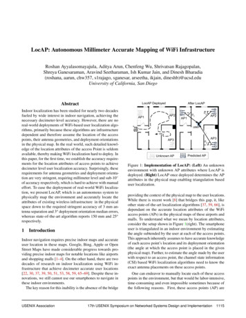
APfollows:min W (Sx1 t) 2y'x1yxBotFigure 4: First Antenna Localization: Gives an overview ofhow triangulation from 10s of bot locations locates the accesspoint accurately to within few centimeters.the-art localization algorithms only report decimeter levellocation estimates. However, we make an interesting observation: these algorithms show increasing location accuracieswith an increase in the number of access points deployed inan environment. In our scenario, we have a mobile bot whichcollects CSI data from the deployed access point at multiple anchors. This bot covers a large area setting up 100’s ofanchors which aids in cm-accurate first antenna localization.Owing to this setup of LocAP, we can employ an angle ofarrival estimation algorithm similar to [37] and estimate thethdirect path’s AoA, αbotp for p bot location (p 1, 2, . . . , P).We measure these AoA’s with respect to the bot’s local axis(X’-Y’) corresponding to the first antenna’s transmission foreach bot location u p [u p , v p ]. To enable this AoA based firstantenna triangulation, we should also know the direction ofthe bot’s heading (θ p ) with respect to the global axis (denotedby X-Y in Figure 4), which is reported by the bot as mentionedearlier. With (u p , θ p and αbotp ) we can find the first antennalocation as an intersection of P lines:Line p (y1 v p ) tan(90 (αbotp θ p ))(x1 u p ) (1)Ironically, the AoA based triangulation accuracy isbounded by the errors in the bot’s reports of its location,(u p , v p ) and heading, θbotp . Clearly, this creates a vicious unending loop – to predict the antenna locations we need accurate bot measurements and vice-versa to predict the bot’slocations. To overcome this problem, we take advantage ofSLAM algorithms [21] to get accurate ground truth estimatesof the bot location and heading. Unfortunately, SLAM-basedbots do not have 100% confidence in all the location estimatesthey report, forcing us to only cherry-pick the measurementswhich we believe are accurate. Based on this intuition, wedesign a confidence metric, w p [0, 1] for each bot locationu p . Further details on the design of the confidence metric arediscussed in Section 3.4. This confidence metric implies thatthe bot is more confident with the reported pose the closerit is to one. We thus implement a low-confidence rejectionalgorithm, which rejects the measurements with confidences,w p , in the lowest 20% (Using only b0.8 Pc lines).We use these confidences in combination with the rest ofour b0.8 Pc line equations to define a weighted least squaresproblem to optimally solve for the first antenna location asUSENIX Association(2)where x1 [x y]T is the first antenna location,W diag(w1 , w2 , · · · , w0.8P ) is the weight matrix,TS(p, :) [cos(αbot sin(αbotandp θp)p θ p )]bot θ )]. Thus, wet(p) [u p cos(αbot θ) vsin(αpppppestimate of the first antenna’s location x1 which correspondsto the access points location.3.2Determining Antenna Separation and Deployment orientationAs described above, we can leverage the motion of the bot toidentify the accurate location of one antenna on the accesspoint. One might wonder if it is possible to apply this algorithm iteratively to identify the location of each antenna onthe access point and hence recover the relative placement ofantennas. However, it is not so straightforward. In particular,the geometry prediction needs to be an order of magnitudemore accurate than the location prediction. While it sufficesto measure the location of the access point to cm-level, thegeometry, i.e. the relative position of antennas, needs to bemm-accurate. While combining across 10s of bot locationsprovides antenna location accurate to cm-level, it does not extend to mm-accurate antenna geometry by combining across100s or even 1000s of bot locations as shown in the prior art[39]. This problem occurs owing to the asynchronous clocksbetween the access point and the bot’s WiFi device whenmeasured at a single antenna at the access point.To overcome this problem we make a key observation- in contrast to the phase measured at one antenna on theaccess point, the relative phase across two antennas is rid ofsynchronization errors as they share the same clock. Further,at WiFi 11ac’s 5GHz carrier frequency, a wavelength of 6 cmcorresponds to a phase difference of 2π radians. Empirically,we have observed that we can easily resolve phase differencesup to π/18 radians (10o ), which facilitates measurement ofthe distance between two antennas with a resolution of 2 mm,thus enabling us to locate the antenna geometry accuratelyto within few millimeters. Hence, our first key insight is tomeasure the relative antenna separations, di , and deploymentorientations, ψi , for all the NAP antennas on the access pointwith respect to the first antenna (i 2, 3, . . . , NAP ).Unfortunately, although the relative phase information canresolve relative antenna separation to within 2mm, it cannotresolve for antenna separations greater than λ/2. To furtherunderstand this, consider an example scenario where the botis moving in a circular arc about the two-antenna access pointin steps of small angles as shown in Figure 5a. To avoid overcrowding of subscripts, we consider a two antenna accesspoint and drop the access point’s antenna indexing, i. Similaranalysis can be performed pairwise on all the antennas onthe access point with respect to the first antenna. Now, to17th USENIX Symposium on Networked Systems Design and Implementation1119
x- /2d/ 0.5d/ 1d/ 1.5/4/23 /450-5- /2- /4/40Orientation of the bot,(a)10d/ 1.5/d )0d/ 1Slope (dd sin( )/AP 2y/2Phase diffBotd/ 0.5/2-10(radians)0Orientation of the bot,(b)(radians)(c)Figure 5: Estimating AoD from phase difference: (a) A sample case where the bot is in circular arc around the AP (b) Phasedifference φ vs the orientation of the bot β assuming the deployment orientation of the AP, ψ 0 (c) Slope d φdβ vs the orientationof the bot β when compensated for the orientation of the access point.locate the second antenna with respect to the first antenna, weanalyze relative phase across these two antennas. We knowthat for the bot’s location, u p , the phase difference betweenthese two antennas corresponding to the direct path, φ p , canbe estimated as: 2πd φ p modsin(90 (β p ψ)), 2π(3)λwhere, the parameters of interest ψ and d are antenna deployment orientation (with respect to the X-axis) and antennaseparation respectively. β p is the angle subtended by thebot’s location at the access point with respect to the globalX-axis. From the inset in Figure 5a, we can see that the angleof departure from the AP is given by αAPp 90 (β p ψ)(4)and the extra distance travelled (represented by the red-dashedsegment) is given by d sin(αAPp ). This extra distance travelledinduces the phase difference given in Equation 3. Thus, thephase difference across two antennas can help us estimatethe antenna separation, d and deployment orientation ψ. Tobetter understand this relation, we plot φ p for all the botlocations along the circular arc against the angle subtendedby the bot, β p , for various antenna separations d in Figure 5b.From this plot we can see that for d λ/2, we have a uniquemapping between the phase difference, φ p , and the bot’slocation, but for d λ/2 we have ambiguous solutions thatprevents us from estimating d and ψ. The ambiguity occursbecause the phase difference we measured is a modulus of2π, which means for a given φ p , the actual phase differencecan be 2n p π φ p , where n p is any positive integer. Thismeans we have three unknowns, (d, ψ, n p ) to solve for, given asingle phase difference value, φ p . Furthermore, even for eachadditional bot location we have a new φ p 1 estimate, we alsoadd an extra unknown n p 1 making it impossible to uniquelysolve for d and ψ. LocAP’s key insight is that, in contrastto the phase difference φ p , the differential phase difference1120with respect to the bot’s angle at the AP (β p ) for optimallysmall increments of β p , has a unique one-to-one mapping asshown in Figure 5c. So, the second key observation we makeis that while the phase difference is not uniquely solvable ford λ/2, the differential phase difference is uniquely solvable.Intuitively, two close bot positions will have the similar phasewrap-around’s, and hence, taking the difference of the phasedifferences, φ p2 φ p1 , can eliminate the ambiguity.So far we have considered that the bot is moving along acircular trajectory. In fact, LocAP does not restrict the bot’smotion to a circular arc and can work with arbitrary motion,as long as the CSI is measured regularly. To understand theexact implementation of LocAP’s relative antenna geometryprediction, we consider a more free-flow path as shown in Figure 6. Concretely, determining the relative antenna geometryrequires two parameters – the distance between antennas, d,and the deployment orientation of the antenna array, ψ, as canbe seen from Figure 6. The bot moves to P distinct locationsalong a pre-determined trajectory about the AP and collects aseries of P CSI measurements, H p (p 1, 2, · · · , P), while simultaneously reporting the bot’s locations, u p . The bot makesan angle β p with respect to the global X-axis. Next, for eachposition of the bot, u p , we evaluate the differential phase difd φference dβ pp between the two antennas on the access point.Differentiating Equation 3, we getd φ2πd2πd cos(90 (β ψ)) sin(β ψ) (5)d
help in accurate mapping of the existing WiFi infrastructure, which does not involve any manual labor or time. In this paper, we present LocAP, an autonomous and ac-curate system to estimate access point location attributes - access point location, antenna placements, and deployment orientation. We call this process of predicting accurate ac-