Transcription
Amazon Redshift Connector BestPractices Copyright Informatica LLC 2019, 2022. Informatica, the Informatica logo, and Informatica Cloud are trademarksor registered trademarks of Informatica LLC in the United States and many jurisdictions throughout the world. Acurrent list of Informatica trademarks is available on the web at https:// www.informatica.com/trademarks.html.
AbstractThis article contains information about how to configure Amazon Redshift Connector, PowerExchange for AmazonRedshift, and PowerExchange for Amazon Redshift for PowerCenter to get the best performance and efficiency.This document captures the concepts, best practices, and recommendations for tuning Informatica Cloud, Big DataManagement, and PowerCenter for using Amazon Redshift. These best practices have been derived from real-worldexperiences that covers different use cases.Supported Versions Informatica Cloud Amazon Redshift Connector PowerExchange for Amazon Redshift 10.2 or later PowerExchange for Amazon Redshift for PowerCenter 10.2 or laterTable of ContentsOverview. . . . . . . . . . . . . . . . . . . . . . . . . . . . . . . . . . . . . . . . . . . . . . . . . . . . . . . . . . . . . . . . . . 3Amazon Redshift Overview. . . . . . . . . . . . . . . . . . . . . . . . . . . . . . . . . . . . . . . . . . . . . . . . . . . . . . 3ETL and ELT Overview. . . . . . . . . . . . . . . . . . . . . . . . . . . . . . . . . . . . . . . . . . . . . . . . . . . . . . . . . 4Use Cases. . . . . . . . . . . . . . . . . . . . . . . . . . . . . . . . . . . . . . . . . . . . . . . . . . . . . . . . . . . . . . . . . 5Batch Data Integration. . . . . . . . . . . . . . . . . . . . . . . . . . . . . . . . . . . . . . . . . . . . . . . . . . . . . . . 5Streaming Data into Amazon Redshift . . . . . . . . . . . . . . . . . . . . . . . . . . . . . . . . . . . . . . . . . . . . . 6Mass Ingestion Task to Upload Data into Amazon S3 or Amazon Redshift. . . . . . . . . . . . . . . . . . . . . . 7Amazon Redshift Connectivity Architecture Overview. . . . . . . . . . . . . . . . . . . . . . . . . . . . . . . . . . . . . 7Security. . . . . . . . . . . . . . . . . . . . . . . . . . . . . . . . . . . . . . . . . . . . . . . . . . . . . . . . . . . . . . . . . . 8Sign-In Credentials . . . . . . . . . . . . . . . . . . . . . . . . . . . . . . . . . . . . . . . . . . . . . . . . . . . . . . . . . 8Access Management . . . . . . . . . . . . . . . . . . . . . . . . . . . . . . . . . . . . . . . . . . . . . . . . . . . . . . . . 9VPC. . . . . . . . . . . . . . . . . . . . . . . . . . . . . . . . . . . . . . . . . . . . . . . . . . . . . . . . . . . . . . . . . . . 9SSL Connections . . . . . . . . . . . . . . . . . . . . . . . . . . . . . . . . . . . . . . . . . . . . . . . . . . . . . . . . . . 9Data Encryption. . . . . . . . . . . . . . . . . . . . . . . . . . . . . . . . . . . . . . . . . . . . . . . . . . . . . . . . . . . . 9Amazon S3 Upload Optimizations. . . . . . . . . . . . . . . . . . . . . . . . . . . . . . . . . . . . . . . . . . . . . . . . . 10SSL Configuration on Cloud. . . . . . . . . . . . . . . . . . . . . . . . . . . . . . . . . . . . . . . . . . . . . . . . . . . 11Transformation Tuning. . . . . . . . . . . . . . . . . . . . . . . . . . . . . . . . . . . . . . . . . . . . . . . . . . . . . . . . 12Partitioning. . . . . . . . . . . . . . . . . . . . . . . . . . . . . . . . . . . . . . . . . . . . . . . . . . . . . . . . . . . . . . . 12Partitioning on Cloud. . . . . . . . . . . . . . . . . . . . . . . . . . . . . . . . . . . . . . . . . . . . . . . . . . . . . . . 13Partitioning on PowerCenter . . . . . . . . . . . . . . . . . . . . . . . . . . . . . . . . . . . . . . . . . . . . . . . . . . 14Data Compression. . . . . . . . . . . . . . . . . . . . . . . . . . . . . . . . . . . . . . . . . . . . . . . . . . . . . . . . . . . 15Keys. . . . . . . . . . . . . . . . . . . . . . . . . . . . . . . . . . . . . . . . . . . . . . . . . . . . . . . . . . . . . . . . . . . . 16Distribution Keys. . . . . . . . . . . . . . . . . . . . . . . . . . . . . . . . . . . . . . . . . . . . . . . . . . . . . . . . . . 16Sort Keys. . . . . . . . . . . . . . . . . . . . . . . . . . . . . . . . . . . . . . . . . . . . . . . . . . . . . . . . . . . . . . . 16Primary & Foreign Keys. . . . . . . . . . . . . . . . . . . . . . . . . . . . . . . . . . . . . . . . . . . . . . . . . . . . . . 17Analyze and Vacuum Target Table. . . . . . . . . . . . . . . . . . . . . . . . . . . . . . . . . . . . . . . . . . . . . . . . . 172
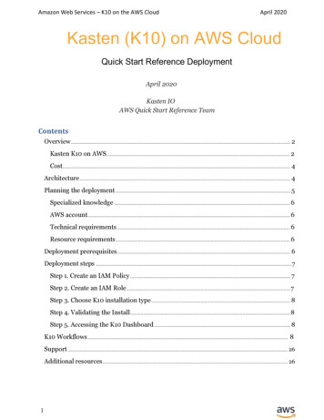
Reading Data From a Non-Amazon Redshift Source. . . . . . . . . . . . . . . . . . . . . . . . . . . . . . . . . . . . . . 17Configure Amazon Redshift Workload Management. . . . . . . . . . . . . . . . . . . . . . . . . . . . . . . . . . . . . 18Rules and Guidelines for Configuring Amazon Redshift Workload Management. . . . . . . . . . . . . . . . . . 19Pushdown Optimization. . . . . . . . . . . . . . . . . . . . . . . . . . . . . . . . . . . . . . . . . . . . . . . . . . . . . . . 19Benefits of Using Pushdown Optimization. . . . . . . . . . . . . . . . . . . . . . . . . . . . . . . . . . . . . . . . . . 20Rules and Guidelines for Using Pushdown Optimization . . . . . . . . . . . . . . . . . . . . . . . . . . . . . . . . . 20Data Types and Load Patterns. . . . . . . . . . . . . . . . . . . . . . . . . . . . . . . . . . . . . . . . . . . . . . . . . . . 21Rules and Guildelines for Connecting to Amazon Redshift. . . . . . . . . . . . . . . . . . . . . . . . . . . . . . . . . . 21OverviewYou can use Amazon Redshift and Informatica Cloud, Big Data Management, or PowerCenter to rapidly and costeffectively build a cloud first data warehouse. Then, extend your data warehouse to any on-premises or to other datasources. With the connectivity and power of this solution, you can deliver the data-driven agility required for businesssuccess today and tomorrow.Amazon Redshift is one of the first data warehouse to offer a massively parallel, distributed, columnar, relational datastore that is incredibly fast and can analyze billions of rows of data. You can create an Amazon Redshift cluster in fewminutes and can scale as data volumes increases easily.While data warehouse on cloud offers power and scale for analyzing petabytes of data, you still need to apply thefundamental data management processes such as data integration, data quality, data masking, data governance,master data management to the data present in the data warehouse. Transferring of on-premises data to the cloud is abig undertaking task that needs to be done efficiently to maximize the benefits of the data warehouse. Loading largedata sets take a long time and consumes huge computing resources. The data integration workflows such as ETL orELT job needs to run quickly and load the data sets in the right format into the data warehouse to avoid slow analyticqueries.Informatica Intelligent Enterprise Cloud Data Management offers a complete data management solution for AmazonRedshift that covers data integration (ETL or ELT), data quality, data masking, data security, streaming, mass migration,master data management, and data governance.You can enhance the security to secure and protect the data. You can optimize the performance and allows optimumutilization of the system resources to achieve fast query execution when you read data from the source and write datato the target. The following lists the features that you can use to optimize the performance: Security enhancements Transformation Tunning Partitioning Distribution Key, Primary Key, and Sort Key Analyze and Vacuum target tableAmazon Redshift OverviewAmazon Redshift is a cloud-based petabyte-scale distributed data warehouse that the organization uses to analyze andstore data.Amazon Redshift uses columnar data storage, parallel processing, and data compression to store data and to achievefast query execution. Amazon Redshift distributes data across a cluster of compute nodes and processes the nodes inparallel.3
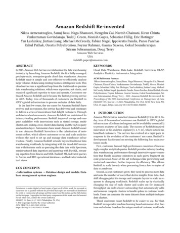
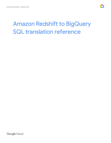
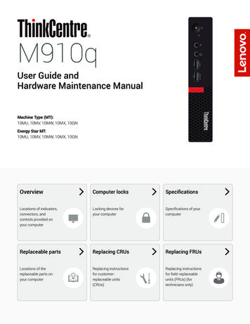
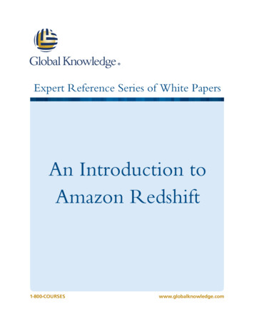
Amazon Redshift uses a cluster-based architecture that consists of a single leader node and compute nodes. Theleader node manages the compute nodes and communicates with the external client programs. The leader nodeinteracts with the client applications and communicates with compute nodes. The leader node takes query requestssuch as JDBC or ODBC interface, performs query planning, and then distributes the SQL query across compute nodesfor massive scale and performance.A compute node stores data and runs queries for the leader node. Any client that uses a PostgreSQL driver cancommunicate with Amazon Redshift. The ANSI standard SQL interface makes it easy to point Business Intelligenceand Analytics Visualization tools at Amazon Redshift for interactive analytic queries.The following image shows the overview of an Amazon Redshift cluster:ETL and ELT OverviewETL (Extract, Transform, and Load) and ELT (Extract, Load, and Transform) are methods used to transfer data from asource to a data warehouse.The ETL approach is ideal for transferring external data from either a single source or combined heterogeneoussources into Amazon Redshift cluster. Amazon Redshift recommends that you load the data to Amazon Redshiftthrough Amazon S3 staging location as this approach is the fastest data ingestion option into Amazon Redshift. TheETL approach reads and writes data at high speeds. This allows faster data processing and performing complexcalculations in less time to read from or write to disk.Note: In the ETL approach, memory space of the staging location is the only limiting factor.However, after loading the data to the Amazon Redshift cluster, you must use a different data transformation approachto transform. Then, move the data across staging location, intermediate, and analysis Amazon Redshift tables in thesame Amazon Redshift cluster. Once the data is in the Amazon Redshift cluster, the ETL pattern of moving data in andout of Amazon Redshift tables within the same Amazon Redshift cluster through Amazon S3 is often sub-optimal. Usethe ELT approach of pushing the data transformation operations to execute as SQL operations by the Amazon Redshiftlayer to optimize the process. The ELT approach optimises the process because the data is already available in thedata warehouse and the data transformation operations such as filter, join, aggregation, or sorting are supported at theSQL layer enabling faster data processing.In Informatica, the ELT approach is referred to as SQL Pushdown and Amazon Redshift Full SQL Pushdown issupported in the Informatica Cloud platforms. Informatica supports both ETL as well as ELT approach and provides theoption to the users to choose based on the scenario.4
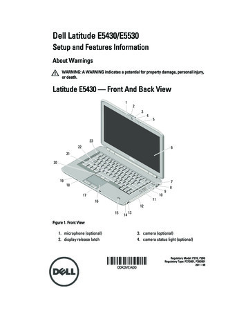
The following image illustrates the ETL and ELT approaches:Use CasesThe database administrators, who are well-versed with relational database constructs find it easy to create andprovision new Amazon Redshift nodes and clusters. However, when you load data to Amazon Redshift, writing manualSQL scripts can make the loading hard to be agile and adapt to rapidly change the requirements from businessstakeholders.The following are the use cases: Batch Data Integration Streaming Data into Amazon Redshift Mass Ingestion task to upload data to Amazon S3 and Amazon RedshiftBatch Data IntegrationWhen the data warehouse is in the same network as the source data, the data flow patterns can involve multipleinteractions with the data warehouse.Even though data are loaded to the data warehouse in batches, data are loaded to the data warehouse in a record-levelinteraction such as lookups or customized update statements. With the data warehouse on cloud, it is important toaddress the record-level interactions to ensure if you can perform read or write operation in bulk. As Amazon Redshiftis best suited for bulk insert, update or read operation, you must design the mapping to perform such bulk operations.The recommended data load patterns for the data warehouse involves staging of data from the source first bytransforming the data before or after loading (ETL or ELT) to the staging location. Informatica conforms to the AmazonRedshift best practices and implements several of the recommendations in the Amazon Redshift Connector,PowerExchange for Amazon Redshift adapter, and PowerExchange for Amazon Redshift for PowerCenter adapter.The data fetched from on-premises and cloud sources are staged in Amazon Redshift mostly with few transformationssuch as filters that makes sure that only the required data are fetched. By default, data are staged on Amazon S3.However, Informatica recommends that you stage the data to Amazon Redshift directly.Note that the staging of data to Amazon S3 is an internal step performed to follow the AWS recommendations forperformance. In this case, we are discussing about the logical staging of source data in an Amazon Redshift table. Youcan even choose to use an SQL query when you load the data. Such staging is performed by splitting the data intomultiple threads and loading the data to the staging area in parallel. Informatica also uses the node and sliceinformation to configure the number of threads.5
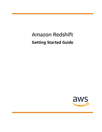
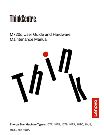
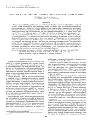
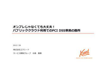
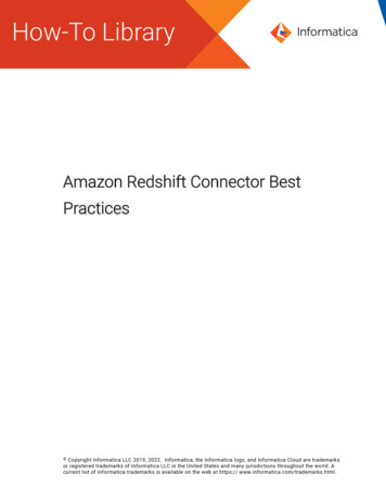
For all source data that resides on cloud, you can use the Informatica Secure Agent. For any data that resides insidethe firewall, Informatica recommends that you download the Informatica Secure Agent. Once the data is in the stagingarea, depending on the design, the data can be either processed through an intermediate steps or loaded directly intothe data warehouse table. These steps can be designed using Mapping Designer and at the run time. You can chooseto run the mapping either using Informatica Secure Agent (ETL) or Amazon Redshift SQL (ELT).The following image illustrates the batch data integration:While the image shows an Amazon Redshift staging storage and an intermediate Amazon Redshift storage, the stagingof the data largely depends on the data transformation patterns. In most of the cases, you might need to stage the datain one of the staging locations.Streaming Data into Amazon RedshiftStreaming messages are ingested by Informatica Edge Data Streaming using Kinesis or Kafka processed byInformatica Big Data Streaming.You can perform streaming data processing to enrich or refine the messages and then use Kinesis to consume thesteaming data from Informatica Big Data Streaming. Kinesis can be configured to write the steaming data to AmazonS3 from where the steaming data undergoes further batch processing through Informatica Big Data Streaming or anyother tool.The following image illustrates the streaming data integration into Amazon Redshift:6
Mass Ingestion Task to Upload Data into Amazon S3 or Amazon RedshiftOn cloud, as more and more companies wants to create data lakes in addition to the data warehouse, it has become acommon requirement to upload data from various sources to a data lake, such as a data lake on Amazon S3.Once the data is available in the data lake, you can process data and load the data in the data warehouse. In the datawarehouse, the data are stored in a structured way that is more suitable for conventional analytics and data scientistscan use the data lake for huge data analyses.In addition to the data that is in applications, such as ERP, CRM, or database, nowadays most of the companies storedata in various file formats, such as Avro, CSV, ORC, JSON, and Parquet. It is common to have large amount of files thatare generated or received from the third-parties or other applications on a regular basis. You typically want ongoingloads set up for such files that can provide Managed File Transfer (MFT) features as data are loaded to the data lake.On cloud, you can use mass ingestion tasks on Informatica Intelligent Cloud Services to upload a large number of filesof any file type between on-premises and cloud repositories, and track or monitor file transfers. You can upload filesfrom any file container, such as local folders, FTP folders, or Amazon S3 bucket using a name or expression pattern.You can also upload files to Amazon S3 or Amazon Redshift staging location directly at once, instead of moving singlerow of data separately. When you create a mass ingestion task to upload files, you can perform the Managed FileTransfer (MFT) features, such as encryption, compression, override, and rename.The following image illustrates the mass ingestion task to upload data to Amazon S3 or Amazon Redshift staginglocation:Amazon Redshift Connectivity Architecture OverviewWhen you use Amazon Redshift Connector, PowerExchange for Amazon Redshift, and PowerExchange for AmazonRedshift for PowerCenter to read data from sources, the data are read using multiple partitions that can be configuredeither using specific values, ranges of values, or partition specific queries. Then, the data are processed in parallel toapply any transformations that you configure.The metadata are fetched from Amazon Redshift based on the number of slices in the compute nodes and splits thedata accordingly. The source side partitions can split the data into several stage files that are written in parallel.The files are loaded into Amazon S3 staging location in parallel with each file uploaded as a single part of multi-partbased on the size. Then, loads the data from these files into the Amazon Redshift table by running the COPYcommand.7
The following image shows how data is read from the source, loaded in the Amazon S3 staging file, and written to theAmazon Redshift target:SecurityYou can secure and protect the data when you read data from the source and write data to the target. You can enhancethe security for the Amazon Redshift clusters, data in-transit, and data at-rest.Sign-In CredentialsAt the database level, users are authenticated using the user name and password credentials when the connection isestablish with Amazon Redshift.The users can be of the following types: Superuser: A superuser user is the master user name that you create when you launch the Amazon Redshiftcluster. Using this user name, you can query system tables, views, or catalog tables. User: A user name that is used to access the cluster. Based on privileges of the user, you can perform select,insert, update, delete, create, or reference operations.The following image shows the sign-in credentials page:8
Access ManagementAt cluster level, there are two security management options available to prevent unauthorized access.The following lists the security management options: Role Based Access: With AWS Identity and Access Management (IAM) Role, you can securely control accessto Amazon Redshift resources for the users in your AWS account. If you have multiple users that requireaccess to Amazon Redshift, create an IAM Role for each users and provide a specific access policies to eachusers. You do not have to share your credentials. For more information about how to create an IAM Role andadd IAM Role to a cluster, see the AWS documentation. Key Based Access: You can provide the Access Key ID and Secret Access Key for all the users with IAM Rolethat are authorized to access the Amazon resources that contains the data.The following image shows the Access Key ID and Secret Access Key connection properties:Note: Informatica recommends that you use the IAM Role based access option to access resources andsensitive data.VPCTo protect the cluster access using a virtual networking environment, you can launch the cluster in an Amazon VirtualPrivate Cloud (VPC).You can use the Amazon S3 VPC endpoints. Amazon S3 VPC endpoints are easy to configure, highly reliable, andprovides a secure connection to Amazon S3 that does not require a gateway or NAT instances.The EC2 instances that runs in the private subnets of a VPC have controlled access to Amazon S3 buckets, objects,and API functions that resides in the same region as the VPC. You can use an Amazon S3 bucket policy to indicatewhich VPCs and VPC endpoints have access to the Amazon S3 buckets.SSL ConnectionsYou can use the Secure Sockets Layer (SSL) connections to encrypt data and validate the server certificate that youconnect to.The SSL connections ensure that all JDBC calls to Amazon Redshift, such as data preview, UNLOAD, and COPYcommands goes through the SSL encrypted connection. For more information about how to set up Secure Agent tosupport SSL enabled connections with Amazon Redshift, see the AWS documentation.Data EncryptionYou can encrypt data while loading the table data as staging files to Amazon S3.When you read data from an Amazon Redshift source, you can select one of the following encryption types: Server-side encryption with Amazon S3-managed keys (SSE-S3) Client-side encryption with a customer-managed key (CSE-CMK)When you write data to an Amazon Redshift target, you can select one of the following encryption types: Server-side encryption with Amazon S3-managed keys (SSE-S3) Server-side encryption with AWS KMS-managed keys (SSE-KMS)9
Client-side encryption with master symmetric key.To encrypt data using AWS KMS-managed keys, you must provide the customer master key ID when you configure theAmazon Redshift connection.Amazon S3 Upload OptimizationsWhen you upload data to Amazon S3, you can optimize the performance.To optimize the performance, use the following methods:Compress data before uploading to Amazon S3When you read data from a source, local staging files are created before you upload the data to Amazon S3.You can use the multiple compression format to compress the data. When you write data to the target, thefiles are decompressed. Even though compression and decompression process is a CPU-intensive task, youcan optimize the performance when you load large amounts of data to Amazon S3.Encrypt data before uploading to Amazon S3You can encrypt the data before you upload the data to Amazon S3. You can use either the client-side orserver-side encryption to encrypt the data when you write data stored in Amazon S3 to Amazon Redshifttarget.Uploads file to Amazon S3 in parallelYou can upload files to Amazon S3 in parallel. The Secure Agent, Data Integration Service, or PowerCenterIntegration Service uses the data available in the compute nodes of the Amazon Redshift cluster todetermine how to split the files and upload the files to Amazon S3. The number of files staged and uploadedin parallel is a combination of the partitions used in the mapping and the number of slices in the computenodes.The Secure Agent, Data Integration Service, or PowerCenter Integration Service processes data in parallel forthe partitioned mapping.Parallelizing Copy to Amazon RedshiftWhen you write data from Amazon S3 to Amazon Redshift target, you can split up the data into multipleslices that are equal to or greater than the number of slices in the cluster. Then, load the data in parallel witheach slices taking the data from its own dedicated file.10
The following image shows how the data are uploaded to Amazon S3 and written to Amazon Redshift target:SSL Configuration on CloudOn cloud, you must configure the Secure Agent to support an SSL connection to Amazon Redshift.Perform the following step to configure the Secure Agent:1.Download the Amazon Redshift certificate from the following ds/redshift-ssl-ca-cert.pem2.Run the following command to add the certificate file to the key store: {JAVA HOME}/bin/keytool - keystore {JAVA HOME}/lib/security/cacerts -import -alias string value -file certificate filepath 3.On the Data Integration, click Configure Runtime Environment.4.In the Actions tab, click Edit.The Edit Secure Agent page appears.5.In the System Configuration Details section, set the value of the Type to DTM.6.Click Edit Agent Configuration icon and add the following value for JVMOption1:Djavax.net.ssl.trustStore keystore name 7.Click Edit Agent Configuration icon and add the following value for JVMOption2:Djavax.net.ssl.trustStorePassword password 8.Add the following parameter in the JDBC URL that you specify in the Amazon Redshift connection property:ssl trueFor example,jdbc:redshift://mycluster.xyz789.us-west- 2.redshuft.amazonaws.com:5439/dev?ssl true9.11Click OK.
Transformation TuningWhen you initialize a mapping, blocks of memory are allocated to hold the source and target data. If enough memoryblocks to hold the data are not allocated, the mapping fails.The DTM buffer is a temporary storage area used to store temporary data for caching data used by transformation. Thebuffer is divided into blocks. The buffer size and block size for a mapping are tunable. If the performance of read, write,or any transformations are slow, this is an indication that DTM buffer tuning is required.You must tune the DTM buffer size and buffer block size for optimal throughput in the following manner:Default Buffer Block SizeTo adjust the buffer block size, use the following code:Buffer Block Size sum of all column widths (in bytes) * n,where n is a positive integer 1In the advanced session property, select the Default buffer block size option and set the required value. Thefollowing image shows the Default buffer block size advanced session property:DTM Buffer SizeTo adjust the DTM buffer size, use the following code:DTM Buffer Size Buffer Block size * m,Where m is a positive integer 1In the advanced session property, select the DTM Buffer Size advanced session propertyoption and set therequired value. The following image shows the DTM Buffer Size advanced session property:Note: The DTM buffer size is based on the size of the row and data. If data partitioning is enabled, the DTM buffer sizeis the total size of all memory buffer allocated to all partitions. For a mapping that contains n numbers of partitions, setthe value of the DTM Buffer Size option to at least n times for the mapping with one partition.PartitioningOn cloud and PowerCenter, you can partition the data to optimize the performance and allows optimum utilization ofthe system resources.Apart from configuring the DTM buffer size, buffer block size, and batch size to optimize the performance, you canfurther improve the performance at the external sources, targets, or transformations level. External source or targetconnection performance is more dependent on external application optimization, network latency, DTM buffer blocksize, and commit interval. The transformation level optimization is related to I/O operations and partitions, or partitionspoints.Informatica supports creation of parallel data pipelines with a thread-based architecture. The partitioning of dataacross the parallel data pipelines is handled automatically. The partitioning option executes optimal parallel mappingby dividing the data processing into subsets, which runs in parallel and are spread among available CPUs in amultiprocessor system.12
Unlike the approaches that require manual data partitioning, the partitioning option automatically guarantees dataintegrity because Informatica provides parallel engine that dynamically realigns data partitions for set-orientedtransformations. Configurable mapping options, such as error handling, recovery strategy, memory allocation, andlogging makes the mapping easier to gather statistics used to maximize the performance. By enabling the hardwareand software to scale for handling large volumes of data and users, the partitioning option improves the performanceand productivity.Amazon Redshift Connector supports pass-through and key-range partitioning. PowerExchange for Amazon Redshiftfor PowerCenter supports pass-through partitioning.Informatica partitioning for Amazon Redshift follows the principle of serializable isolation. This enable you to run twoconcurrently transactions T1 and T2, giving the same results as at least one of the following:1.T1 and T2 run serially in that order.2.T2 and T1 run serially in that order.The following image shows how the source data are partitioned and loaded to the target:Partitioning on CloudWhen you read data from an Amazon Redshift source, Informatica recommends that you use the key-rangepartitioning. The key can be based on a column or a set of columns that are distributed across partitions evenly andacross the compute nodes of the Amazon Redshift cluster.When the key column that you select for the source partitioning is same as the distribution key of the Amazon Redshiftcluster, the Secure Agent reads the data faster.13
Amazon Redshift Connector supports the following partitions: Pass-through partitioning: You can specify the number of partitions when you read flat file sources.The following image shows an example of the Pass-Through Partitioning tab: Key-Range partitioning: With key-range partitioning, the number of source partitions you need to createdepends on the Amazon Redshift cluster workload management concurrency setting. By default, the value is 5.If the value is set to the default value, you must create five partitions on the source side.The following image shows the Key-Range Partitioning tab:Partitioning on PowerCenterIf you need to extract a large amount of source data, you can partition the sources to improve session performance.Partitioning sources allows the PowerCenter Integration Service to create multiple connections to sources and processpartitions of source data concurrently. You can partition sources if the PowerCenter Integration Service can maintaindata consistency when it processes the partitioned data.By default, the Workflow Manager sets the partition type to pass-through for Amazon Redshift tables. In pass-throughpartitioning, the PowerCenter Integration Service passes all rows at one partition point to the next partition pointwithout redistributing them.If you create multiple partitions for an Amazon Redshift source session, the PowerCenter Integration Service evaluatesthe session properties in the following order to run the session: SQL Query INFA Advanced Filter Slices
Redshift, and PowerExchange for Amazon Redshift for PowerCenter to get the best per formance and efficiency. This document captures the concepts, best practices, and recommendations for tuning Informatica Cloud, Big Data Management, and PowerCenter for using Amazon Redshift. These best practices have been derived from real-world