Transcription
Proceeding of Marine Safety and Maritime Installation (MSMI 2018)The Implementation of API RP 1102 Code to EvaluateGas Pipeline Road CrossingNurhadi Siswantoro1,a,*, Muhammad Badrus Zaman1,b, Semin1,c, and Dwi Priyanta1,d1Department of Marine Engineering, Institut Teknologi Sepuluh Nopember, Surabaya, Indonesiaa. nurhadisukses@gmail.com, b. drus zaman@yahoo.com, c. seminits@gmail.com,d. priyanta@gmail.com*corresponding authorKeywords:API RP 1102; Gas Pipeline; Road Crossing; and Stress AnalysisAbstract: This paper discussed about evaluation stress on gas pipeline. A pipelinetransports LPG (Liquefied Petroleum Gas) from jetty to storage tank area along 1200meters. The pipeline has nominal pipe size (NPS) 10 inches and buried in areas with highpopulation levels (areas with high consequences). At KP 800 meter the segment of pipelinehas road crossing conditions, where vehicles such as heavy vehicles pass across above.Pipeline has operated during about 8 years, it necessary study to evaluate the integrity orstrength. One of the methods to evaluate buried and road crossing pipelines is determiningstress occurs. Stress analysis for pipeline road crossing is evaluated using code API RP1102 (Pipelines Crossing Railroads and Highway). Based on these standards, the pipelineroad crossing is evaluated by stress components such as (a) Circumferential Stress, (b)Longitudinal Stress, (c) Radial Stress. The calculation will be analysed using spreadsheetmodelling. Based on the stress analysis in existing operational condition, the segment in KP800 is Acceptable according Standard API 1102. All parameters show acceptable,furthermore the pipeline is concluded in satisfactory condition.1. IntroductionTerminal LPG company involved in the services of receiving, stockpiling and distributing theLPG. The company has responsible for ensuring its assets in high integrity. The process ofreceiving, stockpiling and distributing the LPG. The company has responsible for ensuring its assetsin high integrity. The process of receiving, stockpiling and distribution starts from the Jetty head,which functions to carry out receipts from Tanker. In the jetty head there is a marine loading armequipment that serves to connect the manifold pipe of the tanker with a pipe from the ground andtransport LPG into a storage tank. The LPG pumping from the tanker uses a 10-inch diameter pipealong 1200 meters before entering the tank. The pipe is able to flow LPG from tankers up to 300MT / hour.Pipe is the main asset in transporting LPG from the process of reception (jetty head) to storagetank. At KP 00 800 meters from the jetty head, pipes crossing the road. The greatest load due toPublished by CSP 2018 the Authors240
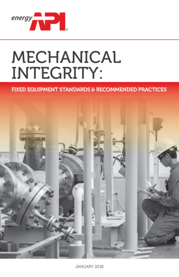
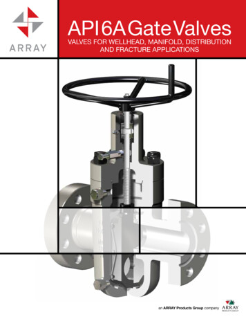
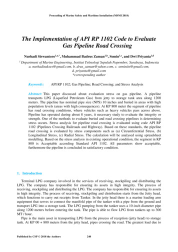
the crossing when the heavy vehicle passes over. The heavy equipment that passes over the pipe isKomatsu PC-200 type with loads greater than 20 tons.To ensure the integrity of the LPG pipeline that has been operating for 8 years, it is necessary toevaluate the strength of the pipeline. Pipe stress analysis is the most important method forconvincing and numerically determining that piping systems in engineering are safe, or a method ofstress calculation on pipes caused by static loads and dynamic loads that are the resultant effects ofgravity, temperature change, pressure inside and outside the pipe, changes in the amount of fluiddischarge flowing in the pipe and the effect of seismic forces [1].API RP 1102 Steel Pipeline Crossing Railroad and Highways is one of the methods / standardsto evaluate the strength of pipes that have undergone road crossing. In this standard, pipe will beevaluated based on longitudinal stress, circumference stress / Hoop stress, and radial stress [2].Figure 1: (a) Burried pipeline and before road crossing ; (b) Pipeline arrise after buried2. MethodologyIn evaluating the strength of the pipe, inspection is required to obtain the data for consideration inthe calculation. Here are some documentation: Complete design and fabricarion drawing / as buid drawing. Manufacture data. Inspection Report. History records. A sketch showing the location of the thickness measurement. All records and repair performed along with procedures and test records.Can be seen in Figure. 2, it shows flowchart methodology API calculation RP 1102. Based on theAPI 1102 standard, the road crossing pipeline is evaluated with concern to longitudinal stress,circumference stress / Hoop stress, and radial stress. Here are the stress components calculated onthe road crossing pipeline:a. Circumferential StressCircumferential Stress is affected by the following components: Circumferential stress due to earth load𝑆𝐻𝑒 𝐾𝐻𝑒 𝐵𝑒 𝐸𝑒 𝛾𝐷Where,𝑆𝐻𝑒𝐾𝐻𝑒 Circumferential stress due to earth loadStiffness factor for circumferential stress from earth load241(1)
𝐵𝑒𝐸𝑒 𝛾𝐷 Burial factor for earth load circumferential stressExcavation factor for earth load Soil unit weight Pipe outside diameterBeginPipe data, operational,installation condition,and site characteristicsInternal LoadExternal LoadEarth loadCalculate circumferencestress due to earth load(Equation 1)Live loadCalcuate wheel load, wand impact factor, Fi(Figure 4)Calculate cycliccircumference stressdue to live load(Equation 2)Calculate cycliclongitudinal stress dueto live load(Equation 5)Calculate circumference stressdue to internal pressure(Equation 3)Calculate circumference stressdue to internal pressure usingBarlow formua.(Equation 9)Shi BarlowallowableFailsPassCalculate the principal stresses,S1, S2, S3(Equation 4, 6, 7)Calculate effective stresses, Seff(Equation 8)FailsCheck for allowable Seff(Equation 11)PassFailsCheck for fatigue(Equation 12, 13)PassSatisfactory designEndFigure. 2: Flowchart stress analysis pipeline road crossing based on API RP 1102242
Circumferential stress due to internal pressure𝑆𝐻𝑖 Where,𝑆𝐻𝑖𝑝𝐷𝑡𝑤 𝑝(𝐷 𝑡𝑤 )2𝑡𝑤 Circumferential stress due to internal pressure Maximum operating pressure Pipe outside diameterWall thicknessMaximum circumferential stress𝑆1 𝑆𝐻𝑒 𝑆𝐻 𝑆𝐻𝑖b.(3)(4)Longitudinal StressLongitudinal Stress is affected by the following components: Longitudinal stress due to highway vehicular load 𝑆𝐿𝑘 𝐾𝐿𝑘 𝐺𝐿𝑘 𝑅 𝐿 𝐹𝑖 𝑤Where, SLkK LkGLkRLFiw Longitudinal stress due to highway vehicular loadHighway stiffness factor for cyclic longitudinal stressHighway geometry factor for cyclic longitudinal stressHighway pavement type factorHighway axle configuration factorImpact factorApplied design surface pressure𝑆2 𝑆𝐿 𝐸𝑠 𝛼 𝑇 (𝑇2 𝑇1 ) 𝑉𝑠 (𝑆𝐻𝑒 𝑆𝐻𝑖 )where, 𝑒𝑆𝐻𝑖 (5)(6)Longitudinal stress due to highway vehicular loadYoung's modulus of steelCoefficient of thermal expansion of steelMaximum or minimum operating temperatureTemperature at time of installationPoisson ratio of steelCircumferential stress due to earth loadCircumferential stress due to internal pressurec. Radial StressRadial Stress is affected by internal pressure.𝑆 𝑃243(7)
Where,𝑆 𝑃 Radial stressMOP (Maximum Operating Pressure)3. Result and Discussion3.1.Pipe DataThe basic technical data of pipes from jetty head to storage tank are as follows:a. Service: LPGb. Material/Schedule: API 5L Gr.B/Sch 40c. SMYS: 35000 psid. Nominal Diameter: 10 inchese. Outside Diameter: 10.75 inchesf. Inside Diameter: 10.02 inchesg. Thickness Nominal: 0.365 inchesh. Type Joint: ERWi. Operating Pressure: 130 psij. Operating Temperature: 24.8 - 77 oFk. Valve rating: 300#l. flange rating: 300#m. Design Factor: 0.5 (Class Location 3)3.2.Stress Calculation1. Area condition of pipeline road crossingThe soil condition in the road crossing area is soft to medium clay category, and loose sand andgravel. The pipeline is located in an area with a density of 46 buildings and industrial, and asaccording to ASME B31.8 belongs to Class Location category 3 [3,5,6]. Maximum vehicle loadreceived by pipe is Komatsu PC-200 with load more than 20 tons. Pipe buried with a depth of 2.7meters. The specifications of Komatsu PC-200 can be seen in Figure. 3.Figure 3: (a) (b) The specification of Komatsu PC-200244
2. Wheel loadWheel loads by ground-contact Komatsu PC-200 at a depth of 2.7 meters shall be correlatedwith Impact Factor values. Impact Factor for highways 1 – 1.5 and decreased 0.03 per ft (0.1 per m)to depths below 5ft (1.5 m). Because of the burried pipe depth of 2.7 m, the impact factor 1.4. Theimpact factor graph can be seen in Figure 4.Figure 4: Recommended impact factor versus depthFor Komatsu PC-Bego 200 used the value of impact factor of 1.4, it becomes the size of wheelloads is 6.97 lb/in2.3. Circumference stressCircumference stress is caused by earth load, vehicular load, and internal pressure. Thecircumference stress calculation uses (1), (2), and (3). Earth LoadTable 1 is the summary calculation on circumference due to earth load (SHe) based on (1).Table 1: Summary Calculation Circumference due to Earth Load𝑲𝑯𝜽800 𝑩𝜽𝑬𝜽1.31D 3(lb/in ) (inch)0.06910.75𝑺𝑯𝜽(psi)771.42Vehicular LoadTable 2 is a summary of calculations on circumference due to vehicular load (SHh) based on(2).245
Table 2: Summary Calculation Circumference due to Vehicular Load𝑲𝑯𝒌 𝑮𝑯𝒌11 RL𝑭𝒊0.85 1.111.4W(lb/in2)6.97 𝑺𝑯𝒌(psi)100.39Internal PressureTable 3 is summary calculation on circumference due to internal pressure (S Hi) based on (3).Table 3: Summary Calculation Circumference due to Internal si)1849.38Total of circumference stress is sum of earth load, vehicular load and internal pressure.From the calculation, total of circumference stress is 2721.19 psi.4. Longitudinal stressLongitudinal stress, caused by vehicular load. The calculation of longitudinal stress using (5).After calculating the longitudinal load due to vehicular load, then maximum longitudinal stress maybe used in the (6). Table 4 is summary calculation on longitudinal stress.Table 4: Summary of Calculation of Maximum Longitudinal Stressw 𝑺𝑳𝒌𝑲𝑳𝒌 𝑮𝑳𝒌 RL𝑭𝒊 (lb/in2) (psi)10.5 11.111.46.97112.74The maximum of longitudinal stress from calculation based on (6) is 2339 psi5. Radial stressRadial stress, caused by internal pressure. By the data of pipe, the maximum operating pressure(MOP) is 130 psi. So, the radial stress is equivalent with the MOP -130 psi.6. Effective stressAfter the total of maximum stress, the next step is continued to calculate total effective stressfrom (8).S eff 1(S1 S 2 )2 (S 2 S3 )2 (S3 S1 )22 (8)Where,S1 Maximum circumferential stress, psiS2 Maximum longitudinal stress, psiS3 Maximum radial stress, psiFrom this formula, total effective stress (Seff) is 2681 psi.7. Check for calculation stressFrom previous calculation, the next steps are checked for the maximum stress based on BarlowFormula and Effective Stress.246
First check for circumferential stress (Barlow formula)Checking for the safety at internal pressurization is accomplished by assuring that thecircumferential stress due to internal pressure calculated by Barlow formula is less than the factoredspecified minimum yield strength [3,4]. Barlow stress formula is shown in (9).SHi (Barlow) pD/2tw(9)The calculation of SHi (Barlow) is 1914 psi. Stress level is acceptable if:SHi (Barlow) F x E x T x SMYSWhere,FETSMYS(10) Design factor Longitudinal joint factor Temperature derating factor Specified minimum yield strengthFrom this calculation of F x E x T x SMYS 17500 psi. Since SHi (Barlow) less than 17500psi, then SHi (Barlow) is Acceptable. Second check for total effective stressThe check against yielding of the pipeline is accomplished by assuring that the total effectivestress is less than the factored specified minimum yield strength.The calculation of total effective stress is 2681 psi. Stress level is acceptable if:Seff F x SMYS(11)From this calculation of F x SMYS 17500 psi. Since Seff less than 17500 psi, then Seff isAcceptable.8. Check for fatigueThe check for fatigue is accomplished by comparing a stress component normal to weld in thepipeline againts an allowable value of this stress, referred to as a fatigue endurance limit. First check for potential fatigue in girth weldThe cyclic stress that must be checked for potential fatigue in a girth weld located beneath aroadcrossing is the longitudinal stress due to live load. The design check is accomplished by asuringthat the live load cyclic longitudinal stress is less than the factored fatigue endurance limit. Thegirth weld check is given by the following SLh SFG x F(12)From this calculation of SFG x F 6000 psi, and SLh from Table 4 is 112.74 psi. Since SLhless than 6000 psi, then potential fatigue in girth weld is Acceptable.247
Second check for potential fatigue in longitudinal weldThe cyclic stress that must be checked for potential fatigue in a girth weld located beneath aroadcrossing is the circumferential stress due to live load. The design check is a accomplished byasuring that the live load cyclic circumferential stress is less than the factored fatigue endurancelimit. The longitudinal weld check is given by the following SHh SFL x F(13)From this calculation of SFL x F 10500 psi, and SHh from Table II is 100.39 psi. Since SHhless than 10500 psi, then potential fatigue in longitudinal weld is Acceptable.4. ConclusionsThe Pipeline transports LPG from jetty to storage tank area along 1200 meters. The pipeline hasnominal pipe size (NPS) 10 inches and buried in areas with high population levels (areas with highconsequences). At KP 800 meter the segment of pipeline has road crossing conditions. Based on thestress analysis in existing operational condition, the segment in KP 00 800 is Acceptableaccording Standard API 1102. From the calculation and checking all parameters the segment in KP00 800 is Acceptable by checked for four parameters: Acceptable by checked circumference stress (Barlow Stress), Acceptable by checked total effective stress, Acceptable by checked potential fatigue in girth weld, Acceptable by checked potential fatigue in long
API RP 1102 Steel Pipeline Crossing Railroad and Highways is one of the methods / standards to evaluate the strength of pipes that have undergone road crossing. In this standard, pipe will be evaluated based on longitudinal stress, circumference stress / Hoop stress, and radial stress [2]. Figure 1: (a) Burried pipeline and before road crossing ; (b) Pipeline arrise after buried 2. Methodology .
![API Ballot: [Ballot ID] – API 510 & API 570, Deferrals, Rev05](/img/5/api510andapi570deferralsrev5.jpg)