Transcription
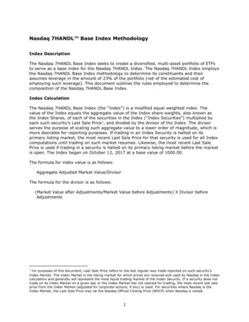
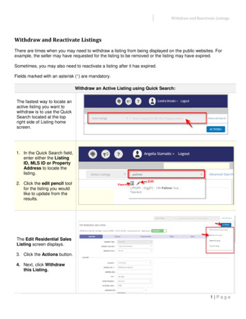
WHi Listing IndexConstruction JointsClassMovement 33.025.012.5IFCEFC JWA/PH 120-03 Hourly Rating11&22211&21&24SteelEIFSStone VeneerFramingBrick VeneerAluminum PanelsConcrete PanelsGlassSteelCurtain WallTilt-Up PanelsWall ExteriorEFS Stud AluminumN/AHOURLYJWA/PHV 60-01JWA/PHV 120-03JWA/PHV 120-04JWA/PHV 120-07JWA/PV 60-02JWA/PV 120-04JWA/PV 120-05JWA/PV 240-01GrabberGard ProductsMax Joint WidthWall to WallHead of WallFloor to WallFloor to FloorJoint SystemsBottom of WallJoints2Page 1 of 1November 2003
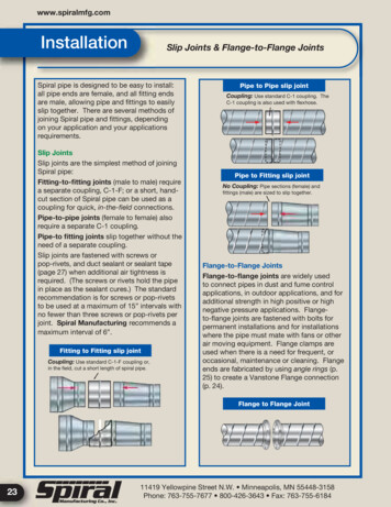
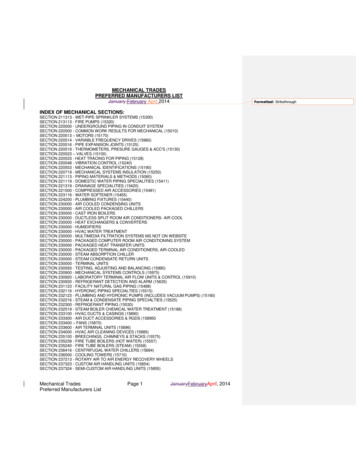
John Wagner & Associates Inc.dba GRABBER CONSTRUCTION PRODUCTS205 Mason Circle, Concord, CA, 94520GrabberGard EFSDesign No. JWA/PH 120-03Horizontal or Vertical Expansion/Control JointsTest Standards: ASTM E-119, ULC S115-M95L-Rating At Ambient 1 CFM/Lin FtL-Rating At 400 F 1 CFM/Lin FtTest Furnace Internal Positive Pressure Differential – 2.5 Pa (0.01 in. of water) MinimumPenetratingMaterial & SizeHorizontal JointsMaxFireTemp.Width10""F" Ratingup to 2hrs"FT" Rating30 minSystem Design Instructions1.Floor/Ceiling Assemblies: ASTM E-119 and CAN/ULC S101 up to 2 hour rated floor/ceilingassemblies; Cast in place normal or light density concrete floor/ceiling assemblies having a minimumcross section thickness of 4-1/2in. (114mm) and including the following:A.Steel Angle – Perimeter of floor assembly to be provide with min 1-1/2 by 1-1/2 by 3/16 in. thickcast-in-place structural steel angle for weld-attachment of EIFS mounting attachment (Item 2E).
John Wagner & Associates Inc.dba GRABBER CONSTRUCTION PRODUCTS205 Mason Circle, Concord, CA, 94520GrabberGard EFSJWA/PH 120-032.Exterior Insulation Finish System: This Exterior Insulation Finish System (EIFS) to be constructed ofthe materials and in the manner described by the EIFS wall manufacturer’s installation instructions andshall include the following features:A.Cementitious Finish Coating – Min 1/16 in. thick cementitious finish coating applied as perEIFS wall manufacturer’s instructions.B.Expanded Polystyrene (EPS) Foam Boards – Max 3 in. thickness of expanded polystyrenefoam boards applied to exterior gypsum board as per EIFS wall manufacturer’s instructions.C.Exterior Gypsum Board – Min 1/2 in. thick exterior gypsum boards applied to steel studs withmin 1 in. long pan head screws at 10 OC. Gypsum boards installed as per EIFS wallmanufacturer’s instructions.D.Steel Stud Framing – Vertical framing members shall be min 3-5/8 in. by 1-1/4 in., 16 ga steel“C” studs. Attachment shall be according to EIFS wall manufacturer’s guidelines.Verticalframing shall not exceed a spacing of 24 in. OC.E.Mounting Attachment – Min 1-1/2 in. by 1-1/2 in. by 3/16 in. thick structural steel angle weldattached to steel stud framing and cast-in-place structural angle located max 48 in. OC.F.Impaling Pins – Min 6-1/2 in. long 12 ga steel pins, welded or mechanically fastened to flat sideof steel studs and bent 90 degrees perpendicular to the face of the curtain wall insulation. Pins tobe installed at max 8 in. OC vertically and at max 24 in. OC horizontally.G.Curtain Wall Insulation – Min 4 in. 4 pcf mineral wool board, unfaced or faced on one side withaluminum foil/scrim vapor retarder, supplied in min 24 in. wide boards. Mineral wool board to beimpaled on pins, flush with interior surface of steel studs, and secured in position with min 1-1/4in. square steel clinch shields. Fill the cavity of all “C” shaped studs with insulation. A singlepiece of 24 in. wide mineral wool to extend a min 12 in. below and min 8 in. above the of thebottom and top surfaces of the concrete floor assembly.3.Firestop System Component 1: Steel angle manufactured from min 16 ga steel to be welded ormechanically fastened to vertical steel studs. Angle to be installed such that the horizontal leg of angleis min 4 in. below the top surface of the concrete floor assembly to support the mineral wool insulation(Item 4). Size and installation of steel angle is as follows:A.Joints ranging from 0 to max 2 in. – No angle is required.B.Joints ranging from min 2 to max 6 in. – Min 1 by 1 in. angle to be installed.C.Joints ranging from min 6 to max 10 in. – Min 1 by 3 in. angle to be installed such that the 3in. leg is installed horizontally with the 1 in. leg installed vertically.4.Firestop System Component 2: Filler material mineral rock wool or ceramic fiber insulation with a3minimum density of 4-6 PCF (68 kg/m ) with mineral wool fibers running perpendicular to curtain walland compressed a minimum of 20% into the joint space at a minimum depth of 4 in. (102 mm). As analternative, the min 4 pcf mineral wool maybe installed such that the mineral wool fibers run parallel tocurtain wall and are compressed a minimum of 40% into the joint space at a minimum depth of 4in.(102 mm).5.Firestop System Component 3: John Wagner & Assoc. Inc. dba GRABBER CONSRTUCTIONPRODUCTS – GrabberGard EFS* (mastic) for horizontal applications sprayed into place with aminimum wet film thickness of 3/32 in. (2.5 mm). Always overlap GrabberGard EFS* onto the surfaceof the substrate a minimum of 1in. (25 mm). Do not thin GrabberGard EFS* firestop mastic whenspraying, use equipment capable of applying material as supplied.*WH Labeled Component
John Wagner & Associates Inc.dba GRABBER CONSTRUCTION PRODUCTS205 Mason Circle, Concord, CA, 94520GrabberGard EFSDesign No. JWA/PHV 60-01Metal Decking to Vertical Wall AssembliesTest Standards: UL 2079 Rating: 1 hour “F”Test Standards: ULC S115-M95 Rating: 1 hour “FTH”Test Furnace Internal Positive Pressure Differential – 2.5 Pa (0.01 in. of water) MinimumJoint System Cycled 500 Times at 10 cycles per Minute – 25% Compression or ExtensionSystem Design Instructions1.Floor/Ceiling Assembly: 1 hour ASTM E-119 or CAN/ULC S101 fluted steel deck roof/ceiling or floor/ceiling assemblies.A.Steel Deck: Galvanized steel fluted units.B.Concrete: Min. 2-1/2” (63mm) deep concrete, as measured from the top plane of the steel deck (1A).2.Wall Assembly: 1 hour ASTM E-119 or ULC S101 metal framed gypsum wallboard (GWB) wall assemblies and shall include thefollowing:A.Ceiling Runner & Deflection Channel: 3-5/8” (91mm) x 1-1/2” (38mm) U-shaped runner with optional min. 24 Ga. withmin. 2” (50mm) deep legs U-shaped deflection channel. When deflection channel is used, ceiling runner is installed withinthe deflection channel maintaining a 3/4” (19mm) gap between the top of the ceiling runner and top of the deflectionchannel and deflection channel is attached to floor/ceiling assembly. When deflection channel is not used ceiling runneris fastened directly to floor/ceiling assembly with steel fasteners or by welds spaced max. 24” (600mm) OC.A1.Slotted Ceiling Runner: (As an alternative to 2A) 3-5/8” (91mm) U-shaped runner with slotted flanges, fastened tofloor/ceiling assembly.B.Studs: 3-5/8” (91mm) wide ‘C’ studs, spaced 24” (600mm), cut 1/2” (13mm) to 3/4” (19mm) less in length than assemblyheight.C.Wallboard*: 5/8” (16mm) Type X gypsum wallboard, straight cut 3/4” (19mm) below lower surface of floor/ceilingassembly.The hourly F Rating of the firestop system is equal to the hourly fire rating of the wall assembly in which it is installed.3.Firestop System, Component 1: Filler material- Min. 2 in. (50 mm) thick min. 4 PCF (64kg/m3) density mineral wool insulationcompressed min. 25% between the top track and the underside of the top of the flute. Additional pieces of min. 5/8 in. (19 mm)thickness of min. 4 PCF (64kg/m3) density mineral wool insulation compressed min. 25% between the top of the gypsumwallboard and the underside of steel deck. Filler material to be flush with both sides of wall assembly.4.Firestop System, Component 2: Min. 1/16” (60mil) dry thickness of John Wagner & Assoc. Inc. dba GRABBERCONSRTUCTION PRODUCTS – GrabberGard EFS* sprayed or brushed on each side of the wall assembly, fully covering allfiller material and overlapping a min of 1” (25mm) onto the metal deck and wall assembly.*WH Labeled Component
John Wagner & Associates Inc.dba GRABBER CONSTRUCTION PRODUCTS205 Mason Circle, Concord, CA, 94520GrabberGard EFSGrabberGard EFCGrabberGard IFCDesign No. JWA/PHV 120-03Metal Decking to Vertical Wall AssembliesRating: Up to 2 Hours "FTH"Test Standards: ASTM E-814, UL 2079, ULC S115-M95Test Furnace Internal Positive Pressure Differential – 2.5 Pa (0.01 in. of water) MinimumMax Joint Width at Top of Wall – 3/4” (19 mm)Joint System Cycled 500 Times at 10 Cycles Per Minute – 33% Compression or ExtensionSystem Design Instructions1. Penetrating Item: Steel beam or open-web steel joist, as specified in the individual roof/ceiling orfloor/ceiling design, used to support fluted steel deck. Structural steel support oriented perpendicular towall assembly. Where open-web steel joist pass through the fire rated wall, 3/8 in. diamond meshexpanded steel lath having a nom weight of 1.7 to 3.4 lbs per sq yd shall be secured to one side of eachjoist with galvanized steel tie wire and the lath shall be fully covered with spray-applied fire resistivematerial applied in accordance with the specifications in the individual roof/ceiling or floor/ceiling design.The clearance between the top of the gypsum board and the bottom of the spray-applied structural steelmember to be 0" to max 3/4" (19 mm).2. Roof/Ceiling of Floor/Ceiling Fire Separation: 1 or 2 hour ASTM E-119 or CAN/ULC S101 fluted steeldeck (GWB) roof/ceiling or floor/ceiling assemblies.Wall Fire Separation: 1 or 2 hour ASTM E-119 or CAN/ULC S101 metal framed gypsum wall board (GWB)wall assemblies consisting of a single or a double top track consisting of a single top track with a deflectionchannel or slip track.The hourly rating of the joint system is equal to the lesser hourly rating of either theroof/floor/ceiling or the wall assembly.3. Firestop System, Component 1: Filler material, Min 4-6 PCF (68 kg/m3) density mineral wool insulationat a min depth of 6-1/8" (157mm) compressed into each flute opening in the steel deck and into the framedbeam opening in the wall assembly flush with both sides of the wall assembly.4. Firestop System, Component 2: Cafco 300 or WR Grace Type MK-6/HY applied to the underside of theroof/ceiling or floor/ceiling assembly and all surfaces of the structural steel support. Spray-applied inaccordance with the specifications in the individual roof/ceiling or floor/ceiling design.5. Firestop System, Component 3:Method 1: Spray or Brush: One heavy coat of John Wagner & Assoc. Inc. dba GRABBERCONSTRUCTION PRODUCTS – GrabberGard EFS*, 1/16" (63 mil) dry thickness, on both sides of theassembly, fully covering all voids and overlapping a minimum of 1" (25mm) onto the metal deck, steelbeam and wall assembly.Method 2: Caulk: Min 1/8” (3 mm) thickness of John Wagner & Assoc. Inc. dba GRABBERCONSTRUCTION PRODUCTS – GrabberGard EFC* or GrabberGard IFC*, applied between thegypsum wall board and spray applied fire resistance material on both sides of the assembly, fullycovering all voids, and overlapping a minimum of 1/8” (3 mm) onto the metal deck, steel beam and wallassembly.*WH Labeled ComponentFL05/06(NJ)
John Wagner & Associates Inc.dba GRABBER CONSTRUCTION PRODUCTS205 Mason Circle, Concord, CA, 94520GrabberGard EFCGrabberGard IFCGrabberGard EFSDesign No. JWA/PHV 120-04**Fire Rated Non-Flammable Acoustic Firestop SealantHorizontal or Vertical (floor/ceiling and walls)Test Standards: ASTM E-814, UL 1479, ULC S115-M95Test Furnace Internal Positive Pressure Differential – 2.5 Pa (0.01 in. of water) MinimumASTM E-814“F” Rating “T” Rating2 Hour2 HourULC S115“FTH” Rating2 HourSystem Design Instructions1.2.3.4.Penetrating Item: Not applicable.Floor/Ceiling or Wall Fire Separations: 1 and 2 hour rated ASTM E-119 or CAN/ULC S101 concrete,metal or wood framed fire rated gypsum wall board (GWB) floor/ceiling/wall assemblies.Firestop System Component 1: John Wagner & Assoc. Inc. dba GRABBER CONSTRUCTIONPRODUCTS – GrabberGard EFC* or GrabberGard IFC* firestop sealant at a minimum bead diameter of3/8" (10mm) caulked into the corner and behind the GWB around the entire perimeter of the fire rated wallassembly. Attach gypsum wall board (GWB) membranes into the sealant within 15 min of sealantplacement or prior to sealant skinning.Firestop System Component 2: Filler material not required.Optional - When max separation between bottom of ceiling membrane and wall membrane is less than 1/16of an inch.5. Firestop System Component 3: John Wagner & Assoc. Inc. dba GRABBER CONSTRUCTIONPRODUCTS – GrabberGard EFS* firestop spray applied a minimum dry thickness of 1/16” (2mm)sprayed into the corner and behind the GWB around the entire perimeter of the fire rated wall assembly.Attach gypsum wall board (GWB) membranes into the sealant within 15 min of sealant placement or priorto sealant skinning*WH Labeled Component**The acoustic claims have not been verified by Intertek Testing Services
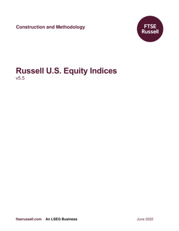
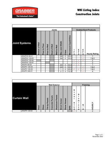
John Wagner & Associates Inc.dba GRABBER CONSTRUCTION PRODUCTS205 Mason Circle, Concord, CA, 94520GrabberGard EFCGrabberGard IFCDesign No. JWA/PHV 120-07Horizontal or Vertical Static Stair JointsTest Standards: UL 2079, ULC S115-M95Test Furnace Internal Positive Pressure Differential – 2.5 Pa (0.01 in. of water) MinimumConfiguration 1PenetratingMaterial & SizeVertical and Horizontal JointsMaxUL 2079ULC S115-M95Width2""F" Ratingup to 2hrs"FTH" Ratingup to 2hrsMaxUL 2079ULC S115-M95Width1/2""F" Ratingup to 2hrs"FTH" Ratingup to 2hrsConfiguration 2PenetratingMaterial & SizeVertical and Horizontal Joints
John Wagner & Associates Inc.dba GRABBER CONSTRUCTION PRODUCTS205 Mason Circle, Concord, CA, 94520GrabberGard EFCGrabberGard IFCJWA/PHV 120-07System Design Instructions1. Wall Assemblies: ASTM E-119 and CAN/ULC S101 up to 2 hour fire rated wallassemblies as follows:a) Cast in place concrete wall assemblies having a minimum cross section thickness of 5"(125mm) or;b) Hollow or concrete filled unit masonry (concrete block) wall assemblies laid up withmortar having a minimum cross section thickness of 8" (200mm).2. Concrete Stair Assemblies: Min 2 hour fire-rated concrete stair assembly having a minthickness of 6-1/2 in.Configuration 13. Firestop System Component 1: Filler material mineral rock wool or ceramic fiber3insulation with a minimum density of 4-6 PCF (68 kg/m ) compressed a minimum of 25%into the joint space at a minimum depth of 5” (120 mm). Recess filler material toaccommodate for grout (Item 4) placement on top side of staircase. Recess filler materialto accommodate sealant placement (Item 5) placement on underside of staircase.4. Firestop System Component 2: Min. 1” (25 mm) thick cementitious grout installed intojoint on topside of staircase assembly.5. Firestop System Component 3: John Wagner & Assoc. Inc. dba GRABBERCONSTRUCTION PRODUCTS – GrabberGard EFC* or GrabberGard IFC* for vertical orhorizontal applications installed at a minimum thickness of 1/2 in (12mm) into joint onunderside of staircase assembly.Configuration 26. Firestop System Component 1: John Wagner & Assoc. Inc. dba GRABBERCONSTRUCTION PRODUCTS – GrabberGard EFC* or GrabberGard IFC* for vertical orhorizontal applications installed at a minimum thickness of 1/2 in (12mm) into joint on topand underside of staircase assembly.*WH Labeled Component
John Wagner & Associates Inc.dba GRABBER CONSTRUCTION PRODUCTS205 Mason Circle, Concord, CA, 94520GrabberGard EFCGrabberGard IFCDesign No. JWA/PV 60-02Metal Decking to Vertical Wall AssembliesRating: Up to 1 Hour “FTH”Test Standards: ULC S115-M95Rating: Up to 1 Hour "F Rating"Test Standards: ASTM E-814, UL 2079Test Furnace Internal Positive Pressure Differential – 2.5 Pa (0.01 in. of water) MinimumJoint System Cycled 500 Times at 10 Cycles Per Minute – 33% Compression or ExtensionSystem Design Instructions1. Floor/Ceiling Fire Separation: 1 or 2 hour ASTM E-119 or CAN/ULC S101 fluted steel deck roof/ceiling orfloor/ceiling assemblies.Wall Fire Separation: 1 hour ASTM E-119 or ULC S101 metal framed gypsum wallboard (GWB) wallassemblies with a single slip track ceiling runner or a double top track system consisting of a single top trackwith a deflection channel. Gypsum board cut to profile of coated fluted steel deck with a nominal 3/4 in.(19mm) joint between the top of the gypsum board and the underside of the spray applied fire resistivematerial. Steel studs to be cut 1/2 to 3/4 in. less than assembly height.2. Firestop System Component 1: Min 3/8 in. to max 15/16 in. thickness of MK-6 spray applied fire resistivematerial applied to the underside of the floor/ceiling assembly.3. Firestop System Component 2: John Wagner & Assoc. Inc. dba GRABBER CONSTRUCTION PRODUCTS– GrabberGard EFC* or GrabberGard IFC* into the gap between the top of the gypsum wallboard and thespray applied fire resistive material to the full depth of the gypsum board membrane on both sides of the wallassembly.*WH Labeled Component
John Wagner & Associates Inc.dba GRABBER CONSTRUCTION PRODUCTS205 Mason Circle, Concord, CA, 94520GrabberGard IFCDesign No. JWA/PV 120-03Single PenetrationsVertical (walls)Test Standards: ASTM E-814, UL 1479: open and closed system, ULC S115-M95: closed systemsPositive Pressure Differential – 2.5 Pa (0.01 in. of water) MinimumPenetratingMaterial & SizeMaxHole SizeAnnularSpaceE 814 &“F” RatingUL 1479“T” RatingS115-M95“F” RatingPVC Plastic pipe to 2”CcPVC Plastic pipe to 2”CPVC Plastic pipe to 2”CPVC Plastic pipe to 2”X-Linked Polyethylene tubing to 1” IDX-Linked Polyethylene tubing to 1” 4”1/2”1/2”0 Hr0 HrUp to 2 Hr0 Hr0 HrUp to 2HrUp to 40 minUp to 40 minUp to 20 minUp to 115 minUp to 70 minUp to 15 minUp to 2 HrUp to 2 HrUp to 2 HrUp to 2 HrUp to 2 HrUp to 2HrFire/Hose“FH”Rating0 Hr0 HrUp to 2 Hr0 Hr0 HrUp to 2HrTemp Rating“FTH”RatingUp to 40 minUp to 40 minUp to 20 minUp to 115 minUp to 70 minUp to 15 minSystem Design Instructions1. Penetrating Item: Centered in hole, see table above.2. Wall Fire Separations: 2 hour rated ASTM E-119 or CAN/ULC S101 metal or wood framed insulatedgypsum wall board (GWB) wall assemblies.3. Firestop System; Component 1: One layer of 5/8” Type “X” gypsum wallboard collar securely fastened togypsum wallboard with drywall anchors. Caulk a 3/8” (10mm) bead around perimeter edges of GWB collarafter installation.4. Firestop System; Component 2: John Wagner & Assoc. Inc. dba GRABBER CONSTRUCTIONPRODUCTS – GrabberGard IFC* fully filling the annular space to the full depth of the membrane.*WH Labeled Component
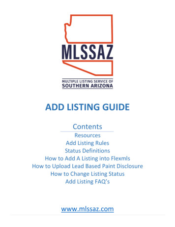
John Wagner & Associates Inc.dba GRABBER CONSTRUCTION PRODUCTS205 Mason Circle, Concord, CA, 94520GrabberGard EFSDesign No. JWA/PV 120-04Metal Decking to Vertical Wall AssembliesRating: Up to 2 Hours "FTH"Test Standards: ASTM E-814, UL 2079, ULC S115-M95Test Furnace Internal Positive Pressure Differential – 2.5 Pa (0.01 in. of water) MinimumJoint System Cycled 500 Times at 10 Cycles Per Minute – 33% Compression or ExtensionMethod 1Method 2System Design Instructions1. Floor/Ceiling Fire Separation: 1 or 2 hour ASTM E-119 or CAN/ULC S101 fluted steel deck (GWB)roof/ceiling or floor/ceiling assemblies.Wall Fire Separation: 1 or 2 hour ASTM E-119 or ULC S101 metal framed gypsum wall board (GWB) wallassemblies with a double top track consisting of a single top track with a deflection channel or slip track.The hourly F Rating of the firestop system is equal to the hourly fire rating of the wall assembly inwhich it is installed.2. Firestop System, Component 1:Method 1: Filler material, 4 pcf mineral wool or 2.5 pcf fiberglass insulation compressed into each fluteopening in the steel deck as a backing material for the Cafco 300.Method 2: Filler material, Cafco 300 applied into each flute opening in the steel deck.3. Firestop System, Component 2: Min 3/8" to max 15/16" thickness of Cafco 300 applied to the undersideof the floor/ceiling assembly with a 3" diameter radius formed at the steel deck/wall board interface on bothsides of the wall assembly.4. Firestop System, Component 3: Spray or brush one heavy coat of John Wagner & Assoc. Inc. dbaGRABBER CONSTRUCTION PRODUCTS – GrabberGard EFS*, 1/8" (3mil) thick, on both sides of theassembly, fully covering all voids and overlapping a minimum of 1" (25mm) onto the metal deck and wallassembly.*WH Labeled Component
John Wagner & Associates Inc.dba GRABBER CONSTRUCTION PRODUCTS205 Mason Circle, Concord, CA, 94520GrabberGard EFCGrabberGard IFCGrabberGard EFSDesign No. JWA/PV 120-05Metal Decking to Vertical Wall AssembliesRating: Up to 2 Hours “FTH”Test Standards: ASTM E-814, UL 1479, ULC S115-M95Test Furnace Internal Positive Pressure Differential – 2.5 Pa (0.01 in. of water) MinimumMax Joint Width – 1in.Joint System Cycled 500 Times at 10 Cycles Per Minute – 25% Compression or ExtensionSystem Design Instructions1. Steel Decking: Minimum 22 gauge or equal galvanized steel decking with up to 3½" (88mm) flute heightfirmly supported, with or without concrete cover.2. Floor/Ceiling Fire Separations:a)1 and 2 hour ASTM E-119 or CAN/ULC S101 fluted steel deck roof/ceiling or floor/ceilingassemblies.3. Wall Fire Separations Terminating at Fluted Steel Deck:a)1 and 2 hour ASTM E-119 or CAN/ULC S101 metal or wood framed gypsum wall board (GWB)assemblies or;b)Cast in place normal or light density concrete floor/ceiling assemblies having a minimum crosssection thickness of 4½" (114mm) or;c)Cast in place concrete wall assemblies having a minimum cross section thickness of 6" (150mm) or;d)Hollow or concrete filled unit masonry (concrete block) wall assemblies laid up with mortar having aminimum cross section thickness of 8" (200mm).
John Wagner & Associates Inc.dba GRABBER CONSTRUCTION PRODUCTS205 Mason Circle, Concord, CA, 94520GrabberGard EFCGrabberGard IFCGrabberGard EFSJWA/PV 120-054. Firestop System Component 1:Method 1: Dip & Brush: Dip each insert individually and fully coat in GrabberGard EFS* (firestop mastic),insert into flute opening to the desired depth. Brush exposed surface of insert on both sides smoothoverlapping ½" (13mm) onto metal decking and/or the wall assembly to ensure complete coverage and nosmall gaps or pin holes exist. Brush excess material between flute foot and deflection/slip track to the nextopen flute cavity, sealing the seam between the steel decking and the deflection/slip track. If larger spacesare evident, fill tightly with mineral wool and brush a 1/16" (60mil) coat of GrabberGard EFS* to fully coverthe area.Method 2: Spray or Brush: Install each insert at the desired location and spray or brush one heavy coat ofGrabberGard EFS* 1/8" (120mil) thick, on both sides of the assembly, fully covering all voids andoverlapping a minimum of ½"(13mm) onto the metal deck and wall assemblyMethod 3: Caulk to profile: Cut the gypsum wallboard to the profile of the deck and install to within ¾" ofthe deck. Caulk GrabberGard EFC* or GrabberGard IFC* into the gap between the gypsum board and thedeck to the depth of the gypsum board membrane.5. Firestop System Component 2: Flute Opening: Insert of 4-6 PCF (68kg/m3) mineral wool, cut 10% largerthan the opening area. Depth: Cut the mineral wool insert to a depth of 5" (125mm) for the single insertdetail, for the two-piece detail cut two 2½" deep inserts. Two-piece details can be installed one on eachside of the assembly flush with the membrane surface. Additional pieces of mineral wool batt insulation areto be compressed 33 percent in thickness and are installed to completely fill the gap above the top of thewall and the bottom of the steel floor units, flush with both surfaces of wall. Mineral wool inserts can beinstalled in any of the configurations detailed in Methods 1 and 2. Exception: when flutes are runningparallel with the wall, cut 4-6 PCF (68kg/m3) mineral wool inserts to the desired shape, 10% larger than theopening area and compress into the open cavity. All details require sealant as outlined in Section 3 of thissystem design.6. Firestop System Component 3: (Optional) – When gaps between top of wall and bottom of the steel deckis less than or equal to 3/4 in. – Nom 1 in. diam polyethylene rod compressed and firmly packed into thenom 3/4 in. gap between the top of the wall and the bottom of the steel deck and forming material (Item 5)in areas of fluted deck. Backer rod compressed to be flush with surface of wall.*WH Labeled Component
John Wagner & Associates Inc.dba GRABBER CONSTRUCTION PRODUCTS205 Mason Circle, Concord, CA, 94520GrabberGard EFSDesign No. JWA/PV 240-01Concrete Deck to Vertical Wall AssembliesTest Standards: ASTM E-814, UL 2079, CAN/ULC S115-M95L-Rating At Ambient 1 CFM/Lin FtL-Rating At 400 F 1 CFM/Lin FtTest Furnace Internal Positive Pressure Differential – 2.5 Pa (0.01 in. of water) MinimumMax. Joint Movement – 12.5% Compression or ExtensionUL 2079CAN/ULC S115-M95Max AssemblyFireFire/HoseTemp.Construction Joint WidthRating"F" Rating "FH" Rating "FTH" RatingHorizontal Joints2"4 Hrs4 Hrs4 Hrs4 HrsSystem Design Instructions1. Floor/Ceiling Assemblies: Cast in place normal or light density concrete floor/ceiling assemblies having aminimum cross section thickness of 5" (125 mm)2. Wall Assemblies: ASTM E-119 or CAN/ULC S101 up to 4 hour rated wall assemblies conforming to asfollows:a) Cast in place concrete wall assemblies having a minimum cross section thickness of 6-3/4" (171mm)or;b) Hollow or concrete filled unit masonry (concrete block) wall assemblies laid up with mortar having aminimum cross section thickness of 8" (200mm).3. Firestop System – Component 1 – Filler material mineral rock wool or ceramic fiber insulation with a mindensity of 4 PCF (64 kg/m3) compressed a minimum of 40% into the joint space flush with both sides ofwall assembly.4. Firestop System – Component 2 – John Wagner & Assoc. Inc. dba GRABBER CONSTRUCTIONPRODUCTS – GrabberGard EFS* – Minimum dry film thickness 1/16" (1.5mm) sprayed or brushed intoplace completely covering fillet material and overlapping onto all concrete surface a minimum of 1” (25mm).*WH Labeled Component
Exterior Insulation Finish System: This Exterior Insulation Finish System (EIFS) to be constructed of the materials and in the manner described by the EIFS wall manufacturer's installation instructions and shall include the following features: A. Cementitious Finish Coating - Min 1/16 in. thick cementitious finish coating applied as per