Transcription
The Future of the CAVEAuthors:Thomas A. DeFanti (tdefanti@ucsd.edu)1Daniel Acevedo3Richard A. Ainsworth5Maxine D. Brown2Steven Cutchin3Gregory Dawe1Kai-Uwe Doerr1Andrew Johnson2Chris Knox3Robert Kooima4Falko Kuester1Jason Leigh2Lance Long2Peter Otto1Vid Petrovic1Kevin Ponto1Andrew Prudhomme1Ramesh Rao1Luc Renambot2Daniel J. Sandin2Jurgen P. Schulze1Larry Smarr1Madhu Srinivasan3Philip Weber1Gregory Wickham3Affiliations:1California Institute for Telecommunications and Information Technology (Calit2), University ofCalifornia San Diego (UCSD), San Diego, California, USA2Electronic Visualization Laboratory (EVL), University of Illinois at Chicago (UIC), Chicago,Illinois, USA3King Abdullah University of Science and Technology (KAUST) Visualization Laboratory,Thuwal, Saudi Arabia4Center for Computation & Technology (CCT), Louisiana State University, Baton Rouge,Louisiana, USA5Ainsworth & Partners, Inc., Ridgeway, Wisconsin, rdsThe Classic CAVECAVEs of Today4.A.!Goals and Features4.B.! StarCAVE4.C.! Cornea2!2!2!6!6!7!9!
5.!6.!7.!8.!1.4.D.!NexCAVE4.E.! Design Challenges with Today’s CAVEs4.E.1.! Projector-based CAVE Design Challenges4.E.2.! Panel-based CAVE Design ChallengesCAVEs of the Future: Design Considerations5.A.!OptIPortal Displays5.B.! Active Stereo vs. Passive Stereo5.C.! Autostereo5.D.!REVE (Rapidly Expandable Virtual Environment)5.E.! AESOP (Almost Entirely Seamless OptiPortal)5.F.! Next-Generation CAVE (NG-CAVE)5.G.!Software5.G.1.! CGLX5.G.2.! SAGE5.G.3.! tThe CAVE, a walk-in virtual reality environment typically consisting of 4-6 3m-by-3m sides of aroom made of rear-projected screens, was first conceived and built in 1991. In the nearly twodecades since its conception, the supporting technology has improved so that current CAVEs aremuch brighter, at much higher resolution, and have dramatically improved graphics performance.However, rear-projection-based CAVEs typically must be housed in a 10m3 room (with spacebehind the screen walls for the projectors), which limits their deployment to large spaces. TheCAVE of the future will be made of tessellated panel displays, eliminating the projectiondistance, but the implementation of such displays is challenging. Early multi-tile, panel-based,virtual-reality displays have been designed, prototyped, and built for the King AbdullahUniversity of Science and Technology (KAUST) in Saudi Arabia by researchers at the Universityof California, San Diego, and the University of Illinois at Chicago. New means of imagegeneration and control are considered key contributions to the future viability of the CAVE as avirtual-reality device.2.KeywordsCAVE, Computer-supported collaborative work (CSCW), Graphics packages, Image displays,Immersive environments, Interactive environments, Sonification, Tele-immersion, Virtual reality,Scalable multi-tile displays.3.The Classic CAVEThe “classic” CAVETM [Figure 1][Cruz-Neira92] is a cube-shaped virtual-reality (VR) room,typically 3m-by-3m-by-3m in size, whose walls, floor and sometimes ceiling are entirely made ofcomputer-projected screens. All participants wear active stereo glasses to see and interact 0!30!30!
complex 3D objects. One participant wears a six degree-of-freedom location and orientationsensor called a tracker so that when he/she moves within the CAVE, correct viewer-centeredperspective and surround stereo projections are produced quickly enough to give a strong sense of3D visual immersion.Projection-based VR systems, such as CAVEs, feature surround viewing (ideally fully-surround,but usefully at least 90 in two dimensions such that users do not see the edges of the display).They offer stereo visuals. And, they track the user to provide the correct scene perspectiverendering in a continuous manner. Viewer-centered perspective and surround viewing distinguishVR systems from 3D movies.The classic CAVE was conceived and designed in 1991 by Tom DeFanti and Dan Sandin, who atthe time were professors and co-directors of the Electronic Visualization Laboratory (EVL) at theUniversity of Illinois at Chicago (UIC). Many students and colleagues over the years contributedto CAVE software and hardware development, as seen in this paper’s many references.The goal of room-sized VR is to help scientists and engineers achieve scientific insight, and alsoto create a medium worthy of use by teachers, fine artists, architects, and archaeologists. Themost advanced classic CAVE to date, called Cornea, was installed in mid-2009 at the KingAbdullah University of Science and Technology (KAUST) by Mechdyne Corporation[Mechdyne], and co-located with a new-generation of unique VR systems, designed by a team ledby DeFanti, who is now at the California Institute for Telecommunications and InformationTechnology (Calit2) at University of California, San Diego (UCSD).CAVE participants see projected computer-generated stereo scenes but can also see their armsand bodies and can easily interact with one another. The classic CAVE uses active stereo; therendering computers generate perspective views that are projected onto the walls for the left andright eyes of the primary participant in synchrony with electronic shutter glasses. The activeeyewear is driven transparent in front of the left eye when the left eye image is projected, andopaque otherwise; similarly, the right eye receives the right image. Images need to be generatedat 96Hz (or higher) so each eye gets a flicker-free display. This is the way the new (2010)consumer 3D HDTVs work if they use active shutter glasses. For successful active stereo, allscreens must be synchronized so that each eye sees only the left or right stereo image on everyscreen at the same time, a requirement that is non-trivial as the number of screens and projectorsincreases; therefore, the underlying hardware and drivers must support synchronization.The classic CAVE uses rear-screen projection for the walls so the viewer does not cast shadowson the screens; however, as is often the case, when the floor is projected down from the top, theprojection creates a small shadow around participants’ feet. A CAVE with three walls and a floorminimally requires a 13m-by-10m space with a 4.5m high ceiling. Six-sided CAVEs (likeKAUST’s Cornea and Iowa State’s C-6, as well as others built in Gifu, Stockholm, and Stuttgart,for example) feature rear projection from every direction, requiring doubly higher ceilings andelaborate support structures, and bottom-projected floor screens made out of thick museum-styleaquarium-grade acrylic plastic that can withstand the weight of 6-10 people. Projection-basedCAVEs require significant (and otherwise mostly wasted) rear-projection space, projectorscosting 5,000- 500,000/screen, projector maintenance/alignment, lamp replacement, significantpower and cooling, specialized screen material and controlled lighting conditions, all of whichlimit their acceptance and adoption in everyday workspaces, public venues, and homes. Thescreen material itself must allow severe off-axis viewing without objectionable intensityattenuation and, should minimize internal light spillage and reflection.(Head-mounted displays, which are 1-2-inch screens mounted in some way in front of one’seyes, are the earliest [Sutherland68] technology for single-user VR, and are well suited for in-thefield and augmented (see-through) use. They will not be further discussed here since this article
focuses on future room-scale VR systems. There is much literature noting the benefits of largedisplays that helps justify this focus; for example, see [Tan03, 06, Yost07].)Someday, high-resolution 3m-by-3m 4K-resolution panel displays formed into a ceiling,positioned vertically as walls, and tough enough to walk on, may allow CAVEs to be built in justabout any enclosed workspace, given suitable ventilation and provision for safe ingress andegress. Today, however, a 6-sided cubic-format CAVE presents many challenges to a panel-basedimplementation. As a result, less than totally surrounding panel-based systems have beendeveloped and installed by the authors to offer significant and usable VR imagery, given thecurrent technological limitations. Someday a perfect technology may emerge, such as seamless,lightweight, high-resolution fabric or painted-on wall, floor, and ceiling coverings. Of course,software for control and content will always be a challenge, and that is worthwhile for researchersand developers to address while anticipating hardware advances.The CAVE was envisioned from the outset as a device to enable distance collaboration amongviewers immersed in shared computer-generated scenes – a kind of 3D telephone booth[Korab95, DeFanti96, Lehner97, Leigh97a, 97b, 98, 07, Johnson98, Stevens99, Park00], atechnique called tele-immersion. Much work has gone into building and optimizing ultra-highspeed computer networks suitable for sharing Gigabits/second (Gb/s) of information across a city,region, nation, and indeed, the world [DeFanti96, Leigh96a, 96b, 97c, Brown99, Jeong06,Smarr06]. In fact, scientists, engineers and artists in universities, museums, and commercialmanufacturing routinely use CAVEs and variants in this manner [Pape98, Lehner97, Kooima09,Smith00]. Today, unique forms of tele-immersion are facilitated by a 10Gb/s network linkbetween KAUST, EVL, and Calit2 via Amsterdam as an extension of the Global LambdaIntegrated Facility [GLIF].
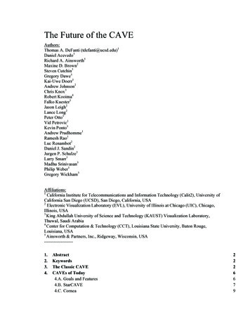
Figure 1. The “classic” CAVE is a multi-person, room-sized, high-resolution, 3D video and audioenvironment. Early CAVEs had less than a megapixel per wall per eye; newer ones have up to 15times as many pixels. Photo: National Center for Supercomputing Applications at University ofIllinois at Urbana-Champaign.Note: All the photographs in this article were shot with the stereo turned off so the images arenot doubled.
4.CAVEs of Today4.A. Goals and FeaturesThe ideal VR viewing device has been visually portrayed in movies, from the iconic first StarWars movie from 1977, and arguably before. Such systems usually include augmented (seethrough) reality as well so that the 3D immersive correct-perspective imagery is seamlesslymerged into the surroundings, when desirable. Of course, all of the visuals in a movie arecomputer-generated special effects, shot or generated from the movie camera’s perspective, andnot the viewer’s (or actor’s) perspective. Movies are projected on a flat screen, so the portrayal ofa movie’s “VR” display is easily faked. [Figure 2], a composite concept, shows the goals of afully surround autostereo VR system that does not yet exist.Figure 2: A composite rendering of the EVL/Calit2 vision of a future collaboration room.Illustration: Jason LeighThe ultimate hardware design goals for a VR system are:--Compact footprint, so it can fit in work or home spacesScalability, so it can be laptop, desktop, corner-sized, room-sized, or stadium-sizedUsability in normal room lighting, so that other work/play can go simultaneouslyLow noise signature, so that people can talk and generated audio can be heardLow thermal signature, to minimize need for ventilation and coolingPotentially holds several users, and/or is network connected, to allow collaborationExtended service intervals and easy access for maintenance, to reduce expensePower-efficient, to reduce cost and coolingArticulated, easily shippable screens and rapid installation/de-installation for field andtraveling exhibit use
-Low cost, so that ubiquity is conceivable.Desirable software and input/output VR features include: High resolution, so virtual images are seen as sharply and in as much detail as in reality High brightness and contrast, so colors are vibrant and not washed out or dim Production of computer graphics and the display of captured imagery, that is equivalentto or exceeds human visual acuity, in 3D with the correct viewer-centric perspectiverendering for every viewer Input and full recognition of the viewer’s or viewers’ being and actions, includingspeech, non-verbal utterances/noise making, and gestures Audio (sonification) at or exceeding human aural acuity, fully surround, listener centeredand focused Touch (tactile) input from the user and touch output from the VR system, allowing hapticinput and feedback, for all users, for example [Harrison10] Olfactory (smell) output delivered to each user, and input recognition as well Taste output and input recognition Linking such devices together with near-zero latency and no noticeable compressionartifacts No user encumbrances (special glasses, headphones, nose tubes) except as desired fortouch feedback and taste.Much as color television replaced black and white television, VR practitioners want to reduce theobjections to VR down to the point that 2D visualization devices are no longer for sale: i.e., likecolor, one buys a display and gets 3D for free, but could turn it off when preferred. To do this,displays need to (at least appear to) be large (that is, the edges are generally outside the viewersfield of view) and the viewer(s) need(s) to be tracked accurately. Such VR capability is becomingavailable, even in the home, although the price is not asymptotically approaching the cost of 2Ddisplays. Audio capability, however, is somewhat more available to consumers, and tactileinput/feedback has long been a feature of consumer gaming controllers of various sorts. Taste andsmell are still challenges, occasionally investigated. Tele-immersion (linking VR devices overnetworks) is routine at latency approaching that dictated by the speed of light in fiber, althoughcompression is still a requirement due to bandwidth speeds.4.B. StarCAVEThe StarCAVE [DeFanti08a] [Figures 3, 4], designed and built at UCSD/Calit2, is a 5-wall plusfloor projected VR room, operating at a combined resolution of 68 million pixels, 34 millionpixels per eye, distributed over 15 rear-projected wall screens and 2 down-projected floor screens.The StarCAVE is a surround system diameter of 3m and height of 3.5m. Its 15 wall screens arenon-depolarizing high-contrast rear-projection screens, stacked three high, with the bottom andtop trapezoidal screens tilted inward by 15 degrees to increase immersion, while reducing stereoghosting. The screens are 1.19m high by 2.13m wide, narrowing to 1.66m at the top and bottom.The pentagonal floor images are projected from overhead onto a non-depolarizing, coated floor.User interaction is provided via a wand and multi-camera, wireless tracking system.
Figure 3. Calit2’s StarCAVE from above. Photo: Tom DeFanti.Figure 4. Calit2’s StarCAVE. Illustration: Greg Dawe.
4.C. CorneaCornea [Figures 5-8] is a Mechdyne-designed and built 6-sided 16-Megapixel/screen CAVE-likeproduct built first at Iowa State University as the C-6. C-6/Cornea’s 4,000x4000 projected pixelresolution per screen (four 4K projectors per screen – two sets of 2x1 layout for stereo) is asignificant improvement over the classic CAVE resolution of 1000x1000 per screen.Figure 5. Cornea with door screen open.Photo: Tom DeFanti.Figure 6. Cornea archeology application withusers. Photo: Tom DeFanti.Design objectives for the Cornea were to:-Create the highest resolution, brightest CAVE possible in 2009Fully enclose the participants in visualsProvide high-fidelity user trackingIncorporate spatialized sound including variable, interactive model-based reverberationAllow tele-immersion via 10Gb/s networkingCapture and transmit sessions with switched and transmissible audio and HD videoCornea is currently, in 2010, the world’s highest resolution and brightest virtual environment.Each of Cornea’s six 3m-by-3m screens is 15-Megapixels/eye (there is some overlap betweentop and bottom projector sets), giving a total resolution of 90-Megapixels/eye, using 24 4K10,000-lumen Sony SXRD [SXRD] projectors (4096 x 2160 pixels each), with 4 SXRDsilluminating each of 6 screens, including the ceiling, floor, and a closable “rear” wall screen. AnNvidia Quadroplex-based cluster drives the projectors using 96 5600-model GPUs.
Figure 7. KAUST’s Cornea. Illustration:Mechdyne Corporation.Figure 8. Cornea upper projectors. Photo:Greg Wickham.Calit2 audio researchers designed the advanced sound system for this a six-sided virtualenvironment, directing Meyer Sound Lab [Meyer] engineers to neither obscure the visualizationscreens with speakers, nor place the speakers too far away, since VR screens can be somewhatacoustically opaque. To contend with these challenges, the Cornea is equipped with 28 speakersand 4 subwoofers outside the screens. The sound system has a sampling rate of up to 96kHz,which is more than two times the sampling quality of a compact disc (44.1kHz). A highersampling rate means the system offers more flexibility in terms of audio playback, and highdefinition performance consistent with state-of-the-art audio production techniques andequipment.Cornea makes it possible for users to record their VR experiences, both visually and aurally. Thefacility can stream 32 channels of high-definition audio and video from Cornea to KAUST’sInteractive Media Room, where it can be recorded and archived. This capability provides aneeded tool for scientists to collaborate with their counterparts at institutes that lack virtualenvironments. Mechdyne engineers designed and implemented this recording capability.The Cornea’s audio system is driven by custom audio switching, routing and rendering softwarethat incorporates the latest advances in realistic virtual acoustic imaging, such as air absorption,Doppler effect, source directivity, reflection/absorption simulation, and convolutionreverberation. This system functions both as an audio rendering engine and as a creative sounddesign authoring tool for Cornea visual applications. KAUST scientists can create audiosoundtracks that correspond to their 3D visual data, so a walk through a virtual architecturalrendering, for example, can include the sound of one’s own voice and footsteps reverberating offthe virtual walls.KAUST has two additional SXRD-based VR facilities for virtual reality research, development,and application use. One is a 75-seat room with a 32-Megapixel/eye stereo VR screen (preciselytwo walls of the Cornea side-by-side, involving eight 4K projectors in a 2x2-paired layout plus aninth projector in the middle). This multi-purpose room also features an advanced audio researchcapability whose description is outside the scope of this paper. The second one is a developmentsystem, the DS-1, which is one-half wall of the Cornea, used primarily by programmers.
4.D. NexCAVEFigure 9. Tom Levy and Sami Maghlooth in the KAUST NexCAVE reviewing the VRreconstruction of UCSD’s excavation at Khirbat en-Nahas in southern Jordan. Content: KyleKnabb and Jurgen Schulze. Photo: Tom DeFanti.Figure 10. KAUST’s NexCAVE showing a stereo 360o scan of the Wisconsin State Capitol (inmono mode). Content: Dick Ainsworth. Photo: Tom DeFanti.KAUST currently has a 21-panel NexCAVE, (which stands for “NewXpolCAVE,” with “Xpol”
being short for “micropolarization”) passive-stereo 3D environment [Figures 9-13].Micropolarization (“Xpol”) is a technique to create stereo images by changing the polarization ofthe video image on a line-by-line basis, alternating between right and left circular polarization[Faris98, Benton99, Arisawa08]. A 1080p HDTV can have affixed to its surface a transparentoverlay of 1080 lines, 540 polarized one direction interlaced with 540 polarized the otherdirection. Besides the relative simplicity of manufacture, it is a passive stereo system that usessimple circularly polarized glasses. Also, it is a spatial technique, so that there is no need tosynchronize left and right eye images, since they are merged (unlike field-sequential stereo,which requires active stereo glasses and, if there are more screens, universal left/rightsynchronization.) For this reason, Xpol displays are scalable using the same techniques as anytiled display.The availability of commercially produced Xpol LCD displays is a recent (2009) advance inmarketing consumer HDTVs. The JVC Xpol 46” display allows 3D generated or scanned stereoimages to be produced in real time as well as played back as HDTV streams. The NexCAVE atKAUST consists of 21-tiled displays (arranged in a 3-high by 7-wide configuration), with the topand bottom tiles tilted inward in order to help preserve polarization (since these displays have alimited vertical angle of view). GPU-hardware accelerated stencil buffer routines are used tocombine left- and right-eye views into a line-by-line alternating image prior to display, at realtime frame rates. This operation is similar to that performed during real-time autostereointerleaving [Kooima07].Calit2’s NexCAVE has 10 panels [Figure 11] (a 3 x 3 array with an additional display at thebottom of the middle column) and was designed for shipping so that it can be deployed inresearch exhibit booths at conferences. Because the NexCAVE operates well in ambient lightingand is free standing, installation/maintenance in a booth or any other work/play space is greatlysimplified. Of course, any complex display like this in a museum or unguarded public settingwould need further enclosure and protection from tampering.
Figure 11. The 10-panel NexCAVE at the SC’09 conference showing content developed by PhilipWeber. Photo: Tom DeFanti.The tilted StarCAVE non-rectangular screen tiling helped inspire the design of the NexCAVE.Polarized screens tend to ghost more (that is, the stereo separation attenuates) when viewed at anangle. The tiles need to be arranged to allow approximately on-axis (that is 90 perpendicular tothe screen) viewing as much as possible. The JVC Xpol display has a broad off-axis horizontalstereoscopic viewing angle of about 140 , but a vertical viewing angle of only 20 . TheStarCAVE’s upper and lower sets of screens are actually cut in the shape of trapezoids and tiltedin, so that the viewer’s line of sight is fairly perpendicular to the screen in typical viewingpositions, and the design of the framing makes the unlit bezel in between screens negligible[DeFanti08a]. Trapezoidal LCD panels are conceivable, but not likely to hit the market anytimesoon, so the NexCAVE’s required tilted-in screens are physically achieved by overlapping JVCXpol screens, including positioning the bezels behind one another, which helps minimize theirperceived thickness [Figures 12, 13]. This arrangement works well and is not disruptive whenviewing 3D scenes if one does not specifically pay attention to the bezels. The NexCAVE’soverlapping panels are not very visual distracting in practice. (A different tiling is proposed forthe NG-CAVE, Section 5F.) When some detail is blocked by a bezel, the tracked viewer justnaturally moves a bit to look around the bezel, just as one would look out a window with
mullions. Also, just as in the case of a window, vertical bezels are perceived less than horizontalbezels for virtual objects which do not happen to be in the screen plane, because due to thehorizontal offset of human eyes, at least one eye can see the object at all times. (Allaccommodation information in any VR system is essentially incorrect, unless the z-position of theviewed object happens to be at the same distance from the viewer as the screen, so having afragmented image wrong in a variety of places instead of one place is not any more incorrect ordisturbing.) Of course, narrower bezels would be better, as in the AESOP display and NG-CAVEdiscussed below in Sections 5.E-F.So far, a NexCAVE with a full floor and ceiling has not been attempted, although with theappropriate structure for the overhead tiles and a strong and clear surface to stand on, a moresurrounding NexCAVE could be built. The space between the overlapping NexCAVE screensprovides an opportunity for forced air ventilation, eliminating one design/usage problem withfully surround CAVEs mentioned above.Figure 12. The back side ofthe KAUST NexCAVE.Photo: Tom DeFanti.Figure 13. The KAUST NexCAVE turned off to show thestructure designed and built by Greg Dawe. Photo: Tom DeFanti.The NexCAVE advances VR in three important ways over projector-based systems. First, asnoted above, dozens of projectors are really hard to accurately align and keep aligned due to thedimensional instability of the projectors, cradles, and screen systems. The result is that the user’seye/brain system needs to do the “final” alignment. Since the NexCAVE panels’ left- and righteye images are perfectly aligned, the eye/brain fatigue caused by imperfect alignment in projectedclassic CAVEs and the StarCAVE seems to be greatly mitigated according to users. Ideally, anexperiment by independent researchers needs to be run to verify this opinion.Second, the contrast offered by the NexCAVE has been measured by the first author to be inexcess of 300:1, or 10 times that of the StarCAVE (30:1) and 100 times that of the Cornea (3:1)[Figures 14-16]. The whites should be as white as a white shirt, and the blacks as black as a blackpair of pants. The lack of contrast in classic CAVE screens motivated the development of newscreens for the StarCAVE [DeFanti08a], but it would be difficult to make StarCAVE screenslarge enough and to suspend them overhead to create the classic CAVE’s 3m-by-3m walls.Third, the articulation and modularity of the screens in the NexCAVE are a contribution to thefuture of the CAVE, in that shipping, installation, expansion, and de-installation are rather
straightforward compared to classic CAVEs.Figure 14. KAUST Cornea checkerboard pattern.Photo: Dan Sandin.Figure 15. Calit2 StarCAVE checkerboard patternPhoto: Jurgen Schulze.
Figure 16. KAUST NexCAVE checkerboard pattern. Photo: Daniel Acevedo.4.E. Design Challenges with Today!s CAVEs4.E.1. Projector-based CAVE Design ChallengesProjection-based CAVEs have many design constraints that prevent designers from approachingthe goals specified in Section 4.A, and thus limit CAVE ubiquity, namely: 10m3 or larger spaces are not commonly found or easy to justify; buildings normally needto be built around such spaces at great expense. CAVEs are architectural achievements aswell as technical installations. Power and air conditioning needs of projected CAVEs are high (e.g., 25-100 kW). CAVE projectors are expensive, heavy, and, as with all projectors, require re-lampingevery 800-2000 hours of use. Lamps range from several hundred to several thousanddollars each; classic CAVEs have 4-24 projectors with one or two lamps each. CAVE screens face each other and thus, unlike single screens in movie theaters, pick uplight from each other and are further illuminated by any ambient lighting, which meansthey are best viewed when the ambient lighting is very low and the screens themselvesare made of dark-surface projection material. Projectors also have hot spots and off-axisintensity attenuation issues, which can be compensated for with extra rendering, giventhat the location of the tracked viewer is known [Rhee10]. Hard-surface rear projection screen systems have odd sounding acoustical signatures dueto uncontrolled reflections, standing waves and room modes. They also inhibit the abilityto project sound directly to the listener, meaning that speaker-produced sound will tend toreinforce the room’s odd acoustical quality. Softer surface rear projection screens are
better sounding; they can pass some sound directly to the listener. In both cases,significant analysis and equipment investment is required to address the screen-basedacoustical anomalies. Alignment of the projectors is difficult and time consuming, more so as the number ofprojectors increases and one wraps around in all dimensions. Cheaper projectors typicallyhave no auto-alignment features to help this, and are built into cases that warp a bit asthey warm up, further frustrating the goal of pixel-perfect alignment. Expensiveprojectors with sophisticated mounting and auto alignment systems are better, but thedifferential expense per projector (perhaps 5-10x) has to be multiplied by the number ofprojectors to appreciate the additional cost. Software can mitigate the problems ifperformance penalties incurred by the extra rendering/compositing needed is acceptable.This is an area of continuing research.A primary goal for the CAVE of the future is to allow CAVE-like surround VR in a normal workor home environment, that is, in a 3m-by-3m-by-3m or even smaller room (most office/labspaces have nearly 4m between the floors, although 1m of that is often taken by ducts, pipes, andconduit). In order to do that, projection needs to be eliminated, and the CAVE of the future has tobe constructed from self-illuminating panels of some sort.A further goal of the CAVE of the future is to offer contrast (and saturation) as good as modernhome HDTV displays, that is, greater than 1000:1. Internal light spillage and reflections attenuatecontrast in projector-based CAVEs due to the screen material typically used. Bright surroundscenes offer grays at best, not blacks, and rather unsaturated (pastel) colors. Consumer paneldisplays, it should be noted, have coatings that are effective in reducing the effects of spillage andreflection.4.E.2. Panel-based CAVE Design ChallengesPanel-based CAVEs have the following design challenges: A 3m-by-3m-by-3m display would need to be built using many panels, given current(2010) display size and resolution. Consumer 3D-capable panels, however, are modestlypriced ( 2,000- 5,000 depending on size), so cost isn’t the critical issue (compared to theexpense of classic CAVEs). Panel power consumption is 150W to 250W each,substantial, but lower than classic CAVE projectors which can be 1000s of watts. 3D-capable consumer panels are designed to be viewed conventionally, that is, notseverely off-ax
environment. Early CAVEs had less than a megapixel per wall per eye; newer ones have up to 15 times as many pixels. Photo: National Center for Supercomputing Applications at University of Illinois at Urbana-Champaign. Note: All the photographs in this article were shot with the stereo turned off so the images are not doubled.