Transcription
FGCSFuture Generation Computer Systems 00 (2017) 1–10A Programmable Policy Engine to Facilitate Time-efficient Science DMZManagementChen Xu1 , Peilong Li1 , Yan Luo1University of Massachusetts Lowell, One University Ave, Lowell, MA, USA, 01854AbstractThe Science DMZ model employs dedicated network infrastructures and advanced software techniques for large-volume scientific researchtraffic flows targeting high-throughput and low-latency data transfer. However, current Science DMZ framework lacks of efficient means of userintent expression and suffers from slow service-delivery due to the manual work involved in the management loop. As a result, a programmableinterface that facilitates user-administrator communication in a time-efficient manner is highly demanded. In this paper, we introduce FLowell,an enhanced SDN-powered Science DMZ model deployed on our campus network. Moreover, we propose a programmable policy engine atopthe SDN controller that allows network administrators to implement configuration policies in order to manage the network, while simultaneouslyoffering rapid response time network resource request policies for end users. Our experiment results show that user intent in FLowell can beresponded and serviced within 1 second. In addition, FLowell reduces the network latency for the research network path by 35%, and boost thedisk-to-disk throughput by up to the 10 Gbps line rate.Keywords: Science DMZ, Software Defined Networking, Policy Engine, Fast Service Delivery1. Introductionconstitutes a Change Advisory Board (CAB). Network administrators from CAB are mandated to meet every Thursday toESnet has proposed the Science DMZ model [1], a scalapprove or deny changes. All requests to CAB must be subable model designed for local campus networks, to satisfy themitted by Monday for review on Thursday in the same week.increasing demand for high performance scientific research, inMost changes need to be reviewed off hours. Similar situationcluding large data transfers and real-time human to applicationexists in Massachusetts Green High Performance Computinginteraction. With Software Defined Networking (SDN) techCenter (MGHPCC) [5] as the administrators work on the reniques emerging as a preferred solution for network managequests every Tuesday. In order to accelerate this inefficient inment, decoupling the control plane from the data plane withinteraction, the entire process must be automated, which in turnthe context of a Science DMZ network environment enables efrequires the consideration of four key requirements. Firstly,ficient rule-based network control and significantly reduces thein order to replace more traditional methods, such as phonerequired time for network configuration as well as troubleshootcalls or emails, users will require a more effective method toing [2, 3, 4].submit their requests. Secondly, users should have the abilityAlthough network administrators need not log into networkto submit high level requests that do not depend on intricatedevices in order to manually apply network configuration changes, knowledge of the low level details regarding the design of thewhen leveraging SDN-based techniques, there exists a pronounced network. Specifically, users should only have to specify thelatency between the time a user sends a request for a networksource and destination for the corresponding network resourceresource and the time the request is serviced by the network.request. As a result, user requests will have to be convertedIn this case, inefficiencies continue to endure in the interactioninto detailed network configuration settings for the appropribetween users and network administrators, which indicates anate switches. Thirdly, understanding there should be a rapidongoing need for manual intervention. For example, the Uniresponse time, a given user’s request should be serviced in aversity of Massachusetts Lowell (UML) campus IT departmentmanner that reduces the required processing time as well as theamount of manual labor carried out by a network administrator.Email addresses: Chen Xu@student.uml.edu (Chen Xu),Lastly, although such a process will automate some portion ofPeilong Li@uml.edu (Peilong Li), Yan Luo@uml.edu (Yan Luo)1
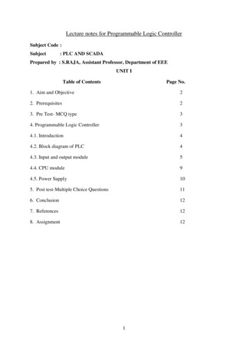
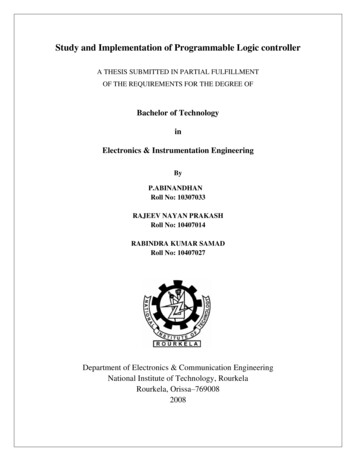
C.Xu et al. / Future Generation Computer Systems 00 (2017) 1–10a network administrator’s work, the process itself still needs tobe under the control and management of the administrator.In this paper, we introduce FLowell, an enhanced networkinfrastructure consisting of a SDN-based Science DMZ thatsupports various forms of data-driven scientific research conducted at UML. Furthermore, FLowell is designed to accelerate large data transfers from UML to MGHPCC, which willbe demarcated from the general purpose, campus productionnetwork. Moreover, we propose a programmable policy engine on top of the control plane to allow science research teamsfrom different departments the ability to access Science DMZresources under the purview of FLowell. In this case, the overarching goal is to reduce the requirements in terms of the timeto service a resource request as well as the level of manual intervention on the part of a network administrator.In this paper we make the following contributions. 1) Wedesign a set of simple and human-readable policy rules for defining the network data paths between end hosts and network resources. 2) We design a policy engine that provides users withpolicy rules for rapid response time network resource requests,independent of whether the requests can be serviced. 3) Wedesign a policy engine that allows administrators the ability tomanage data paths irrespective of whether they were generatedfrom a user request or from a newly defined network administrator policy. 4) We design a policy engine that converts policyrules to OpenFlow rules so that the low level knowledge of theunderlying network infrastructure is transparent to end users.The remainder of the paper is organized as follows. In Section 2, we introduce the ESnet Science DMZ model along withour FLowell Science DMZ deployment. In Section 3 we provide the underlying motivations for our work. Subsequently,we describe the policy engine in Section 4. Afterwards, weevaluate the performance of our work within Section 5. Furthermore, in Section 6 we provide a survey of work related toFLowell. Finally, we provide our conclusions in Section 7.2to facilitate the flexible provisioning and routing of networkflows. This reference model relies upon OpenFlow switchesto manage and differentiate the various network flows, whilesimultaneously enforcing network security policies.Figure 1: ESnet Science DMZ Reference ArchitectureInternetControllersHostMgmt SwitchperfSONARHostHostMgmt SwitchMgmt SwitchAggr SwitchOF SwitchBMFInternet2Mgmt SwitchDTNHostHostMgmt SwitchScience DMZBroESnetInternetFirewallMgmt SwitchCampus LANMGHPCCperfSONARFigure 2: FLowell Science DMZ Network2. Background2.1. ESnet Science DMZ ModelNetworks in research institutions and organizations normallyservice two types of traffic, specifically operational businessrelated traffic and scientific research related traffic. However,the majority of the existing campus networks are optimized forbusiness operations, which are incapable of providing low latency, real-time transfers for large scale data. The lack of support for such large scale data transfers within the context of today’s network infrastructure serves as a prominent obstacle thathinders the realization of numerous scientific research objectives. As a result, ESnet proposed a Science DMZ model [1] inorder to overcome the aforementioned challenges. The ScienceDMZ model accomplishes this by separating the specificallyengineered high-performance data-intensive science network,i.e. the Science DMZ, from the general-purpose network. Asa result, each portion of the network can be optimized withoutinterfering with the other.Figure 1 [6] presents the Software-Defined Networking (SDN)based Science DMZ reference architecture proposed by ESnet22.2. FLowell Science DMZFLowell refers to ESnet Science DMZ model and leveragesexisting campus cyberinfrastructure resources such as the campus data center, computing clusters located at research laboratories, along with a programmable network test bed consistingof network processors to realize our Science DMZ on campus.As illustrated in Figure 2, the 10 Gbps network connection fromUML to MGHPCC serves to bridge on campus researchers witha massive pool of shared computing resources, while the 10Gbps Layer 2 connection provides a gateway to national research and education networks including Internet2 and ESnet.2.2.1. UML Campus NetworkThe campus network is designed to meet the following objectives. 1) A host that is assigned a private IP address, but nota public IP address, should be allowed to access both public andprivate networks. 2) The network should be able to dynamicallyfilter out and redirect large data flows from the full set of traffic.
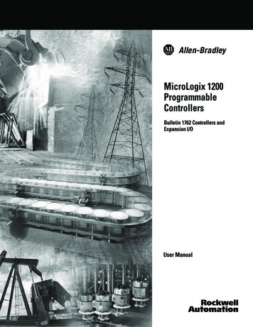
C.Xu et al. / Future Generation Computer Systems 00 (2017) 1–103) The network should provide a full 10 Gbps optic-fiber pathfor all data transfers. Cognizant of the previously stated goals,we deploy the following elements into our campus network.Management Switch – Management switches are currentlyinstalled in on campus buildings, and directly face the end hostsin the research laboratories. In addition, the management switchesserve to transfer research data from UML to MGHPCC, wherethe information is stored within a Date Transfer Node (DTN).Furthermore, the management switches provide the opportunity for further scalability in the event that the number of hostsshould increase in the future. The high availability (HA) enabled management switches also ensures zero downtime of thenetwork operation.Aggregate Switch – An aggregate switch is included in ourdesign in order to 1) build the connectivity between buildings toallow the data transfers in campus Local Area Network (LAN)without need for SDN control; 2) accumulate traffic from oncampus buildings and send the resulting traffic to the OpenFlow switch through a single output port. The aggregate switchserves to overcome the lack of support for the FLOOD actionby the OpenFlow switch. Given that all traffic emanates froma single port, rather than multiple ports, the aggregate switchserves to minimize the number of wildcard rules and conflictsin a coarse-grained manner, particularly with reference to thenumber of rules for handling ARP packets.OpenFlow Switch – An OpenFlow switch forwards packets to different destinations based upon the appropriate flowrules. We define the flows into two types, namely an ElephantFlow if it is large continuous data flow and the destination isMGHPCC, and a Mice Flow if the flow needs to go to the Internet.Big Monitoring Fabric – We deploy a Big Monitoring Fabric (BMF) network packet broker to operate within inline mode[7] with service chains designed to enable network admins toeasily deploy and manage inline security or analytics tools so asto ensure the resilience against network or tool failures. We create two chains, namely (an Elephant Chain and a Mice Chain)for the two types of flows mentioned above. For the Mice Chainwe apply a series of services including a Bro, a firewall, as wellas a NAT (introduced in the next paragraph).Software – The following software solutions are leveragedfor the purposes of network control, network monitoring, network security and network measurement. The OpenDayLight(ODL) controller [8] and the Big Mon Controller [7] managethe control plane for the OpenFlow switch and the BMF respectively. The Bro [9] IDS is a powerful network analysisframework. In collaboration with the ODL controller, the network security monitor can perform packet analysis, determinethe flow type of the packet, and forward the packet to the appropriate destination by calling the correct ODL API in order toinstall the corresponding rule in the OpenFlow switch. Furthermore, pfSense [10] serves as an open source firewall which cansecure the private network while providing NAT services forprivate IP addresses. Moreover, perfSONAR [11], widely usedin the context of science networks, provides our design with thenecessary network performance measurement infrastructure.On the start of the system, the ODL controller connects to33the appropriate OpenFlow switches. Then, the Bro IDS beginsto monitor the network activities of the Mice Chain, while managing the wildcard rules for ARP packet handling and ensuringthat packets forwarded to the Mice Chain are installed in theappropriate OpenFlow switch.As shown in Figure 3, once a host starts sending packets:1 The Mgmt. & Aggr. switches forward the traffic to OpenO2 As a result of the pre-installed rules the trafficFlow switch. O3 The BMF fabric spanswill be forwarded to the Mice Chain. Othe traffic to the Bro IDS, which captures the packet’s sourceIP along with the destination IP and decides if the flow is an4 If the desElephant Flow based on a white list table lookup. Otination IP address corresponds to a Mice Flow destined for theInternet, the Bro IDS will perform no action and the traffic willpass through firewall. The firewall will NAT the private source5 The traffic is sent to theIP address to a public IP address. O6 If the destination IP address is part of thepublic network. OMGHPCC network, the Bro IDS will call the appropriate ODL7 The ODL controller will install the corresponding flowAPI. O8 Subsequent packets will berules into the OpenFlow switch. O9 Packets part of the Elephantre-routed to the Elephant Chain. OChain will be forwarded to MGHPCC.Figure 3: FLowell Network Flow2.2.2. MGHPCC NetworkThe MGHPCC network serves two functions, namely 1)hosting a Data Transfer Node (DTN) in order to store large scientific, research data and 2) sharing the research data with othersites including, for example, AL2S [12] and Internet2 [13]. InMGHPCC, we deploy a Dell PowerEdge R730 server with storage directly attached to it as our DTN. The DTN has a private10Gbps connection for data transfers to or from campus anda public 10Gbps connection for sharing data with the Internetand other sites. Two different data transfer tools are served onthese networks. Globus serves to manage data transfers over thepublic network, whereby a Globus Connect Server (GCS)[14]configures the DTN as a Globus endpoint. Globus enables allusers with local accounts on the DTN to share and transfer filesto or from this endpoint. Users need to install the Globus Connect Personal (GCP)[15] client onto their computer in order toconnect to the GCS server. Fast Data Transfer (FDT)[16] servesto manage data transfers over the private network. FDT has thecapability to perform efficient data transfers at disk speed overnetworks with standard TCP. Globus and FDT were selected fortheir ease of use and for their support of all major platforms.
C.Xu et al. / Future Generation Computer Systems 00 (2017) 1–104Table 1: Software Deployed in FLowell Science DMZSoftwareOpenDayLight ControllerBig Mon ControllerBropfSensepfSONARFunctionNetwork ControlNetwork ControlNetwork Monitor & AnalysisNetwork SecurityNetwork MeasurementDescriptionThe control plane for OpenFlow switchThe control plane for BMFMonitor the network traffic and filter Elephant Flow from itProtect the LAN from external attack and do NATing for private IP addressProvide some active network measurement tools3. Motivationpath from host1 in RIP1 to destination dst1 in RIP2 , while another user requests a path from host2 in RIP1 to dst2 in RIP2 ,both are legitimate requests. However if dst1 and dst2 are ontwo different physical ports of the OpenFlow switch, there areno rules to direct the two user requests to the correct outputport.Secondly, an OpenFlow switch is constrained by memoryresource limitations that should not be squandered. If the preinstalled static rules are too fine-grained to direct every flowof the network, we may unnecessarily consume considerablememory resources on the switch. Furthermore, copious entrieswithin the switch will increase the flow table lookup time dramatically and adversely effect performance within the latencysensitive Science DMZ network.Therefore, a white list is necessary in our solution and theflow rules will be installed in the switch after users submit theirrequests. What’s more, we design a module in our policy engine to check flow conflict dynamically before a flow rule isinstalled. Thus, only necessary rules can be pushed to OpenFlow switch so as to save the memory space and the rules arefine-grained without conflict.Our goal is to build a policy engine, a human-friendly andautomated system to dynamically dealing with users’ specifiednetwork resource request policies. To make this realized, weneed to solve the following questions.3.1. Question 1: How Can We Speedup the Service DeliveryProcess for an End User’s Request?Firewalls installed on campus and enterprise networks helpprevent malicious external network traffic from entering LANs.In the context of an SDN-powered Science DMZ, an OpenFlowswitch functions as a Layer 2 firewall as packets need to matchrules installed within the switch in order to pass through theswitch. The pre-installed firewall and OpenFlow rules can onlycover the most basic of network activities, such as website navigation as well as sending or receiving emails. However, if anetwork user wants to access a particular external resource thatis restricted by the current rule set, then the user must requestaccess from a network administrator. The user-admin interaction process is normally carried out by way of email or phonecalls, which is not only extremely inefficient, with resolutiontypically occurring within the span of hours or days, it lacksstrong accountability.To remove the human interaction element from the processand speedup the service delivery time, we propose a policy engine design that enables network users and network administrators to work in a time-efficient manner. In particular, endusers can submit their network resource access requests via aweb graphic interface built on top of our proposed network policy rules. The user can receive an immediate response to theirrequest, either accepted or rejected, depending on whether therequest complies with a predefined set of criteria, i.e. a whitelist, setup by the network administrator.3.3. Question 3: How Can We Map an End User’s Request toa Set of Network Rules?In a Science DMZ, an end user typically has no prior knowledge regarding network operation and network hardware configurations. Therefore, from an end user’s perspective, it is idealto simply submit a network resource request and have the system determine the necessary optimal path. For example, an enduser first provides the source, host name, and destination, service name, corresponding to the task at hand. Subsequently, thesystem verifies the legitimacy of the request. If the request isvalid the system will find a load-balanced path between the requested source and destination, and provide the number of inputand output ports along the path.To this end, we provide a set of policy rules to help expressthe user’s intention, and design a policy manager inside a policyengine in order to parse the intentions from users as well as togenerate the final set of OpenFlow rules. The policy managerinteracts with the SDN controller in order to maintain the existing rule set as well as to install any missing rules. Given thecapabilities afforded to us by SDN, the centralized controllermaintains a global view of the entire network topology. Hence,we can readily find an optimal path in order to satisfy a givenuser’s request.3.2. Question 2: Why Not Use Static OpenFlow Rules?The first question leads us to the next, namely why a whitelist is employed to respond to a given user’s request rather thansimply placing static rules into an OpenFlow switch. We answer this newly proposed question from two different aspectsdepending on the granularity of the rule.Firstly, if entries in a white list are expressed in a coarsegrained manner in order to match the majority of the user requests, then routing conflicts may occur. As an example, suppose an entry from the white list permits all packets from IPrange RIP to pass through the switch. When a user requests a4
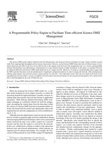
C.Xu et al. / Future Generation Computer Systems 00 (2017) 1–104. Designstoring the rules to the policy repository. As shown in Table3, in order to service the various tasks, the policy manager canbe divided into four components, namely the policy parser, thepolicy checker, the policy converter and the policy implementer.We explain the functionality of each block in details as follows,and the pseudo-code demonstration is shown in Algorithm 1.When the policy manager receives a policy rule from theGUI, it first calls the policy parser function to parse the policyusing regular expressions (RegEx), extracts the values of thekeywords referenced in Table 2 and check if all values are valid,for example an IP address should be described with the correctformat and range. If the policy originates from a user, the policy manager performs a white list look up to verify whether therequest is permitted. Afterwards the policy manager verifieswhether or not the requested network path is duplicated in theFlow array by calling the policy checker function. In this case,we must perform duplicate detection as repeated requests mayresult in flow rule conflicts within the OpenFlow switch. If thepolicy originates from a network administrator, the installationoperation will skip performing the white list lookup, but willcontinue to check for duplicates. Furthermore, we validate theexistence of a path in the event an administrator would like toremove a path due to some reasons, e.g., malicious activitiesdetected on this path. Subsequently, the policy manager callsthe policy converter function to extract the network topologyfrom the ODL controller, constructs a graph of the topology,determines the shortest network path by employing Dijkstra’salgorithm and generates a flow object that contains the rules tobe installed within the network. The example below illustratesthe format of a flow object. For this object, the path key contains the user’s requested path, while the connector key lists theswitches as well as the ingresses and egresses along the networkpath. Subsequently, the policy implementer method is calledto update the Flow array or the Pending array depending on theresults of the policy checker function. Figure 5 illustrates thework flow carried out by the policy manager.As shown in Figure 4, our FLowell Science DMZ infrastructure leverages a policy engine on top of the control plane,which is capable of receiving and imposing policy rules. Byleveraging the policy rules and the corresponding policy engine,users can easily request network resources and network administrators can simplify network path configurations by avoidingsome forms of manual work. The policy engine consists of aweb based GUI, a policy manager and a policy repository. Wewill discuss the details for each portion of the design in the following subsections.Web GUIDTNPolicy licyCheckerPolicyImplementerComputingPolicy EngineHost 1Host 2ODLBroOpenFlowSwitchBMFMgmtSwitchperfSONARScience DMZFigure 4: Components of the Policy Engine4.1. Policy RuleGiven that users and administrators may not necessarily havein depth programming knowledge, we design a simple and intuitive policy rule set. The policy rule consists of three keywords,1) the source IP address, specifying the end host, 2) the destination IP address, representing the network resource, and 3)the flow operation to perform, in terms of whether to establisha new data path or remove an existing one. The resulting keyword combination specifies a request suitable for configuring aparticular network path. Table 2 provides details regarding eachof the policy rule fields. For the sample policy provided below,a user intends to request that a path be established from 10.0.0.1to 10.0.0.2.flow obj {0 path0 : [0 10.0.0.10 ,0 10.0.0.20 ],0connector0 : [[0 switch10 ,0 10 ,0 20 ], [], [].]}Src IP : 10.0.0.1,Dst IP : 10.0.0.2,Flow OP : install4.3. Web-based GUIWe provide a simple and intuitive web based GUI to allow authorized network administrators and end users the abilityto easily create and implement policy rules. Within the GUI,we provide a set of forms so that users can fill in the sourceand destination IP addresses along with the operation to be performed. Users can conveniently issue their policy request via asubmit button. Furthermore, end users can verify the result ofthe submitted network resource request through the same GUIinterface, while network administrators can view all approvednetwork paths and pending paths in order to better understand,control and manage the network.Table 2: Policy Rule KeywordsKeywordSrc IPDst IPFlow OP5ValueIP address of the end hostIP address of network resourceinstall, remove4.2. Policy ManagerIn the policy engine, we implement a policy manager as thecore component responsible for receiving policies sent by usersand network administrators from the web based GUI, parsingthe policies, checking for conflicts, determining the shortest forwarding paths, generating the necessary OpenFlow rules and4.4. Policy RepositoryWe implement a policy repository to store the white list aswell as the flow objects in the Flow array along with the Pending array. The Flow array consists of the permitted paths as5
C.Xu et al. / Future Generation Computer Systems 00 (2017) 1–106Table 3: Functions in Policy ManagerNo.1234Functionpolicy parser(str policy)policy checker (str src ip, str dst ip, str flow op)policy converter (str src ip, str dst ip)policy implementer(dict flow obj,str flow op)ExplanationParse the policy and check for validationCheck for feasibility and rule existenceMap policy to flow rule(s)Install flow rule(s) into the systemAlgorithm 1 Policy 33:34:35:36:37:38:39:Parse policyIn WL?NoIn PendingArray?YesIn FlowArray?NoAdd path toPending ArrayYesYesDo nothingViewed byadminNoQuery networkTopologyCalculate theshortest pathConvert to FlowObjectAdd Flow Objectto Flow ArrayFigure 5: Policy Manager Work Flowwell as flow installation information, while Pending array givesthe paths that are not listed in the white list a second chanceand these paths will be viewed by administrators for further decision. Thus, we increase the error-tolerant rate in case of therequest path is reasonable but not in the white list. There arethree reasons why the arrays needed to be stored. 1) Upon receipt of a packet the Bro IDS will need to inspect the Flowarray in order to determine if the packet matches one of the approved paths and if so fetch the corresponding flow installationinformation. 2) A user will need to check the GUI interface inorder to determine if the requested flow has been approved. 3)Administrators will need to inspect the GUI interface in orderto collect a comprehensive list of the approved network paths.Policies will be stored in the repository in the following format.WL[] : array for white listFlow[] : array for approved pathPending[]: array for pending pathdict f low ob j: flow objectfunction policy parser(policy)Use regex to extract values from policy according to keywordsif all values are valid thenreturn src ip, dst ip, f low opfunction policy checker(src ip, dst ip, f low op)f low [src ip,dst ip]if U ser and f low in WL or Admin thenif f low op is ”install” and f low not in Flow thenf low ob j policy convertor(src ip, dst ip)policy implementer( f low ob j, f low op)else if f low op is ”remove” and f low in Flow thenf low ob j[’path’] f lowpolicy implementer( f low ob j, f low op)else if U ser and f low not in WL thenf low ob j[’path’] f lowpolicy implementer( f low ob j, f low op)return f lagfunction policy converter(src ip, dst ip)Call ODL API to get the detail of network topologyCalculate the shortest path for given src ip and dst ipDetermine the in and out ports of each switch in the pathGenerate f low ob jreturn f low ob jfunction policy implementer( f low ob j, f low op)if 0 connector0 in f low ob j and f low op is ”install” thenAdd f low ob j to Flowelse if flow op is ”remove” thenRemove f low ob j from FlowRemove corresponding flow(s) from OF switchelseAdd f low ob j to PendingThe policy engine control flow, shown in Figure 6, can bedivided into the control path for a user and the control pathfor a network administrator. The difference between the twocontrol flows is that network administrators have the necessaryprivileges to remove an approved path from the network, whileend users can only request that a flow be instantiated.End User’s Control Path: An end user, e.g., a researcher,will first create a policy through the web based GUI and sendit to the policy manager. The policy manager then parses thepolicy to determine the next course of action. Upon receiptof a new packet, the Bro IDS verifies whether the source anddestination IP address pair is in the Flow array within the policyrepository. If so, the Bro IDS will fetch the network connectionFlow [{0 path0 : [0 10.0.0.10 ,0 10.0.0.20 ],0connector0 : [[0 switch10 ,0 10 ,0 20 ], [], [].]}, {}, {}.]4.5. Policy Engine Control FlowIn this subsection, we discuss how the components of thepolicy engine collaborate with one other in order to carry outautomated network resource control as well as management.6
C.Xu et al. / Future Generation Computer Systems 00 (2017) 1–10UserUsersend policy viaweb GUIPolicyManagerPolicy Engine7tions of the machines we used in the two experiments are listedin Table 4.NetworkAdministratorInternetif remove pathparse, check,convert & savePolicyRepositorypublicpublicDTNprivateScience DMZprivateDTNretrive flow
DMZ model accomplishes this by separating the specifically engineered high-performance data-intensive science network, i.e. the Science DMZ, from the general-purpose network. As a result, each portion of the network can be optimized without interfering with the other. Figure 1 [6] presents the Software-Defined Networking (SDN)