Transcription
General Electric Systems Technology ManualChapter 2.5Main Steam System
TABLE OF CONTENTS2.5 MAIN STEAM SYSTEM . 12.5.1 System Purposes . 22.5.2 System Flowpaths . 22.5.3 Component Description . 32.5.3.1 Main Steam Lines . 32.5.3.2 Reactor Head Vent . 32.5.3.3 Safety/Relief Valves . 32.5.3.4 Flow Restrictors . 42.5.3.5 MSIVs . 42.5.3.6 Steam Line Drains . 62.5.3.7 Turbine Bypass Valves . 62.5.3.8 Turbine Stop Valves . 72.5.3.9 Turbine Control Valves . 72.5.3.10 Turbine . 72.5.3.11 Moisture Separators/Reheaters . 82.5.3.12 Combined Intermediate Valves . 92.5.3.13 Steam Seal System . 92.5.4 System Features and Interfaces . 102.5.4.1 Normal Operation . 102.5.4.2 Safety/Relief Valve Operation . 102.5.4.3 System Interfaces . 112.5.5 Summary . 13Rev 09/112.5-iUSNRC HRTD
LIST OF -92.5-102.5-112.5-122.5-132.5-142.5-15Rev 09/11Main Steam SystemMain Steam System (Cont.)Auxiliary Steam HeadersMain Steam Line DrainsTwo Stage Target Rock Safety/Relief Valve (Closed)Two Stage Target Rock Safety/Relief Valve (Open)Main Steam Isolation ValveMain Steam Isolation Valve (Open)Main Steam Isolation Valve (Closed)Safety/Relief Valve ArrangementMoisture Separator ReheaterSteam Seal Supply SystemMain Turbine Sealing SteamTurbine Gland SealsFeed Pump Turbine Seal Steam2.5-iiUSNRC HRTD
2.5MAIN STEAM SYSTEMLearning Objectives:1. Recognize the purposes of the Main Steam System.2. Recognize the purpose, function and operation of the following major components:a. Safety/Relief /Auto Depressurization Valves in each mode of operationb. Reactor Head Vent Valvesc. Main Steam Line Flow Restrictorsd. Main Steam Line Isolation Valvese. Turbine Bypass Valvesf. Turbine Stop Valvesg. Turbine Control Valvesh. Main Turbinei. Combined Intermediate Valvesj. Extraction Steam Systemk. Moisture Separator Reheatersl. Steam Seal System3. Recognize the following flowpaths for the Main Steam system:a. Safety/Relief /Auto Depressurization Valvesb. Main Steam Line Flow Restrictorsc. Main Steam Line Isolation Valvesd. Turbine Bypass Valvese. Main Turbinef. Moisture Separator Reheaters4. Recognize the plant parameters which will cause the following:a. MSIV Closureb. SRV liftc. RPS bypass of main turbine scrams5. Recognize how the Main Steam system interfaces with the following systems:a. Reactor Vessel System (Section 2.1)b. Recirculation Flow Control System (Section 7.2)c. Reactor Protection System (Section 7.3)d. Condensate and Feedwater System (Section 2.6)e. Reactor Core Isolation Cooling System (Section 2.7)f. High Pressure Coolant Injection System (Section 10.1)g. Electro-Hydraulic Control System (Section 3.2)h. Offgas System (Section 8.1)Rev 09/112.5-1USNRC HRTD
i. Automatic Depressurization System (Section 10.2)j. Feedwater Control System (Section 3.3)k. Nuclear Steam Supply Shutoff System (Section 4.4)2.5.1 System PurposesThe purposes of the Main Steam System are To direct steam from the reactor vessel to the main turbine and other steam loads. To provide over pressure protection for the reactor vessel and reactor coolantsystem. To direct steam to safety systems.The functional classification of the Main Steam System is that of a power generationsystem. Three components, however, are Engineered Safety Features, the Main SteamIsolation Valves (MSIVs), the Main Steam Line Flow Restrictors, and the Safety/ReliefValves (SRVs).2.5.2 System FlowpathsThe Main Steam (MS) System, shown in Figures 2.5-1, 2.5-2, 2.5.3, and 2.5-4, consistsof four steam lines that originate at the reactor vessel. Within the drywell each steamline contains a number of SRVs that provide a flow path to the suppression pool forreactor coolant system over pressure protection, a steam flow restrictor to limit the lossof inventory in the event of a steam line rupture, and an inboard main steam isolationvalve. The "A" steam line contains three additional penetrations to provide continuousventing of the reactor vessel head during reactor operation, a steam source to theReactor Core Isolation Cooling (RCIC) System, and the High Pressure Coolant Injection(HPCI) System.The 4 main steam lines penetrate the drywell, traverse the reactor building in a shieldedsteam tunnel and in the turbine building combine at the pressure equalizing header.From the pressure equalizing header, steam is directed to the Main Turbine, BypassValves (BPVs), Reactor Feed Pump Turbines (RFPTs), Steam Jet Air Ejectors (SJAEs),Radwaste Steam Generator, and the Steam Seal Evaporator.Steam line drains are provided throughout the system to remove moisture from lowpoints in the steam lines and to provide a method of equalizing pressure around theMSIVs. The steam line drain header leaves the Drywell via a motor operated isolationvalve and a guard pipe, an outboard isolation valve and from there drains to the maincondenser.Rev 09/112.5-2USNRC HRTD
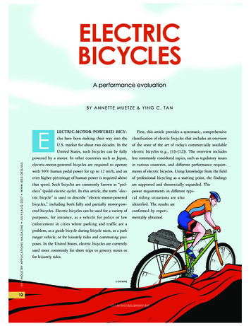
2.5.3 Component Description2.5.3.1 Main Steam LinesThe main steam lines, shown in Figures 2.5-1, 2.5-2 and 2.5-4, are twenty-four inchdiameter carbon steel pipes. The lines are welded to the reactor vessel shell area andhave a design pressure and temperature of 1250 psig and 575ºF, respectively. Thesystem design and arrangement incorporates seismic considerations and provisions tomitigate the consequences of postulated pipe failures.The use of four steam lines, to control a flow of 10.5 x 10⁶ lbm/hr of reactor steam,provides a limitation on the differential pressure across reactor vessel internals during asingle steam line break. The steam dryer differential pressure is of particular concernbecause failure of the dryer could result in interference with MSIV closure and thusprevent isolation.2.5.3.2 Reactor Head VentAs shown in Figure 2.5-1, a vent connection is provided on the top head of the reactorvessel. This serves to vent noncondensible gases from the upper vessel area duringstartup and normal operation. During operation at temperatures less than boiling, thenoncondensible gases are vented to the drywell equipment drain sump. Attemperatures above boiling, the vent is directed to the "A" main steam line.2.5.3.3 Safety/Relief ValvesThe SRVs, Figures 2.5-5 and 2.5-6, prevent over pressurization of the nuclear processbarrier from any abnormal operational transient. In addition to providing over pressureprotection, seven (7) of the SRVs are also used by the Automatic DepressurizationSystem (ADS, Section 10.2) to rapidly decrease reactor pressure during specific loss ofcoolant accidents. There are a total of eleven (11) SRVs, each with an approximatecapacity of 815,000 lbm/hr at 1100 psig. These valves lift sequentially with four valveslifting at 1115 psig, four valves at 1125 psig and three valves at 1135 psig to providevessel overpressure protectionThe SRVs are located on each main steam line between the reactor vessel and thesteam line flow restrictors. The SRVs have three modes of operation; The safety mode, the valve opens mechanically due to high pressure The manual mode where a switch in the control room ports nitrogen to the valve foropening. The ADS mode where a logic system opens 7 of the valves as part of the ECCSdesign.The SRV discharge lines are arranged in such a manner as to provide an evenlydistributed heat load in the suppression pool when a group of SRVs lift. This distributionRev 09/112.5-3USNRC HRTD
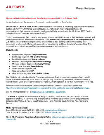
ensures adequate steam condensation on blowdown; i.e., no hot spots are generated inthe pool.Two vacuum breakers on each SRV discharge line serve to admit drywell atmosphereto the SRV discharge line. When the steam from the previously open SRV cools, anegative pressure is formed in the piping, drawing suppression pool water in to thedischarge piping. The vacuum breakers open to vent this negative pressure after anSRV opening cycle.Temperature and pressure elements are located in each SRV discharge tail pipe.These sensors will actuate an annunciator in the control room if the tail pipetemperature exceeds 220ºF or if the tail pipe pressure is 25 psig or greater. This alertsthe operator that an SRV is open or leaking.The Target Rock two stage pilot operated SRV, Figures 2.5.5 and 2.5.6, consists of twoprinciple assemblies: a pilot valve section and the main valve section. The pilot valvesection (first stage) provides the pressure sensing and control element while the mainvalve (second stage) provides the pressure relief function. The first stage provides themeans for remote actuation (ADS or manual) via the attached pneumatic actuator. Thepilot valve is the pressure sensing member to which the stabilizer disc movement iscoupled. The second stage consists of a large valve which includes the main valvedisc, main valve chamber, main valve preload spring, and piston. For operation of theSRVs refer to Section 2.5.4.2.2.5.3.4 Flow RestrictorsThe steam flow restrictors are a venturi type flow nozzle welded in each main steam linebetween the SRVs and the inboard MSIVs as shown in Figure 2.5-1. The flowrestrictors are designed to limit steam line flow in a severed line to approximately 200%of rated flow for that steam line. By limiting the rate of steam flow; the loss of coolantfrom the reactor vessel, the differential pressure across the reactor vessel internals, andthe rate of radioactivity release are limited.The flow restrictors also provide flow signals to the Feedwater Control System (Section3.3) and the Nuclear Steam Supply Shutoff System (Section 4.4). The flow restrictors,and the fast closure of the MSIVs, prevent uncovering the core and minimize theradioactive release following a steam line break.2.5.3.5 MSIVsEach main steam line contains two redundant MSIVs welded in the steam line pipe asclose as possible to the drywell penetration. The MSIVs, Figure 2.5-7, are "Y" pattern,pneumatic opening, spring and/or pneumatic closing valves designed to fail closed onloss of pneumatic pressure to the pneumatic actuator. The MSIVs are controlled by twosolenoid operated pilot valves. The dual solenoids (A and B) are redundant in functionRev 09/112.5-4USNRC HRTD
with either solenoid being capable of operating (opening) the valve. For reliability the Asolenoids are 120 VAC divisional power and the B solenoids use 125 VDC divisionalpower. Further reliability is obtained by separating the divisional power between theinboard and outboard MSIVs. The inboard MSIVs A solenoids get power from the 120VAC division 2 bus. The outboard MSIVs A solenoids get power from the 120 VACdivision 1 bus. A separate solenoid operated pilot valve with an independent test switchis included for a manual test of slow closure of each isolation valve from the controlroom.An accumulator, located close to each isolation valve, provides pneumatic pressure forthe purpose of assisting in valve closure when both pilots are de-energized or in theevent of failure of pneumatic supply pressure to the valves. The accumulator volume isadequate to provide full stroking of the valve through one-half cycle (open to close)when the pneumatic supply to the accumulator has failed. The supply line to theaccumulator is large enough to make up pressure to the accumulator at a rate fasterthan the valve operation bleeds pressure from the accumulator during valve opening orclosure.Each MSIV is equipped with position switches which provide open/closed indication tothe control room and a signal to the Reactor Protection System (Section 7.3) scram tripcircuit. To provide flexibility for testing, the MSIVs are arranged in the RPS logic, sothat one of the four steam lines can be isolated without requiring a full reactor scram,assuming reactor power is low enough to limit the resultant pressure and steam flowincrease.The MSIV pneumatic supply system, shown in Figures 2.5-8 and 2.5-9 is piped in sucha way that when one or both pilots are energized, the pneumatic actuator will open thevalve. When both pilots are de-energized, as in an automatic closure or manual switchin the closed position, the accumulator pressure is switched to pressurize the oppositeside of the pneumatic actuator and help the spring close the valve.Pressure from the accumulator or the spring force is capable of independently closingthe valve with the reactor vessel at full pressure. Thus, if one fails, the other shouldsuccessfully close the valve. The accumulator volume is adequate to provide fullstroking of the valve through one-half cycle (open to close) when supply air to theaccumulator has failed.The MSIV closure time of less than 5 seconds in conjunction with the steam line flowrestrictors, limits the release of radioactive materials to the environment and vesselinventory loss. MSIV closure times must be greater than 3 seconds. This allows timefor the RPS signal from the valve closure to initiate a reactor scram, minimizing thepower and pressure transient from the valve closure.Rev 09/112.5-5USNRC HRTD
The MSIVs are automatically closed upon receipt of any of the following isolationsignals from the Nuclear Steam Supply Shutoff system (Section 4.4):1. Reactor vessel low water level (Level 1).2. Main steam line high radiation.3. Main steam line high steam flow.4. Main steam line low pressure (in RUN mode).5. Main steam line area high temperature (Steam Tunnel).6. Main steam line area high temperature (Turbine Building).7. Main condenser low vacuum.8. Main steam tunnel high delta T.2.5.3.6 Steam Line DrainsA drain line, shown in Figure 2.5-4, is connected to the low point of each main steamline both inside and outside the drywell. These drains minimize water build up in thesteam lines by providing a path for this moisture to the main condenser. Thecontainment inboard and outboard steam line drains are used to equalize pressureacross the steam line isolation valves following main steam line isolation.2.5.3.7 Turbine Bypass ValvesThere are four (4) turbine bypass valves (BPVs), Figure 2.5-2, which are used to bypassup to 25% of rated steam flow directly to the condenser. The BPVs work in conjunctionwith the turbine control valves to ensure a constant reactor pressure for a given reactorpower level. Control or movement of the BPVs and turbine control valves isautomatically accomplished by the Electro Hydraulic Control (EHC) System (Section3.2).The BPVs are located in a multi valve manifold with main steam entering at both ends ofthe manifold to provide a balanced flow to all of the BPVs. The BPVs are a hydraulicoperated modulating valve, capable of controlling steam flow from zero to twenty-fivepercent of plant rated steam flow. During steam bypass operation (plant startup,shutdown, or transient conditions) the BPVs open sequentially.During a plant startup, heating and loading of the turbine are accomplished by firstestablishing a flow of steam to the condenser through the BPVs and then transferringthis flow to the turbine.During a normal shutdown, steam is released to the main condenser through the BPVsto achieve the desired rate of reactor cooldown.In the event of a turbine trip or load rejection bypass valves pass as much as 25 percentof the maximum turbine steam flow. This assists in minimizing the pressure andreactivity transient in the reactor vessel if the MSIVs are open.Rev 09/112.5-6USNRC HRTD
2.5.3.8 Turbine Stop ValvesThere are four Turbine Stop Valves (TSVs) located just upstream of the turbine controlvalves as illustrated on Figure 2.5-2. The TSVs are normally open during turbineoperation with a rapid closure capability, 0.1 seconds, upon detection of potentiallyunsafe turbine conditions. The four stop valves are equipped with a below seatequalizing header which is utilized during turbine startup operation. The #2 TSVcontains an internal bypass valve which is used for turbine warming prior to startup andequalizing the pressure across the stop valves prior to opening.If turbine load is greater than 30%, as sensed by first stage pressure, closure of theturbine stop valves, as sensed by the valve position limit switches, will produce areactor scram. The reactor scram ensures the fuel does not exceed the MCPR ThermalLimit resulting from the positive reactivity insertion created by the void collapse whenthe TSVs close.2.5.3.9 Turbine Control ValvesThe four turbine control valves are located between the TSVs and the turbine. Theturbine control valves regulate the steam flow to the turbine, as controlled by the EHCSystem, in order to control reactor pressure during normal operation. The controlvalves also provide the throttle mechanism for rolling, synchronizing, and loading theturbine generator.The control valves operate sequentially (partial arc) or in unison (full arc) via hydraulicfluid supplied from the EHC System. Each valve is equipped with a fast acting solenoidvalve which will dump the hydraulic fluid supply, and fast close the turbine control valvesin 0.2 seconds. To anticipate the resultant positive reactivity insertion created by thevoid collapse and protect the fuel cladding, the rapid control valve closure will cause areactor scram, if turbine load is greater than 30%, as sensed by first stage pressure.The scram signal originates from the hydraulic oil controlled by the fast acting solenoids.2.5.3.10 TurbineThe turbine is an 1800 rpm, tandem compound, four flow steam turbine, consisting ofone High Pressure (HP) and two Low Pressure (LP) turbines. Steam is from thereactor, to the TSVs, through four lines with a cross connection near the TSVs toequalize pressure, temperature and flow (Figure 2.5.2). The steam then flows throughthe TSVs to another equalizing header (steam chest) and then to the control valves.After passing through the control valves, the steam is directed to the center of the HPturbine where it flows to both ends. Some of the high pressure steam is redirected fromthe HP turbine to the 1st stage of reheat steam for the MSRs and to the 1st point (highpressure) feedwater heaters. The steam remaining after passing through the HPRev 09/112.5-7USNRC HRTD
turbine is exhausted to the moisture separator/reheaters which remove most of theentrained moisture and superheats the steam going to the LP turbines.After exiting the moisture separator/reheaters the steam enters the CombinedIntermediate Valves (CIVs) and then flows to the LP turbine casings. Steam enterseach of the LP turbines in the middle of the turbine and is directed from the center to thedual exhausts, at either end. Extraction steam is removed from the LP turbines tosupply the five low pressure feedwater heaters. This steam is removed symmetricallyfrom each LP turbine to prevent uneven axial loading of the shaft from any one turbineor turbine stage.Steam from the last stages of each LP turbine is exhausted to the main condenser viadual exhaust hoods. These exhaust hoods are maintained at a vacuum to ensuremaximum energy is extracted from the steam and to prevent condensation of the steamwhich would cause erosion of the last stage turbine blades. Steam not only supplies theenergy to move the turbine blades, but also provides a means to remove frictional heatfrom the turbine blades. At low steam flow rates, the last stages of the low pressureturbine can heat up causing the exhaust hood temperature to rise an excessive amount.To cool the exhaust hood, an exhaust hood spray system automatically controls thetemperature by spraying cool water from the condensate system on the hood (not ontothe rotating blades).Steam from the dual exhausts of the LP turbines is routed to the main condenser whereit is cooled and condensed by circulating water (flowing through the condenser tubes)and returned by the Condensate and Feedwater System to the reactor vessel.2.5.3.11 Moisture Separators/ReheatersThe moisture separator/reheaters, Figure 2.5-11, receive the exhaust steam from theHP turbine and remove about 98% of the moisture by passing the steam through aseries of chevron type baffle plates. Second Stage HP turbine extraction steam issupplied to a first stage of steam reheat. Main steam is supplied to the second stage ofthe moisture separator/reheaters to add superheat to the steam prior to entering the LPturbines.Condensate from the moisture separators drains into drain tanks, one for eachseparator, through the feedwater heaters and back to the condenser. The dried steamis piped through the combined intermediate valves, to the low pressure turbines. Arelief valve is installed in the steam line upstream of each Combined Intermediate Valve(CIV) to protect the low pressure piping if the CIVs should close and the turbine stopand control valves fail to close fully.Rev 09/112.5-8USNRC HRTD
2.5.3.12 Combined Intermediate ValvesThere are four CIVs (Figure 2.5.-2) that are located as close as possible to the lowpressure turbines. Each of these CIVs consists of an intercept valve and a stop valve,with both valves sharing a common seat. Both the intercept valve and the stop valvecan travel through full stroke regardless of the position of the other valve.The Stop valves are required on a turbine trip because the very large steam and waterinventory trapped in the piping between the HP and LP turbines and in the moistureseparator/reheaters could cause turbine overspeed. The intercept valves throttle steamflow to the LP turbines during overspeed conditions.The intermediate stop valves are not positioning units. They are either open or closedand act as emergency valves in the manner of the main stop valves.2.5.3.13 Steam Seal SystemThe steam seal system prevents the entrance of air and noncondensible gases into themain condenser while also preventing the leakage of radioactive steam to theatmosphere. Use of nonradioactive sealing steam enables gland exhaust air to beexhausted to the atmosphere rather than processed to remove radioactivecontamination.The Steam Seal Evaporator, Figure 2.5-12, produces non-radioactive steam by boilingdemineralized water using Third Point Extraction Steam or reduced pressure MainSteam as a heat source. The main Steam Seal header is maintained at about 4 psigby PCV-21, if the evaporator in not available for any reason the Steam Seal header canbe supplied by an Auxiliary Boiler. From the Main Turbine Steam Seal header, Figure2.5-13, a branch line supplies seal steam for the RFPTs and associated valves, Figure2.5-15.The steam seal leakoff is collected in the Gland Exhaust Header, Figure 2.5-13, whichis maintained at 10 in. water vacuum to ensure that no steam leaks into the TurbineBuilding atmosphere. One of two Steam Packing Exhauster Blowers pull the steam/airmixture in the Gland Exhaust Header through the Seal Steam Condenser where thesteam is condensed.Rev 09/112.5-9USNRC HRTD
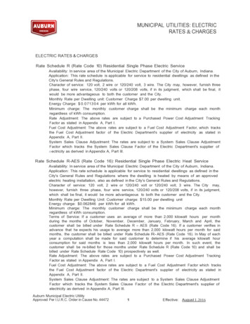
2.5.4 System Features and InterfacesA short discussion of system features and interfaces this system has with other plantsystems is given in the paragraphs which follow.2.5.4.1 Normal OperationDuring a unit startup, the MSIVs are open to allow the steam lines and equipment toheatup at the same rate as the reactor. The steam line drains are lined up to the maincondenser to aid in moisture removal from the steam lines.These drain paths are normally shifted to orificed lines after the main turbine has beenplaced in operation and significant steam flow is established through the main steamlines. When the steam line pressure increases above the EHC System pressuresetpoint the BPVs will open to pass steam to the main condenser as necessary tocontrol pressure.With the BPVs controlling reactor pressure, when sufficient steam flow exists to placethe turbine in operation, the turbine is warmed and loaded. When the turbine is loaded,the BPVs will close transferring pressure control to the turbine control valves. Asreactor pressure increases, the TCVs open to increase turbine load. At rated operatingconditions, reactor steam dome pressure is expected to be 1005 psig withapproximately a 55 psig pressure drop across the steam piping and valves, resulting ina pressure of approximately 950 psig at the turbine control valve inlet.2.5.4.2 Safety/Relief Valve OperationWhen the reactor is at operating pressure, below the setpoint of the SRV, the pilot valveis seated with system pressure acting on the stabilizer disc side (Figure 2.5-5). Thesecond stage of the SRV has system pressure on both sides of the main valve pistonwith the main valve disc seated and held closed by the main valve preload springs. Asthe system pressure increases to the SRV setpoint (Figure 2.5-6), the pressure actingon the pilot valve produces a force great enough to overcome the opposing force of thesetpoint adjustment spring thus lifting the pilot valve from its seat. As the pilot valvemoves to full open, the stabilizer disc follows the pilot until the stabilizer is seated. Withthe pilot valve full open and the stabilizer disc seated, the area above the main valvepiston is vented to the discharge piping via the main valve piston vent passage. Thisventing action creates a differential pressure across the main valve piston, systempressure below the piston and drywell pressure above, causing the main valve to open.The main valve piston is sized such that the resultant opening force is greater than thecombined spring load and hydraulic seating force. The stabilizer disc is designed tocontrol the valve blowdown and reset pressure, by holding the pilot open until the properreclosing pressure is reached. The stabilizer chamber is connected, by a passage, tothe inlet side of the main valve. The stabilizer disc will seat when the pilot lifts. Thedifferential pressure across the stabilizer disc is sufficient to hold the pilot open;however, as system pressure decays, the differential pressure across the stabilizer discRev 09/112.5-10USNRC HRTD
decreases until the setpoint adjustment spring becomes the controlling member causingthe pilot valve to reseat.Once the pilot valve has reseated, leakage of system fluid past the main valve pistonand the stabilizer disc re-pressurizes the main valve preload chamber. When steampressure equalizes across the main valve piston, the opening force is canceled andpermits the main valve preload spring and hydraulic flow to force the main valve closed.Once closed, the additional hydraulic seating force, due to system pressure acting onthe main valve disc, seats the main valve tightly and prevents leakage.In the manual mode of operation, pressure is applied to a pneumatic actuator (air ornitrogen) by energizing solenoid operated valves. The air actuator mechanicallypositions the pilot assembly to depressurize the top of the main valve piston causing themain valve to open. The solenoids are energized by switches located in the controlroom. This type of arrangement provides the control room operator with a means tooperate any of the 11 SRVs. Seven of the eleven SRV solenoids can also be energizedby actuation of the Automatic Depressurization System logic, (Section 10.2)2.5.4.3System InterfacesThe interfaces this system has with other plant systems are discussed in theparagraphs which follow.Reactor Vessel System (Section 2.1)The Main Steam System delivers steam from the reactor vessel to the various steamloads, vents noncondensible gases from the reactor vessel head area, and providesover pressure protection for the reactor vessel.Recirculation Flow Control System (Section 7.2)The Main Steam System provides a turbine first stage pressure signal to the arm theEnd of Cycle -Recirculation Pump Trip above 30% main turbine load.Reactor Protection System (Section 7.3)The Reactor Protection System uses the MSIV closure, TSV closure, and TCV fastclosure signals to initiate reactor scrams and preserve fuel cladding integrity.The Main Steam System provides a turbine first stage pressure signal to the arm theTSV closure and TCV fast closure scrams above 30% main turbine load (as sensed byfirst stage pressure).Rev 09/112.5-11USNRC HRTD
Condensate and Feedwater System (Section 2.6)The RFPTs use steam from the outlet of the moisture separator/reheaters and/or steamline equalizing header as an energy source.Extraction steam from the various main turbine high pressure and low pressure stagesis used to heat the feedwater before
Rev 09/11 2.5-ii USNRC HRTD LIST OF FIGURES 2.5-1 Main Steam System 2.5-2 Main Steam System (Cont.) 2.5-3 Auxiliary Steam Headers 2.5-4 Main Steam Line Drains 2.5-5 Two Stage Target Rock Safety/Relief Valve (Closed) 2.5-6 Two Stage Target Rock Safety/Relief Valve (Open) 2.5-7 Main Steam Isolation Valve