Transcription
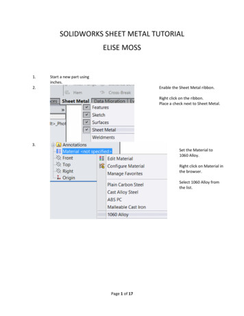
SOLIDWORKS SHEET METAL TUTORIALELISE MOSS1.2.Start a new part usinginches.Enable the Sheet Metal ribbon.Right click on the ribbon.Place a check next to Sheet Metal.3.Set the Material to1060 Alloy.Right click on Material inthe browser.Select 1060 Alloy fromthe list.Page 1 of 17
4.Start a New Sketch on the Top Plane.5.6.Draw a 5 x 7 inch rectangle centeredon the origin.On the Sheet Metal ribbon:Select Base Flange/Tab.Page 2 of 17
7.Set the thickness of the sheet metal to .0625 in.SolidWorks comes with gauge tables, but you need toset up a gauge table to use standard metalthicknesses.Select Green Check to complete.8.Select the Edge Flange tool.9.Set the Flange Length to 2.75 in.10.Select the two 7 in sides.Green Check to finish.11.12.Select the Edge Flange tool.3Set the Flange Length to 0.75 in.Page 3 of 17
13.Select the three edges of one end.Green Check to finish.14.15.16.17.Zoom in to inspect the mitered corners.Select the Edge Flange tool.Set the Flange Length to 1.5 in.Select the remaining edge.Green Check to finish.18.Locate the sketch for the last Edge Flange.Right click and select Edit Sketch.Page 4 of 17
19.Drag each side of the rectangletoward the center.Add a 0.50 inch dimension to eachside.Exit the Sketch.20.The flange is now offset on each side.21.Select the outside face of the offset flange.Start a new sketch on that face.22.23.Draw an arch shape with a radius of 0.5 and a height of0.5.Add a tangent constraint between the vertical lineand the arc to fully constrain the sketch.Page 5 of 17
24.25.Select Base Flange/Tab from the Sheet Metal ribbon.Verify that it is extruding in the correct direction and using thecorrect thickness.Green Check to finish.26.27.Select the Edge Flange tool.Set the Flange Length to 1.5 in.28.Select the top edge of the flange with the tab.Green Check to finish.Page 6 of 17
29.Select the new horizontal flange.Right click and select New Sketch.30.Draw a straight line the length of the flange.Dimension it to be 0.50 inches from the end.The endpoints of the line should be coincident to the edges ofthe flange.31.32.Select Sketched Bend from the Sheet Metal ribbon.Select the top face of the horizontal flange on the sidetoward the outside of the enclosure.Page 7 of 17
33.Set the Bend Angle to 30 deg.Green Check to finish.34.35.Inspect the resulting bend.On the Features ribbon:Select Chamfer.36.37.Add a .125 inch chamfer to the twocorners of the bend.Select the long side flange face.Right click and select New Sketch.Page 8 of 17
38.Draw two concentric circles.Locate the circles at 2.25, 1.5 from the origin.Circle 1 has a diameter of 1.5.Circle 2 has a diameter of 0.875.39.Draw a vertical lie bi-secting the circles.Create a circular pattern of the line with sixinstances.40.Select the Vent tool from the Sheet Metal ribbon.Page 9 of 17
41.Select the 1.5 diameter circle as the boundary.Left click inside the Ribs list box.Select the remaining circle and lines for the ribs.Set the rib thickness to 0.0625in.You should see a preview of the vent.Green Check to Finish.You have placed a fan vent.42.Select the side flange indicated for a new sketch.Page 10 of 17
43.Draw a line 0.40 from the outside edge.Be careful not to accidentally select the midpoint. If you do, deletethe constraint and then add the dimension.44.45.On the Sheet Metal ribbon:Select the Jog tool.Select the face towards the corner as tSet the Jog Offset to 0.120.Set the Jog Angle to 45deg.Green Check toFinish.46.47.On the Resource panel, locate the Sheetmetal folder underdesign library/features.Locate the sw-a152 feature.Page 11 of 17
48.Place on theoppositeflange/side wherethe fan ventopening wasplaced.Place a check onOverride dimensionvalues.Change R to 0.01.Change S to 0.06.Change A to 0.25.Click on GreenCheck.49.50.In the browser, locate the sketch under the sw-a152 feature.Right click to edit the sketch.Locate the sketch so it is 0.75 from the edge and 0.75 abovethe bottom of the enclosure.Exit the sketch to update.51.Highlight the sw-a152 feature in the browser.Page 12 of 17
52.53.Select Fill Pattern from the ribbon.Select the face where the feature is placed.Select staggered pattern.Set the spacing to 0.25.You should see a preview of the fill pattern.54.55.Green Check to accept.In the design library on the resources panel:Verify that the Forming Tools folder has been enabled as aForming Tools folder by right clicking on the folder.Page 13 of 17
56.57.58.59.Locate the louver feature in the louvers folder under formingtools.Place on the inside face next to the fan vent.Select the Position tab.Use the center line to position the feature 2.00 from the endof the flange and 1.00 below the top of the flange.Green check to place.60.Rotate the enclosure so you can inspect the louver.Page 14 of 17
61.Select the louver in the featurebrowser.Create a linear pattern of threeinstances 0.50 in apart.Green check to complete.62.63.Select the Unfold tool from the Sheet Metal ribbon.Select the bottom face as theFixed face.Click on Collect all Bends.Press Green Check.64.65.66.Select the main flat face for a new sketch.Place a 1.5 x 1.0 inch rectangle so it is crossing the bend.Select Extruded Cut from the Sheet Metal ribbon.Page 15 of 17
67.Place a check on Link to thickness.This ensures the cut will always be as thick as the sheet metalsetting.Green check to finish.68.Select Fold from the Sheet Metal ribbon.69.Click on Collect all Bends.Green check to finish.70.71.72.73.Notice how the cut goes through the bend.Save the part.Start a new drawing for the part.Place the standard views.Page 16 of 17
74.One of the views available is a flat pattern.Drag and drop it onto the sheet.75.To rotate the view:Select the view, then select Rotate from the Heads-Up displaytools.Page 17 of 17
SOLIDWORKS SHEET METAL TUTORIAL . ELISE MOSS . 1. Start a new part using inches. 2. Enable the Sheet Metal ribbon. Right click on the ribbon. Place a check next to Sheet Metal. . Select Sketched Bend from the Sheet Metal ribbon. 32. Select the top face of the horizontal flange on the side toward the outside of the enclosure. Page . 7. of . 17.
