Transcription
VLT 6000 HVAC Series ContentsIntroduction to HVAC. 4Software version . 4Safety regulations . 5Warning against unintended start . 5Introduction to the Design Guide . 6Available literature . 8Why use a frequency converter for controlling fans and pumps? . 8The clear advantage - energy savings . 8Example with varying flow over 1 year . 10Better regulation . 11Frequency converters generate less noise . 11Simpler installation when using a frequency converter . 11V-belts no longer required . 11Regulating dampers and valves no longer required . 11Cos ϕ compensation . 11Star/delta starter or soft-starter not required . 11Cost of using frequency converter not higher . 11Control principle . 13CE labelling . 14Application examples . 14Variable Air Volume . 15The new standard . 15Constant Air Volume . 16The new standard . 16Cooling Tower Fan . 17The new standard . 17Condenser pumps . 18The new standard . 18Primary pumps . 19The new standard . 19Secondary pumps . 20The new standard . 20Choice of frequency converter . 21Unpacking and ordering a VLT frequency converter . 25Type code ordering number string . 25Ordering form . 28PC software and serial communication . 29PC Software tools . 29Fieldbus options . 29Profibus . 29LON - Local Operating Network . 30DeviceNet . 30Modbus RTU . 30Installation.General technical data .Technical data, mains supply 3 x 200-240V .Technical data, mains supply 3 x 380-460V .Technical data, mains supply 3 x 525-600 V .Fuses .Mechanical dimensions .MG.60.B9.02 - VLT is a registered Danfoss trademark393943455053551
VLT 6000 HVAC SeriesMechanical installation .IP 00 VLT 6400-6550 380-460 V .General information about electrical installation .High voltage warning .Earthing .Cables .Screened/armoured cables .Extra protection with regard to indirect contact .RFI switch .High voltage test .Heat emission from VLT 6000 HVAC .Ventilation of integrated VLT 6000 HVAC .EMC correct electrical installation .Use of EMC-correct cables .Electrical installation - earthing of control cables .Electrical installation, enclosures .Tightening-up torque and screw sizes .Mains connection .Motor connection .Direction of motor rotation .Motor cables .Motor thermal protection .Earth connection .Installation of 24 Volt external DC supply .DC bus connection .High-voltage relay .Control card .Electrical installation, control cables .Switches 1-4 .Bus connection .Connection examples, VLT 6000 HVAC 0808081828283Programming. 85Control unit LCP . 85Control keys for parameter setup . 85Indicator lamps . 86Local control . 86Display mode . 87Navigation between display modes . 89Changing data . 90Manual initialisation . 90Quick Menu . 91Operation and Display 001-017 . 93The Setup configuration . 93Setup of user-defined readout . 94Load and Motor 100-117 . 100Configuration . 100Motor power factor (Cos ø) . 106Reference handling . 108Reference type . 111Inputs and outputs 300-328 . 116Analogue inputs . 119Analog/digital outputs . 122Relay outputs . 1252MG.60.B9.02 - VLT is a registered Danfoss trademark
VLT 6000 HVAC SeriesApplication functions 400-427 .Sleep mode .PID for process control .PID overview .Feedback handling .Serial communication for FC protocol .Protocols .Telegram communication .Telegram build-up under FC protocol .Data character (byte) .Process word .Control word according to FC protocol .Status word as per FC protocol .Serial communication reference .Present output frequency .Serial communication 500 - 556 .Extended status word, warning word, and alarm word .Service functions 600-631 .Electrical installation of the relay card .All about VLT 6000 HVAC.Status messages .List of warnings and alarms .Aggressive environments .Calculation of resulting reference .Galvanic isolation (PELV) .Earth leakage current .Extreme running conditions .Peak voltage on motor .Switching on the input .Acoustic noise .Derating for ambient temperature .Derating for air pressure .Derating for running at low speed .Derating for long motor cables or cables with larger cross-section .Derating for high switching frequency .Vibration and shock .Air humidity .Efficiency .Mains supply interference/harmonics .Power factor .EMC test results (Emission, Immunity) .EMC Immunity .Definitions .Parameter overview and factory settings 79179179179180180181182182184185187189. 196MG.60.B9.02 - VLT is a registered Danfoss trademark3
VLT 6000 HVAC SeriesVLT 6000 HVAC175ZA692.12 Software versionDesign GuideSoftware version: 2.6xThis Design Guide can be used for all VLT 6000 HVACfrequency converters with software version 2.6x.The software version number can be seen from parameter624.4MG.60.B9.02 - VLT is a registered Danfoss trademark
The voltage of the frequency converteris dangerous whenever the equipmentis connected to mains. Incorrectinstallation of the motor or the frequency convertermay cause damage to the equipment, seriouspersonal injury or death.Consequently, the instructions in this manual,as well as national and local rules and safetyregulations, must be complied with.6. Do not remove the plugs for the motor and mainssupply while the frequency converter is connectedto mains. Check that the mains supply has beendisconnected and that the necessary time haspassed before removing motor and mains plugs.7. Reliable galvanic isolation (PELV) is not compliedwith if the RFI switch is placed in OFF position.This means that all control in - and outputscan only be considered low-voltage terminalswith basic galvanic isolation.8. Please note that the frequency converter hasmore voltage inputs than L1, L2 and L3, whenthe DC-bus terminals are used.Check that all voltage inputs have beendisconnected and that the necessary time haspassed before repair work is commenced.Warning:Touching the electrical parts may be fatal - even after the equipmenthas been disconnected from mains.175HA490.11 Safety regulations1. The frequency converter must be disconnectedfrom mains if repair work is to be carried out. Checkthat the mains supply has been disconnectedand that the necessary time has passed beforeremoving motor and mains plugs.2. The [OFF/STOP] key on the control panel ofthe frequency converter does not disconnect Warning against unintended startthe equipment from mains and is thus not tobe used as a safety switch.1. The motor can be brought to a stop by3. Correct protective earthing of the equipmentmeans of digital commands, bus commands,must be established, the user must be protectedreferences or a local stop, while the frequencyagainst supply voltage, and the motor must beconverter is connected to mains.protected against overload in accordance withIf personal safety considerations make it necessaryapplicable national and local regulations.to ensure that no unintended start occurs, thesestop functions are not sufficient.4. The earth leakage currents are higher than 3.5 mA.2. While parameters are being changed, the5. Protection against motor overload is included inmotor may start. Consequently, the stop keythe factory setting. Parameter 117, Motor thermal[OFF/STOP] must always be activated, followingprotection default value is ETR trip 1.which data can be modified.Note: The function is initialised at 1.0 x ratedmotor current and rated motor frequency (see3. A motor that has been stopped may start if faultsparameter 117, Motor thermal protection).occur in the electronics of the frequency converter,or if a temporary overload or a fault in the supplymains or the motor connection ceases.Using VLT 6002 - 6005, 200-240 V: Wait at least 4 minutesUsing VLT 6006 - 6062, 200-240 V: Wait at least 15 minutesUsing VLT 6002 - 6005, 380-460 V: Wait at least 4 minutesUsing VLT 6006 - 6072, 380-460 V: Wait at least 15 minutesUsing VLT 6102 - 6352, 380-460 V: Wait at least 20 minutesUsing VLT 6400 - 6550, 380-460 V: Wait at least 15 minutesUsing VLT 6002 - 6006, 525-600 V: Wait at least 4 minutesUsing VLT 6008 - 6027, 525-600 V: Wait at least 15 minutesUsing VLT 6032 - 6275, 525-600 V: Wait at least 30 minutesMG.60.B9.02 - VLT is a registered Danfoss trademark5Introduction toHVACVLT 6000 HVAC Series
VLT 6000 HVAC Series Introduction to the Design GuideThis Design Guide is a tool intended to facilitate the sizing of systems in which VLT 6000 HVAC frequencyconverters are used.HVAC stands for Heating Ventilation Air-Conditioning.This Design Guide progresses step-by-step through the different procedures required for selecting, installingand programming a VLT 6000 HVAC.The Design Guide forms part of the literature concept supplied with VLT 6000 HVAC. However, the DesignGuide is the most comprehensive document available.When a VLT 6000 HVAC is supplied, it is accompanied by Operating Instructions and a Quick Setup Guide.See the section Other Literature.Operating Instructions:Describe how to ensure optimum mechanical and electrical installation,and also deal with commissioning and service. The Operating Instructionsfurthermore provide a description of the software parameters, thereby ensuringthat you can easily fit the VLT 6000 HVAC into your application.Quick Setup Guide:Helps you get your VLT 6000 HVAC installed and commissioned quickly.Design Guide:Used when designing systems with VLT 6000 HVAC. The Design Guide givesall useful information about the VLT 6000 HVAC and HVAC systems. There isa selection tool for you to choose the right VLT 6000 HVAC with the relevantoptions and modules. The Design Guide has examples of the most commontypes of HVAC applications. In addition, the Design Guide has all informationrelating to Serial Communication.This Design Guide is split in four sections that have information about VLT 6000 HVAC.Introduction to HVAC:This section tells you the advantages that can be obtained by using frequencyconverters in HVAC systems. Furthermore, you can read about the way afrequency converter operates and about the advantages of the VLT 6000HVAC, such as AEO - Automatic Energy Optimisation, RFI filter and otherHVAC-relevant functions.There are also examples of applications and information is given about Danfossand CE-labelling.The specification section deals with the requirements relating to being allowedto supply and install frequency converters. This section can be used incontract documents, whereby the total list of requirements relating to frequencyconverters is determined.The section ends with an Ordering Guide that makes it easier for you to specifyand order a VLT 6000 HVAC.6MG.60.B9.02 - VLT is a registered Danfoss trademark
VLT 6000 HVAC SeriesInstallation:This section shows you how to carry out correct mechanical installationof a VLT 6000 HVAC.In addition, the section has a description of how you ensure that theinstallation of the VLT 6000 HVAC is EMC-correct. Furthermore, the sectionincludes a list of mains and motor connections, as well as a description ofcontrol card terminals.Programming:This section describes the control unit and the software parameters for theVLT 6000 HVAC. There is also a guide to the Quick Setup menu, whichmeans that you will be able to start using your application very quickly.All about VLT 6000:This section has information about status, warning and fault indications fromthe VLT 6000 HVAC. In addition, the section has technical data, serviceinformation, factory settings and information on special conditions.Introduction toHVAC Introduction to the Design GuideNB!:This symbol indicates something to benoted by the reader.This symbol indicates a general warning.This symbol indicates a high-voltagewarning.MG.60.B9.02 - VLT is a registered Danfoss trademark7
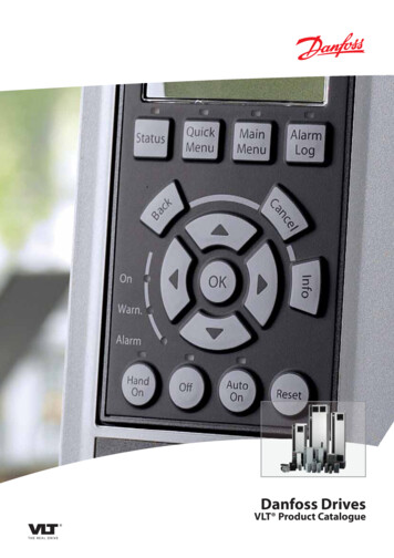
VLT 6000 HVAC Series Available literatureBelow is a list of the literature available for VLT6000 HVAC. It must be noted that there may bedeviations from one country to the next.Please also refer to our web site http://drives.danfoss.com for information about new literature.Supplied with the unit:Operating instructions . MG.60.AX.YYQuick Setup . MG.60.CX.YYCommunication with VLT 6000 HVAC:Software Dialog .Profibus Manual .Metasys N2 Manual .LonWorks Manual .Landis/Staefa Apogee FLN Manual .Modbus RTU Manual .DeviceNet Manual .GX.YYMG.10.SX.YYMG.50.HX.YYInstructions for VLT 6000 HVAC:LCP Remote Kit IP20 .LCP Remote Kit IP54 .LC-filter .IP20 terminal cover .RCD instructions .Relay card instructions .AX.YYMI.66.BX.YYVarious literature for VLT 6000 HVAC:Operating Instructions . MG.60.AX.YYData sheet . MD.60.AX.YYInstallation Guide . MG.56.AX.YYVLT 6000 HVAC Cascade Controller . MG.60.IX.YYX version number Why use a frequency converter for controllingfans and pumps?A frequency converter takes advantage of the factthat centrifugal fans and pumps follow the laws ofproportionality for such fans and pumps. The clear advantage - energy savingsThe very clear advantage of using a frequencyconverter for controlling the speed of fans or pumpslies in the electricity savings to be obtained.When comparing with alternative regulating systemsand technologies, a frequency converter is theoptimum energy control system for regulatingfan and pump systems.8YY language versionThe graph below describes the laws of proportionality.The graph shows that flow and pressure can beregulated by changing the rpm figure. Example of energy savingsAs can be seen from the figure (the laws ofproportionality), the flow is regulated by changingthe rpm figure. By reducing the speed only 20%from the rated speed, the flow is also reduced by20%. This is because the flow is directly proportionalMG.60.B9.02 - VLT is a registered Danfoss trademark
VLT 6000 HVAC Seriesto the rpm figure. The consumption of electricity,however, is reduced by 50%.If the system in question only needs to be able tosupply a flow that corresponds to 100% a few daysin a year, while the average is below 80% of therated flow for the remainder of the year, the amountof energy saved is even more than 50%.Introduction toHVACThe laws of proportionalityThis figure describes the dependence of flow, pressure and power consumption on the rpm figure.Q FlowQ1 Rated flowQ2 Reducing flowP PowerP1 Rated powerP2 Reducing powerH PressureH1 Rated pressureH2 Reducing pressuren Speed regulationn1 Rated speedn2 Reducing speedMG.60.B9.02 - VLT is a registered Danfoss trademark9
VLT 6000 HVAC Series Example with varying flow over 1 yearThe example below is calculated on the basis of pumpcharacteristics obtained from a pump datasheet.(45 kW). The same examples of calculations can beused in the case of fan characteristics.The result obtained is savings in excees of 50% at thegiven flow distribution over a year, correspondingto 8,760 hours.Typically, the example calculated below results in apay-back period of one year - depending on the priceper kWh and the price of the frequency co
a selection tool for you to choose the right VLT 6000 HVAC with the relevant options and modules. The Design Guide hasexamplesofthemostcommon types of HVAC applications. In addition, the Design Guide has all information relating to Serial Communication. This Design Guide is split in four sections that have information about VLT 6000 HVAC.