Transcription
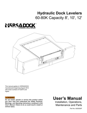
Hydraulic Dock Levelers60-80K Capacity 8', 10', 12'This manual applies to VERSADOCKmanufactured beginning August 2014with serial numbers 61122914 andhigher.Do not install, operate or service this product unlessyou have read and understand the Safety Practices,Warnings, and Operating Instructions contained in thisUser's Manual. Failure to do so could result in death orserious injury.User’s ManualInstallation, Operations,Maintenance and PartsPart No. 6003935F
TABLE OF CONTENTSIntroduction. 2Safety Signal Words. .2Safety Practices. 3Owner’s Responsibilities. 4Ramp And Lip Grades. 5Pit Layout. 6Installation. 6Service Tools . 13Components And Specifications . 14Hydraulic System Operation. 15Operating Instructions — Leveler. 16Planned Maintenance. 18Trouble Shooting Guide. 21Secondary Manifold Adjustment . 25Hydraulic Power Unit Adjustment . 26Hydraulic Schematic . 28Junction Box Electrical. 29Electrical Schematics. 30Auto Return to Dock — Operations. 40Auto Return to Dock — Adjustments. 41Parts List. 42Warranty Information. 59Distributor Information. 60INTRODUCTIONWelcome and thank you for buying this dock leveler from 4Front Engineered Solutions, Inc.This User’s Manual contains information that you need to safely install, operate and maintain the dock leveler andbumpers safely. It also contains a complete parts list and information about ordering replacement parts. Pleasekeep and read this User’s Manual before using your new dock leveler.SAFETY SIGNAL WORDSYou may find safety signal words such as DANGER, WARNING, CAUTION or NOTICE throughout this User’sManual. Their use is explained below:This is the safety alert symbol. It is usedto alert you to potential personal injuryhazards. Obey all safety messages thatfollow this symbol to avoid possible death or injury.Indicates an imminently hazardous situation which, ifnot avoided, will result in death or serious injury.Indicates a potentially hazardous situation which,if not avoided may result in minor or moderateinjury.Indicates a potentially hazardous situation which,if not avoided, could result in death or seriousinjury.Notice is used to address practices not related topersonal injury.2 2014 4Front Engineered Solutions, Inc.6003935F — 60-80K Hydraulic Dock LevelerAugust 2014
SAFETY PRACTICESOPERATION (continued)Read these Safety Practices before installing, operatingor servicing the dock leveler. Failure to follow the safetypractices could result in death or serious injury.If you do not understand the instructions, ask your supervisorto explain them to you or contact your local authorizeddistributor.OPERATIONUse restricted to trained operators.Follow procedures on placard posted near dock leveler.Do not use this unit to service vehicles outside its intendedworking range which is shown in the chart on page 5.Do not operate the dock leveler with equipment, material orpeople on the ramp or lip.Do not operate the dock leveler when anyone is in front of itunless they are securing the maintenance struts.Stay clear of the dock leveler when it is moving.Keep hands clear of hinges at all times. Do not use hands toposition dock leveler ramp or lip in vehicle or to store dockleveler.Stay clear of leveler unless lip supported by the vehiclebed or the ramp is supported by either both lip keepers atdock level or by both ramp stops at full below dock position;unsupported leveler can lower unexpectedly.Do not use a fork truck or other material handling equipmentto lower the ramp.Move all equipment, material or people off dock leveler andstore dock leveler at dock level before allowing the vehicleto pull out.Store dock leveler at dock level after use.Keep away from the dock leveler lip and bumpers when theraise button is pressed or released. The lip and dock levelerare free to move and the bumpers move automatically whenpressure is applied and/or released.INSTALLATION, MAINTENANCE AND SERVICEIf the dock leveler does not operate properly using theprocedures in this manual, call your local distributor forservice.Place barricades on the dock floor around the dock levelerpit and in the driveway in front of the pit while installing,maintaining or repairing the dock leveler.Do not operate the dock leveler when anyone is in front of itunless they are securing the maintenance struts.Do not work under the dock leveler ramp or lip unless bothmaintenance struts are securely supporting the leveler, andthe lip maintenance bar is supporting the lip.Disconnect the power supply and properly tag or lockout before climbing into the dock leveler pit or doing anymaintenance or repair under the dock leveler.Do not use the dock leveler if it appears damaged or doesnot operate properly. Inform your supervisor immediately.All electrical troubleshooting or repair must be done by aqualified technician and must meet applicable codes.Do not stand in the driveway between the dock leveler anda backing vehicle.Disconnect the power supply and properly tag or lock outbefore doing any electrical work.Before chocking wheels or engaging vehicle restraint, dumpair from air ride suspensions and set parking brakes.If it is necessary to make troubleshooting checks inside thecontrol box with the power on, USE EXTREME CAUTION!Do not place fingers or uninsulated tools inside the controlbox. Touching wires or other parts inside the control boxcould result in electrical shock, death or serious injury.Chock vehicle wheels or lock vehicle in place with avehicle restraining device and set brakes before loading orunloading.Ensure lip avoids contact with vehicle sides and cargo. If lipdoes not lower to vehicle bed, reposition vehicle.August 2014Keep away from the dock leveler lip and bumpers when theraise button is pressed or released. The lip and dock levelerare free to move and the bumpers move automatically whenpressure is applied and/or released.6003935F — 60-80K Hydraulic Dock Leveler 2014 4Front Engineered Solutions, Inc.3
SAFETY PRACTICES, continuedThe owner should recognize the inherent danger of theinterface between dock and transport vehicle. The ownershould, therefore, train and instruct operators in the safe useof dock leveling devices.When a transport vehicle is positioned as closely aspracticable to a dock leveling device, there shall be at least4" (100 mm) of overlap between the front edge of the lip andthe edge of the floor or sill of the transport vehicle.The owner shall see that all nameplates and caution andinstruction markings or labels are in place and legible andthat the appropriate operating and maintenance manualsare provided to users.Nameplates, cautions, instructions, and posted warnings shallnot be obscured from the view of operating or maintenancepersonnel for whom such warnings are intended.Manufacturer’s recommended periodic maintenance andinspection procedures in effect at date of shipment shall befollowed, and written records of the performance of theseprocedures should be kept.Dock leveling devices that are structurally damaged orhave experienced a sudden loss of support while underload, such as might occur when a transport vehicle is pulledout from under the dock leveling device, shall be removedfrom service, inspected by the manufacturer’s authorizedrepresentative, and repaired as needed before being placedback in service.Modifications or alterations of dock leveling devicesshall be made only with written permission of the originalmanufacturer.When industrial vehicles are driven on and off transportvehicles during the loading and unloading operation, thebrakes on the transport vehicle shall be applied and wheelchocks or positive restraints that provide the equivalentprotection of wheel chocks engaged.The dock leveler should never be used outside its verticalworking range or outside the manufacturer’s labeledrated capacity. It must also be compatible with the loadingequipment and other conditions relating to the dock.4 2014 4Front Engineered Solutions, Inc.6003935F — 60-80K Hydraulic Dock LevelerAugust 2014
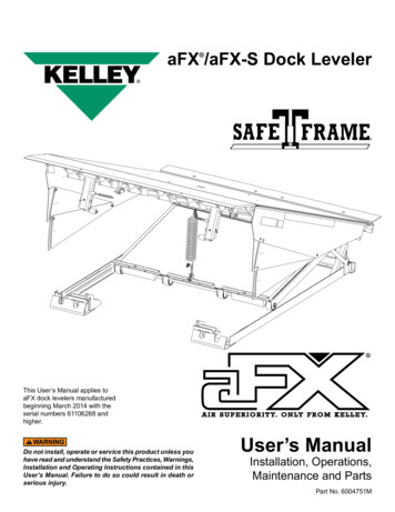
RAMP AND LIP GRADESFig. 1Ramp gradeLip gradeBelow DockAbove DockVehicle bedpositionfrom dock,(in.)Ramp and lip grades,% for each dock leveler length8' LevelerRampLip10' LevelerRampLip12' 18Ramp and lip grade, low lip bendAugust 20146003935F — 60-80K Hydraulic Dock Leveler 2014 4Front Engineered Solutions, Inc.5
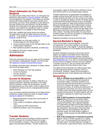
INSTALLATIONFig. 2PIT LAYOUT - Pit dimensions and curb angle lengths3"21"9"3/4" conduitfor electrical(high voltage)Rear curbangleassemblyControl panel(Inside wall)B1" Conduitfor electrical(low voltage)DACFace curbangle assemblyEmbed plate forvehicle restraint(flush with dockface)Front curbangle assembly(Optional)8"16"3/4" conduit forvehicle restraint(Optional)Anchor layout for curb angles3"4"9"9"Projected pit for slopeddrivewaysSee chart on next pagefor pit projection6 2014 4Front Engineered Solutions, Inc.4"45 1/4"Concrete anchors, 1/2" dia. x 6" long6003935F — 60-80K Hydraulic Dock LevelerAugust 2014
INSTALLATION, continuedPIT LAYOUT - continuedImportant - Concrete behind pit steel must be well vibrated.We recommend an 8" minimum thickness for pit walls, pitfloor, and dock face.Side curb angles must be 90 to dock face and to rear curb.*Pit projection guide for drive conditionsNotice: Driveway survey should be complete to determine grade and pit projection.Driveway Grade(In Percent)Pit Projection(In Inches)All angle joints to be welded securely.Consult the factory for dock heights under 42" or over 50".0% 1% 2% 3% 4% 5% 6% 7% 8% 9% 10%0"2"3"4"5"6"8"9" 10" 11" 12"Notice: Pit dimensional tolerances are 1/8" on squareness, depth, widthand length. 4Front Engineered Solutions, Inc. assumes no responsibilityfor deviations beyond these tolerances.Nominal Size (L x W)8' x 9'10' x 9'12' x 9'A(Pit Length)87"111"135"B(Pit Width)109"109"109"C(Front Depth)26"29"32"D(Rear Depth)25"28"31"Curb Angle Lengths(4 x 4" x 1/4" Angle)Quantity8' x 9'10' x 9'12' x 9'Side2Pit Length “A” - 4"Pit Length “A” - 4"Pit Length “A” - 4"Front Curb Angle Assy1Angle length “B” 8" see pit layout for concrete anchor spacingRear Curb Angle Assy1Angle length “B” 8" see pit layout for concrete anchor spacingFace Curb Angle Assy2Angle length “C” - 4" see pit layout for concrete anchor spacingAugust 20146003935F — 60-80K Hydraulic Dock Leveler 2014 4Front Engineered Solutions, Inc.7
INSTALLATION, continuedHYDRAULIC DOCK LEVELER INSTALLATIONINSTRUCTIONSFig. 3Before installing the dock leveler, read and follow theSafety Practices on page 3 and the Operating Instructionson pages 17-18. Failure to follow the safety practicesand instructions could result in death or serious injury.48"Push-buttoncontrol panelPIT CHECK1. Check entire dock leveler pit for proper constructionaccording to certified pit drawings. Check to be surethat the pit walls are square and plumb. Check electricalservice running to the control panel to assure it agreeswith the phase and voltage of the pump/motor and controlpanel supplied with the dock leveler. See tag attached tohydraulic power unit and wiring diagram located insidethe control panel.INSTALLATION OF DOCK LEVELERPlace barricades on the dock floor around the dockleveler pit and in the driveway in front of the pit whileinstalling, maintaining or repairing the dock leveler.Power to control box must be from fused disconnectsupplied by others. Fuse size for a dual element timedelay motor rated fuse can be no greater than 225%of motor FLA. Before doing any electrical work, makecertain the power is disconnected and properly taggedor locked out. All electrical work must be done by aqualified technician and must meet all applicable codes.If it is necessary to make troubleshooting checks insidethe control box with the power on, USE EXTREMECAUTION. Do not place fingers or uninsulated toolsinside the control box. Touching wires or other partsinside the control box could result in electrical shock,death or serious injury.1. Mount and wire control panel. See wiring diagram locatedinside the control panel. Follow the wiring instructions onthe wiring diagram. Run home run cables A and B fromthe control panel to the pit-mounted junction boxes. Runcables and wires through conduits indicated in Fig. 2.8 2014 4Front Engineered Solutions, Inc.Fig. 4 - Junction box located on leveler frame in pit. Seepages 14 and 27.J-box Ainput(to sensors)Home runcable A(to controlpanel)Motor powerJ-box6003935F — 60-80K Hydraulic Dock LevelerJ-box Boutput(to solenoids)Home run cable B(to control panel)August 2014
INSTALLATION, continuedFig. 5Shim to the back of pit wallInadequate lifting equipment or practices can cause aload to fall unexpectedly Make sure the lifting chain orother lifting devices are in good condition and have arated capacity of at least 8000 lbs for the lifting angleused. Never allow anyone to stand on or near the dockleveler when it is lifted or placed into the pit. Stand clearof the dock leveler when it is placed into the pit. Failureto follow this warning can allow the dock leveler to fall,tip or swing into people, resulting in death or seriousinjury.2. Hold the leveler closed with the bolt(s) through the lipplate and/or shipping banding securing the lip plate to theframe. Install four 3/4-10 load centering eye bolts (do notuse conventional 1 piece eyebolts) into the front and rearof the ramp (see Fig. 6) and hoist the leveler into the pit.The dock leveler should not be lifted in any other mannerwhen placing into the pit. See Fig. 6 and 7.3. Move the dock leveler back to the rear pit angle. With therear leveler angle touching the rear pit angle, square up thesides of the pit to the sides of the leveler. The gap shouldbe even on both sides. The rear frame angle should bewithin 1/8" on either sides of the pit curb angle. See Fig.8 and 9.4. Remove the bolt(s) and/or shipping banding from the lipplate.5. Use a chain or suitable lifting device to lift the levelerramp up and place the leveler ramp securely on bothmaintenance struts.August 2014Fig. 66003935F — 60-80K Hydraulic Dock Leveler 2014 4Front Engineered Solutions, Inc.9
INSTALLATION, continuedFig. 7Hydraulic pressure must be maintained on the ramp ora suitable lifting device needs to hold it in the raisedposition until the maintenance struts are securely inplace. DO NOT WORK UNDER THE DOCK LEVELERRAMP OR LIP UNLESS BOTH MAINTENANCE STRUTSARE SECURELY SUPPORTING THE LEVELER, ANDTHE LIP MAINTENANCE BAR IS SUPPORTING THE LIP.6. Using a pry bar, pry up the rear frame, one side at a time.Stack 4" x 4" steel shims of the appropriate thicknesscentered underneath each of the 7 rear hinge supportsand between the rear frame and the rear pit wall at eachof the positions shown in Fig. 5.Rear framedepthWeathersealsTelescopic toeguards retractedHold closedwith boltor metalbandingRear curb anglePit depthConduitentriesShims:4" x 4" x height7. Check the alignment of the top of the subframe and thetop of the rear pit curb angle. The top of the subframeshould be flush with the top of the rear pit curb angle. Ifa flush condition cannot be achieved, the frame shouldbe a maximum of 1/16" lower than the curb angle. Addor subtract shims as required.8. Place 4" x 4" steel shims of appropriate thickness betweenthe lifting cylinder mounting pads and the pit floor. Seepage 5.Before welding the rear frame, cover the weather sealswith a sheet of steel to prevent setting fire to the weatherseals. Failure to do so may result in property damage.Welding with the dock leveler’s power connected candamage electrical components. If the dock leveler haspreviously been electrically connected, turn off power tocontrol box before welding and disconnect the groundwire(s). Ground welder to dock leveler frame. Failure todo so may result in property damage.Fig. 8Pit side curb angleRamp1/2" - 1"1/2" - 1"Be certain that the rear frame is touching the rear pitcurb angle before welding.Note: At this point the electrician should complete thewiring between the control panel and the junction box.With electrical power available, return the leveler to thestored position.Rear pit curb angleRear frame angleShim the front end of the dock leveler LEVEL with therear frame of the leveler. If front and rear pit curb anglesare not parallel do not attempt to shim dock levelersupports to match pit angles. The lip keepers and lipplate must be parallel for proper operation of the dockleveler. Add or subtract shims as required. See Fig. 9and 10.10 2014 4Front Engineered Solutions, Inc.6003935F — 60-80K Hydraulic Dock LevelerAugust 2014
INSTALLATION, continuedFig. 9If the pit is out-of-square, the resulting gap between therear frame and the rear curb angle should be shimmedas necessary at the weld locations. Use steel shim(s)equal to the weld length and weld in place.Level with floor6" long welds centered overeach hinge (x7) and 3" weldsat each end of rear angle.See Fig. 9 and 10.Disconnect power and ground before welding.9. When the top of the rear frame has been leveledwith the rear pit curb angle, place 3" x 12" steelshims of the appropriate thickness underneath thefront of the leveler subframe and the maintenancestruts supports. These shims should be flush withthe front of the leveler frame, below or behind the lipkeepers. After verifying that both sides of the dockleveler are evenly spaced to the pit sides, finish weldthe rear frame angle to the pit rear curb angle. SeeFig. 9 and 5.10. Weld front of frame to shims, and shims to front curb anglewith 3" long welds on the front and sides of the shims.Shims must be welded in under the maintenance strutbrackets and lip keepers and between the back frameand pit back wall.Shim under lip keepers and maintenance postsFig. 10Front frame notparallel to rear frameIMPROPER INSTALLATION11. Weld rear hinge support shims together and to the dockleveler subframe under each rear hinge support. All weldsare to be 1" long minimum.12. Reconnect power and ground.PROPER INSTALLATIONFront frame parallel to rear frame,lip touching both lip keepersAugust 20146003935F — 60-80K Hydraulic Dock Leveler 2014 4Front Engineered Solutions, Inc.11
INSTALLATION, continuedFig. 11Keep away from the dock leveler lip and bumperswhen the raise button is pressed or released. The lipand dock leveler are free to move and the bumpersmove automatically when pressure is applied and/orreleased.12. Read Safety Practices on page 3 and OperatingInstructions on pages 16-17. With electrical poweravailable, use the controls to operate the dock levelerthrough the complete cycle to check operation. Ensurethe leveler operates properly.13. Using the electrical power use the procedure shown onpage 13 to place the leveler securely on both maintenancestruts.Removeshipping cotterpins14. Check shims under ramp cylinder mounting pads. Weldshims together and to subframe using 1" welds.15. Remove shipping cotter pins from telescopic toe guards(if equipped). See Fig. 11.Fig. 12Warning and operatinginstruction placard16. Permanently mount the laminated dock leveler safety andoperating instructions placard on the wall near the dockleveler controls. See Fig. 12. Make sure the customergets the user’s manual and is properly trained.17. Using the electrical power use the procedure shown onpage 13 to lower both maintenance struts.18. Operate the dock leveler four more times through thecomplete cycle to check operation.12 2014 4Front Engineered Solutions, Inc.6003935F — 60-80K Hydraulic Dock LevelerAugust 2014
SERVICE TOOLSFig. 13Before servicing the dock leveler, read and follow theSafety Practices on page 3 and the Operation section ofthis manual.DO NOT WORK UNDER THE DOCK LEVELER RAMPOR LIP UNLESS BOTH MAINTENANCE STRUTS ARESECURELY SUPPORTING THE LEVELER, AND THE LIPMAINTENANCE BAR IS SUPPORTING THE LIP.213MAINTENANCE STRUTS ANDLIP MAINTENANCE BAR1. To raise both maintenance struts and the lip maintenancebar two people are needed:a. Push and hold the RAISE button on the control panelso leveler is fully raised and lip is extended.b. The second person raises the maintenance strutsinto the locked vertical position while positioning themaintenance struts into the brackets located on theunderside of the ramp assembly. (See Fig. 13.)4Fig. 14c. Pull out hitch pin and clevis pin from top hole of lipmaintenance bar bracket and raise lip maintenancebar. (See Fig. 14.)d. Reinsert clevis pin through brackets and lipmaintenance bar bracket. Then reinsert the hitch pininto the clevis pin.e. Release the RAISE button and leveler will lowerto securely supported position resting on bothmaintenance struts.2. To lower both maintenance struts from its locked uprightposition two people are needed:a. Push and hold the RAISE button on the controlpanel.b. Pull out hitch pin and clevis pin from top hole on lipmaintenance bar bracket and lower lip maintenancebar.c. Reinsert clevis pin through brackets and then puthitch pin in clevis pin to store.d. Lift up and then push back to lower both maintenancestruts.e. Release the RAISE button.August 2014It is important to always engage the lip maintenancebar mechanism when ever working under the levelerwith the lip extended. Any upward force on the lip couldrelease the lip latch bar allowing the lip to fall.6003935F — 60-80K Hydraulic Dock Leveler 2014 4Front Engineered Solutions, Inc.13
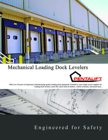
COMPONENTS AND SPECIFICATIONS(Dock Leveler)The main components of the leveler are shown below. See the Parts List for specific part numbers.Fig. 15Lip plateARTD sensorLip sensorLip stopLip hingeBumperTop plateLipmaintenancebarLip cylinderLip cylinderBumper cylinderBumper cylinderSafety stop (velocity fuse)Hydraulic power unitMaintenance strutLip keepers/ramp stopsMaintenance strutMain lift cylindersSubframeControl PanelFig. 16Leveler raiseLip extendStop14 2014 4Front Engineered Solutions, Inc.6003935F — 60-80K Hydraulic Dock LevelerAugust 2014
COMPONENTS AND SPECIFICATIONSControl Panel - NEMA 12, automatic motor starter, thermaloverload, 2 amp resettable control circuit breaker. U.L.approved.Auto Return to Dock Proximity Switch - NEMA IP68,normally open, with LED pilot light.Motor - NEMA Standard T.E.N.V. / 48YZ frame, 1 h.p., singleor three phase.Pump - Fixed displacement gear pump, 2 gpm, primary reliefvalve factory set at 1400 psi.Solenoid coils - 24 VAC, #8 series (1/2" dia.)I/O Wiring - Quick disconnect Euro. connectors, NEMA 6P,(IP-67)Reservoir Capacity - 1.3 U.S. gallons, (4.7 liters.) levelmeasured by dipstick.NOTE: Oil level should measure 4-1/2" 1/4" from the topof the fill hole with the leveler in maintenance position andthe lip extended.Hydraulic Fluid - Acceptable Hydraulic oils:Shell Tellus T 15Mobil Aero HFA (49011)Exxon Univis Grade J13Texaco Aircraft Oil #1554U.S. Oil Co., Inc #ZFI-5606 (Low Temp.)HYDRAULIC SYSTEM OPERATION(Leveler And Bumpers)The following describes the operation of the hydraulic system when the controls are activated.Fig. 17RAISE Pump starts, needle valve shifts. Bumpers Retract. Main lift cylinder extends and lip cylinder retracts. Pilot check valve opens.When Leveler Fully Raised Pressure Increases. Sequence valve shifts. Lip cylinder extends.RAISE Button Released Sequence valve and needle valve return. Leveler floats down forcing fluid into reservoir. Lowering speed controlled by flow control in needle valve. When ramp is supported by vehicle floor, bumpers extend.LIP EXTEND With leveler above dock height, pump starts as above. Solenoid valve (SV5) is de-energized, locking maincylinder inpartial raised position. Pressure increases, sequence valve shifts and lip extends.STOP Button Pressed Solenoid valve (SV5) is de-energized, locking main cylinderand lip cylinder. Power cut off from motor circuit.Communications light Light illuminates when power is applied to motor circuit. Light will flash when bumpers fail to engage.August 20146003935F — 60-80K Hydraulic Dock Leveler 2014 4Front Engineered Solutions, Inc.15
OPERATING INSTRUCTIONS — LEVELERBefore operating the dock leveler, read and follow theSafety Practices on page 3.Use by untrained people can result in death or seriousinjury. Read and follow complete operating instructions.DO NOT USE DOCK LEVELER IF IT LOOKS BROKEN, ORDOES NOT SEEM TO WORK RIGHT. Tell your supervisorit needs repair right away.Always be certain that the vehicle is properly restrained,before loading or unloading. VISUALLY INSPECTvehicle restraint to make sure vehicle does not pull awayunexpectedly. Failure to do so could result in death orserious injury.Never drive on dock leveler with STOP button pressedin.Always secure the vehicle with a vehicle restraint orwheel chocks before operating the dock leveler. Do notoperate the dock leveler with anyone standing on or infront of it.Always keep hands and feet clear of all moving parts.Always restore the dock leveler to its safe dock levelstorage position after servicing the vehicle.Keep away from the dock leveler lip and bumpers whenthe raise button is pressed or released. The lip anddock leveler are free to move and the bumpers moveautomatically when pressure is applied and/or released.Fig. 18Press to raiseRaiseRAISING LEVELER1. Press the RAISE button on control panel to retractbumpers and raise leveler.2. When the leveler is fully raised, the lip will automaticallyextend. To extend the lip earlier, press the LIP EXTENDbutton.3. When leveler is supported by vehicle floor, bumpers willextend.Fig. 19Lip extendPress toextend lipearlyIf amber pilot light is flashing, the bumpers have failedto extend properly. Reset by pressing RAISE or cyclingSTOP button.4. When lip is fully extended release the button. The levelerwill slowly float down to the vehicle bed, and the bumperswill extend when the lip is supported by the vehicle.Press the STOP button to stop leveler in any position.Never drive on the leveler with STOP button pressed.Leveler must be free to float with vehicle when driven on.Fig. 20Release to lowerFloat downIf an obstruction prevents the lip from extendingproperly, press the RAISE button to raise and retractthe lip. Perform below dock end loading as describedon page 18.16 2014 4Front Engineered Solutions, Inc.6003935F — 60-80K Hydraulic Dock LevelerAugust 2014
OPERATING INSTRUCTIONS, continuedSTORING LEVELER1. To return the leveler to the stored position, press theRAISE button. The bumpers will retract and the levelerwill raise. As the leveler raises the lip will retract. Whenthe lip is fully retracted, release the RAISE button. Theleveler will float down to the stored position. When theleveler is stored the bumpers will extend.Fig. 21Press to raiseRelease to lowerFig. 22Press to raisePress to extendIf the dock leveler is interlocked to a vehicle restraint thenthe bumpers will extend again when the vehicle restraintis released.BELOW DOCK END LOADING1. Press the RAISE button until leveler is about 6" abovedock. The bumpers will retract before the leveler starts toraise. Press LIP EXTEND button until the lip has clearedthe front of the keepers and release the button. Levelerwill float down for end loading.6"Float downLip extendAUTO RETURN TO DOCK (A.R.T.D.) OPERATIONSThe A.R.T.D. automatically resets the leveler whenever avehicle pulls away from the loading dock with the lip restingon the vehicle. This is how it works:1. If the vehicle pulls away, the leveler will float down to thelowest position and the lip will fall. The bumpers will retract.Then the leveler will automatically raise, retract the lip,then float down to the stored position. The bumpers willthen extend.Fig. 23August 20146003935F — 60-80K Hydraulic Dock Leveler 2014 4Front Engineered Solutions, Inc.17
PLANNED MAINTENANCETo ensure the continued reliable operation of your dockleveler, perform the following planned maintenanceprocedures.Before servicing the dock leveler, read and follow theSafety Practices on page 3 and the Operating Instructionsection in this manual.Place barricades on the dock floor around the dockleveler pit and in the driveway in front of the pit whileinstalling, maintaining or repairing the dock leveler.Be certain, before climbing into the pit or doing anymaintenance or repair under the leveler, that:1) Both maintenance struts are securely supporting theramp in the event it could fall or be accidently lowered.2) The power is disconnected and properly tagged orlocked off.Failure to do so could result in death, or serious injury.WEEKLYQUARTERLY (continued)1. Clean the upper portion of the lip plate hinge with a wirebrush and blow away all dirt and debris. This will ensureproper lip plate operation.3. Inspect and lubricate all mechanical pivot points on theleveler and bumpers wi
2 6003935F — 60-80K Hydraulic Dock Leveler August 2014 2014 4Front Engineered Solutions, Inc. INTRODUCTION Welcome and thank you for buying this dock leveler from 4Front Engineered Solutions, Inc. This User's Manual contains information that you need to safely install, operate and maintain the dock leveler and bumpers safely.