Transcription
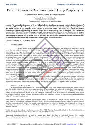
HydraulicPlus Model “HP”This User’s Manual applies todock levelers manufacturedbeginning March 2014 with theserial number 61106268 andhigher.Do not install, operate or service this product unless youhave read and understand the Safety Practices, Warnings,Installation and Operating Instructions contained in thisUser’s Manual. Failure to do so could result in death orserious injury.User’s ManualInstallation, Operations,Maintenance and PartsPart No. 6004750M
Table of contentsIntroduction.2Safety Signal Words.2Safety Practices.3Owner's Responsibilities.4Ramp and Lip Grades.5Installation.6Wiring Diagrams – Standard Control Box.15Wiring Diagrams – With Optional Interlock.17Wiring Diagrams With Optional Interlock AndAuto Return To Dock.21Operation– With Standard Control Box.25Operation – With Optional Auto Return To DockControl Box.28Planned Maintenance.31Service Tools.32Maintenance And Lubrication.33Troubleshooting Guide.35Hydraulic Diagram.39Parts Replacement.40Parts List.41Warranty.71Distributor Information.72IntroductionWelcome and thank you for choosing this dock leveler from Kelley . This dock leveler may be equipped withthe optional ENERGY GUARD dock leveler sealing system.This User’s Manual contains information that you need to safely install, operate and maintain the dock leveler. Italso contains a complete parts list and information about ordering replacement parts. Please keep and read thisUser’s Manual before using your new dock leveler.safety signal wordsYou may find safety signal words such as DANGER, WARNING, or CAUTION throughout this Owner’s Manual.Their use is explained below:This is the safety alert symbol. It is usedto alert you to potential personal injuryhazards. Obey all safety messages thatfollow this symbol to avoid possible death or injury.Indicates an imminently hazardous situation which, ifnot avoided, will result in death or serious injury.Indicates a potentially hazardous situation which,if not avoided may result in minor or moderateinjury.Indicates a potentially hazardous situation which,if not avoided, could result in death or seriousinjury.Notice is used to address practices not related topersonal injury.26004750M — HydraulicPlus Dock Leveler — SafeTFrame 2014 4Front Engineered Solutions, Inc.March 2014
Safety practicesRead these safety practices before installing, operatingor servicing the dock leveler. Failure to follow the safetypractices could result in death or serious injury.Do not use a fork truck or other material handling equipmentto lower the ramp.Before chocking wheels or engaging vehicle restraint, dumpair from air ride suspensions and set parking brakes.If you do not understand the instructions, ask your supervisorto explain them to you or call local Kelley distributor.Ensure lip avoids contact with vehicle sides and cargo. If lipdoes not lower to vehicle bed, reposition vehicle.OPERATIONINSTALLATION, MAINTENANCE AND SERVICEUse restricted to trained operators.Follow procedures on placard posted near dock leveler.Do not use this unit to service vehicles outside its intendedworking range which is 12 inches above and 12 inches belowdock. (18" above and 12" below dock on 10' models)Do not operate the dock leveler with equipment, material orpeople on the ramp or lip.Do not operate the dock leveler when anyone is in front of itunless they are securing the maintenance strut.Stay clear of the dock leveler when it is moving.Keep hands clear of hinges at all times. Do not use hands toposition dock leveler ramp or lip in vehicle or to store dockleveler.Do not use the dock leveler if it looks broken or does notseem to work right. Tell your supervisor it needs repair rightaway.Do not stand in the driveway between the dock leveler anda backing vehicle.Chock vehicle wheels or lock vehicle in place with avehicle restraining device and set brakes before loading orunloading.Place barricades on the dock floor around the dock levelerpit and in the driveway in front of the pit while installing,maintaining or repairing the dock leveler.Do not operate the dock leveler when anyone is in front of itunless they are securing the maintenance strut.PUT AND PIN MAINTENANCE STRUT IN PLACE ANDMAKE SURE LIP LOCK IS IN PLACE AND SUPPORTINGTHE LIP before climbing into the dock leveler pit or doingany maintenance or repair under the dock leveler.Disconnect the power and properly tag or lock off beforeclimbing into the dock leveler pit or doing any maintenanceor repair under the dock leveler.All electrical troubleshooting or repair must be done by aqualified technician and must meet applicable codes.Disconnect the power and properly tag or lock off beforedoing any electrical work.If it is necessary to make troubleshooting checks inside thecontrol box with the power on, USE EXTREME CAUTION!Do not place fingers or uninsulated tools inside the controlbox. Touching wires or other parts inside the control boxcould result in electrical shock, death or serious injury.Stay clear of leveler unless lip supported by the vehicle bedor the ramp is supported by both front dock level supports;unsupported leveler can lower unexpectedly.Store dock leveler at dock level after below dock endloading.Move all equipment, material or people off dock leveler andstore dock leveler at dock level before allowing the vehicleto pull out.March 20146004750M — HydraulicPlus Dock Leveler — SafeTFrame 2014 4Front Engineered Solutions, Inc.3
Owner’s responsibilitiesThe owner’s responsibilities include the following:The owner should recognize the inherent danger of theinterface between dock and transport vehicle. The ownershould, therefore, train and instruct operators in the safe useof dock leveling devices.When a transport vehicle is positioned as closely aspracticable to a dock leveling device, there shall be at least4" of overlap between the front edge of the lip and the edgeof the floor or sill of the transport vehicle.Nameplates, cautions, instructions and posted warnings shallnot be obscured from the view of operating or maintenancepersonnel for whom such warnings are intended.Manufacturer’s recommended periodic maintenance andinspection procedures in effect at date of shipment shall befollowed, and written records of the performance of theseprocedures should be kept.Dock leveling devices that are structurally damaged orhave experienced a sudden loss of support while underload, such as might occur when a transport vehicle is pulledout from under the dock leveling device, shall be removedfrom service, inspected by the manufacturer’s authorizedrepresentative, and repaired as needed before being placedback in service.The owner shall see that all nameplates, caution andinstruction markings or labels are in place and legible andthat the appropriate operating and maintenance manualsare provided to users.Modifications or alterations of dock leveling devicesshall be made only with written permission of the originalmanufacturer.When industrial vehicles are driven on and off transportvehicles during the loading and unloading operation, thebrakes on the transport vehicle shall be applied and wheelchocks or positive restraints that provide the equivalentprotection of wheel chocks engaged.The dock leveler should never be used outside its verticalworking range or vertical lifting range or outside themanufacturer’s labeled rated capacity. It must also becompatible with the loading equipment and other conditionsrelating to the dock.46004750M — HydraulicPlus Dock Leveler — SafeTFrame 2014 4Front Engineered Solutions, Inc.March 2014
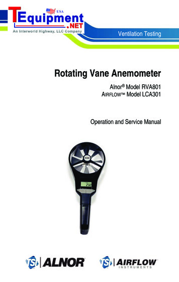
Ramp and lip gradesFig. 1Ramp gradeLip gradeRAMPLIPRAMPLIPRAMPLIPVehicle bedpositionfrom .5-18.6RAMP and LIP grades, % for each Dock Leveler length4 lip bend, 16" lip.March 20148' Leveler10' LevelerRAMP and LIP grades, % for each Dock Leveler length6' Leveler8' Leveler10' e dock6' LevelerBelow dockBelow dockAbove dockVehicle bedpositionfrom dock,(in.)7 lip bend, 16" lip (Optional special order)6004750M — HydraulicPlus Dock Leveler — SafeTFrame 2014 4Front Engineered Solutions, Inc.5
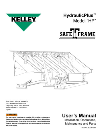
InstallationPIT CHECK1. Check entire dock leveler pit for proper constructionaccording to certified pit drawings (publication 5568).Check to be sure that the pit walls are square and plumb.Check electrical service running to the pit to assureit agrees with the correct location and voltage for thejunction box. Area surrounding the leveling feet shouldbe smooth and free of excessive lumps. Inspect thepit and remove all loose trash and construction debris.Verify the pit matches pit details for your leveler. See theinstallation troubleshooting on page 14 if the pit variesfrom the specification.leveler check prior to installation1. Visually check that the 4 rear hinge pins and retainingclips are in place.1. The control station, User’s Manual and dock bumpersare attached to the sub frame of the dock leveler. Themaintenance strut has a plastic tie wrap holding themto the subframe. Remove these items before placingthe leveler into the pit. Make sure the customer gets theuser’s manual and is properly trained.2. Mount and wire push-button control station (See Fig.2) and pit mounted receptacle.See Fig. 3. See wiringdiagram located on the inside cover of the control box orwiring diagrams on pages 15-24 of this manual for wiringinformation. Follow the wiring instructions to set controlfor proper voltage. Wires shown in dashed lines are fieldconnections.3. Visually check that cotter pins are in place on pins on theconnecting rod, push bar, and the lip lifter assembly.3. If conduit must be installed (replacing an existingmechanical dock leveler) do so at this time. Refer to theconduit requirements on the pit detail publications 5568and powered dock leveler wiring diagrams and typicalinstallation drawings, and powered dock leveler wiringdiagrams on pages 15-24 for electrical requirements.Follow all applicable electrical codes and standards.4. Verify that gas spring retaining pins have cotter pinsinstalled.Fig. 22. Visually check that the lip shaft collars or shaft retainersare in place on both lip rods.5. Verify that both the lip lock and the maintenance strutare undamaged and have safety hitch pins on chains.6. Visually check that the foot assemblies at the rear of theleveler are in place and undamaged.48"prepare sitePush-buttoncontrol stationPlace barricades around pit on dock floor and drive whileinstalling, maintaining or repairing dock leveler.Power to control box must be from fused disconnectsupplied by others. For correct fuse size refer to wiringdiagrams on pages 15-24 of this manual. Fuses to beclass CC time delay. Before doing any electrical work,make certain the power is disconnected and properlytagged or locked off. All electrical work must be doneby a qualified technician and must meet all applicablecodes. If it is necessary to make troubleshooting checksinside the control box with the power on, USE EXTREMECAUTION. Do not place fingers or uninsulated tools insidethe control box. Touching wires or other parts inside thecontrol box could cause electrical shock, resulting indeath or serious injury.6Fig. 3Pitcenterline 10"12"-13"Box located asshown6004750M — HydraulicPlus Dock Leveler — SafeTFrame 2014 4Front Engineered Solutions, Inc.March 2014
Installation, continuedFig. 4Before installing the dock leveler, read and follow theSafety Practices on page 3. Failure to follow the SafetyPractices could result in death or serious injury.installation of dock leveler6' and 8' long levelers using a standard 19" subframe canbe field converted to allow installation in a 24" pit by addinga 4" riser kit, Kelley Part No. 6004654. Install the new riserleveling feet. The riser blocks should be welded to the frontframe supports prior to placing in the pit. See publication#6003728 and page 45 in this manual.1. Prior to lifting leveler make sure the shipping tie downbolts seen in Fig. 14 are in place. Install two 3/4”-10UNCload centering eye bolts into the front and rear of the topplate and hoist leveler into pit. The dock leveler shouldnot be lifted in any other manner when place into the pit.See Fig. 4.Inadequate lifting equipment or practices can cause aload to fall unexpectedly. Make sure the lifting chain orother lifting devices are in good condition and have arated capacity of at least 3500 lbs for the lifting angleused. Never allow anyone to stand on or near the dockleveler when it is lifted or placed into the pit. Stand clearof the dock leveler when it is placed into the pit. Failureto follow this warning can allow the dock leveler to fall,tip, or swing into people, resulting in death or seriousinjury.3/4" - 10 UNCload centeringeyeboltFig. 5Route power cord clear of edges and resting surfacesso that it is not damaged during lifting and placement.Plug end may be routed up through the rear hinge untilneeded.March 20146004750M — HydraulicPlus Dock Leveler — SafeTFrame 2014 4Front Engineered Solutions, Inc.7
Installation, continuedinserting the leveler into the pit2. Position dock leveler in pit about 7" away from therear pit wall. Connect plug to receptacle on the rear pitwall. Cut tie wrap on cord to allow bag pan removal forservice. Place the free length of cord inside of framearea, free of interference as the leveler is moved into thefinal position. See Fig. 5 and wiring diagrams on pages15-24.NOTE:Check the pit floor for uneven or excess concrete in the areaaround the leveling feet 1"-6" from the rear wall. Use chiselto level out area if necessary.Turn off all electrical power to the leveler if it has beenpreviously connected. Welding with dock levelers powerconnected can damage the electrical components. Aground must be attached to the leveler frame. Failure todo so can result in product damage.Fig. 63. Move the dock leveler back to the rear pit curb angle.See Fig. 6. With the rear leveler angle touching the rearpit angle, square up the sides of the pit to the sides ofthe leveler. The gap should be even on both sides. Therear frame angle should be within 1/4" on either sides ofthe pit curb angle.NOTE:The rear frame angle should be about 1/2" lower than the pitcurb angle before leveling. This is normal. See Fig. 7.leveling the rear frame4. Using a 1/2" square drive (1/2" ratchet or impact tool)work from one side to the other, turn each of the levelingscrews on the rear angle, counter-clockwise until thetransition angle of the rear angle is level with the rear pitcurb angle and the leveling screws are 1/4" from the toptransition angle which indicates that legs are in contactwith pit floor. Repeat on each leg until the transitionangle is flush with the rear curb angle. See Fig 8.Fig. 71/2"The rear edge of the dock leveler should be level orslightly (1/16" maximum) below dock level.The top surface of the dock leveler should be level and asmooth transition with the dock floor curb steel. The frontend should be level and parallel with the rear frame anglefor proper operation. Unequal adjustment of the frontsupports may be required to obtain a level front edge.1/2"86004750M — HydraulicPlus Dock Leveler — SafeTFrame 2014 4Front Engineered Solutions, Inc.March 2014
Installation, continued5. Check and adjust the leveler for square and in firmcontact with the rear angle. The sides of the levelershould have a 1/2" gap and parallel with the sides of thepit. Tack weld the rear angle to the rear curb angle in 4places min 3/8" at the center and at both ends. See Fig.9 and 10.Fig. 8Transition angleCurbangleRaisesrearangleNOTE:Do not weld out the rear angle until after setting the frontsupports.leveling the FRONT frame1/4"6. Remove and discard the shipping tie down bolts locatedat the lower end of the hinged lip assembly. See Fig.14.Before welding the dock leveler supports to the frontcurb angle make sure that the dock leveler support legsline up with the “V” pocket in the dock leveler supportangle. Move dock levelers support right or left for thenecessary alignment.Legs are in contactwith pit floor whenthe leveling screwsare 1/4" from thetop of the transitionangleLegadjustment7. Tack weld the front dock leveler supports to the front curbangle. See Fig. 12.8. With the lip pendant insert 24" long 1/2" extensionsbetween lip and lip rod onto dock leveler support levelingscrew. See Fig. 12. Using a 1/2" drive (1/2" ratchet orimpact tool) turn each leveling screw counter-clockwiseuntil the top of the leveler is flush with the finished floor/pit curb steel where the overhead door meets the floor.See Fig. 11.finish welding rear frame9. Weld the rear frame angle to the rear curb angle using1/4" bevel joints in the transition angle as your guide.See Fig. 10.10. After the rear hinge is welded check that all rear levelinglegs are in contact with the floor of the pit by visuallyinspecting that the leveling screws are 1/4" from the topof the transition angle. Once all legs are in contact withfloor, tighten each leg leveling screw counter-clockwiseto 25-40 ft. lbs.Fig. 9Rear pitcurb angleRearframeangle1/2"1/2"RampPit side curb angleFig. 10Bevel groove weld rightsMarch 20145"PitrearcurbangleRear hingeassembly6004750M — HydraulicPlus Dock Leveler — SafeTFrame 2014 4Front Engineered Solutions, Inc.9
Installation, continued11. If a field installed riser kit is being used, do not usehydraulics to position leveler on maintenance strut beforecylinder support riser is in place. Use a suitable liftingdevice to place leveler on maintenance strut per step12 below, then position and weld in the cylinder supportbracket. If electrical power is available, reconnect powerand use the electrical controls to raise the ramp and lip totheir full above dock position. See operating instructionson front cover of control box. If electrical power in notavailable, raise ramp using a chain or other suitablelifting device.Fig. 11Hydraulic pressure or mechanical support must bemaintained on the ramp to hold it in the raised positionuntil the maintenance strut is in place. DO NOT WORKUNDER THE DOCK LEVELER RAMP OR LIP UNLESSTHE MAINTENANCE STRUT IS IN PLACE AND PINNED,AND LIP LOCK IS IN PLACE AND SUPPORTING THE LIP.Fig. 1212. Two people are needed to place the dock leveler on themaintenance strut.a. One person must hold dock leveler in its highestposition with electrical controls or other suitablelifting device.b. The second person positions the mintenance strutinto the bracket located on the underside of theramp assembly and pins it in place with hairpin clip.See Fig. 15 and instruction label on maintenancestrut.c. Electrical controls may now be released.Door jambFlush with floor at this point1/2" sq. driveadjustment boltCCW rotationto raise3/16" weld(both sides)3/16" weld3/16" weld3" long (min.)3/16" weld3" long (min.)(both sides)Curb steel3/16" weld(both sides)3/16" weld3" long (min.)(both sides)Curb steel3/16" weld3" long (min.)13. 6x16" shims of the proper thickness are to be placedunder the ramp cylinder mounting pad and welded outas shown in Fig. 13.Fig. 133/4"anchorbolt(suppliedby others)10Cylindermounting pad Stagger and weld6" x 12" shims6004750M — HydraulicPlus Dock Leveler — SafeTFrame 2014 4Front Engineered Solutions, Inc.March 2014
Installation, continuedFig. 14Manual support of the lip must be maintained until the liplock is in place. The lip is free to move downward whenit is released unless the lip lock is in position supportingthe lip. DO NOT WORK UNDER THE DOCK LEVELERRAMP OR LIP UNLESS THE MAINTENANCE STRUT IS INPLACE AND PINNED, AND LIP LOCK IS IN PLACE ANDSUPPORTING THE LIP.14. To engage lip lock, manually lift lip to fully raised position.Pull lip lock outward as far as it will go. Release lip lock.Slowly lower lip onto lip lock. See instruction label ondock leveler beam near lip lock.Welding with the dock levelers power connected candamage electrical components. If the dock leveler hasbeen previously connected, turn off power to controlbox and unplug all electrical cords from receptacles inrear pit wall before welding. Failure to do so can resultin product damage.15. Finish welding both of the adjusted front dock levelersupports in all locations shown in Fig. 12.Shipping tiedown boltFig. 15Insert hairpinclip throughmaintenancestrut pinLipLiplockMaintenancestrut pinMaintenancestrutMaintenancestrut bracket16. Check shims under ramp cylinder pad. Adjust thicknessif necessary.Improper installation of anchoring devices or installationinto aged or unsound concrete could result in death orserious injury.17. Drill and install 3/4" diameter anchor bolts (min. 3" deep)in ramp cylinder mounting pad. Weld shims to pad asnoted in Fig 13.18. Remove and discard shipping cotter pins from toeguards on both sides of dock leveler. See Fig. 16.Fig. 1619. Remove lifting chain or other lifting devices. Removelifting hooks from the sides of the ramp.20. Read the Safety Practices on page 3, and the OperationInstructions on pages 25 through 30 before operatingthe dock leveler.Removeshipping cotterpinsMarch 20146004750M — HydraulicPlus Dock Leveler — SafeTFrame 2014 4Front Engineered Solutions, Inc.11
installation, continuedFig. 17Improper installation of anchoring devices or installationinto aged or unsound concrete could result in death orserious injury.Molded "L" bumpers1" Dia.4"3"The dock face must be flush with curb angle to assureproper bumper mounting.21. Mount dock bumpers to face of dock. Downhill welds areunacceptable. See Fig. 17 or 18.J bolts (3) per bumperfurnished by KelleyCompany, Inc. locateand weld to curbangle at time ofbumper installation.22. Plug or wire in electrical cords and connect power todock leveler.Manually support the lip when storing the lip lock. Standclear of the lip when removing support. The lip is free tomove downward when support is removed. Anyone in thepath of the lip when it moves downward can be struck.Keep your hands, fingers and head away from the lipwhen it is released. They could be struck by the lip orcaught between the lip and other parts of the dock levelerresulting in death or serious injury.DO NOT REMOVE MAINTENANCE STRUT WITHOUTHYDRAULIC PRESSURE OR A MECHANICAL LIFTINGDEVICE SUPPORTING RAMP. Raise ramp withhydraulic pressure or mechanical device before storingmaintenance strut. Stand clear of ramp and lip whenhydraulic pressure or mechanical lift is applied orremoved. Ramp and lip are free to move downwardwhen support is removed. Removing support withouthydraulic pressure could allow ramp to drop RAPIDLY. Ifthe dock leveler was raised using a mechanical device,it should be lowered using the same device.Fig. 18Laminated bumpers3/8" side of pitto side of bumpermounting plate1/4"Full length of bumpermounting plate.downhill welds ions must beinstalled verticallyTocurbangle1/4"3/4" dia.anchor bolt.field installed.supplied byothers.23. Lift lip completely. Push lip lock inward as far as it willgo. Slowly lower lip. See instruction label on dock levelerbeam near lip lock.24. Two people are needed to store the maintenance strut.a. One person must push and hold the raise buttonuntil dock leveler reaches its highest position andhold dock leveler in its highest position.126004750M — HydraulicPlus Dock Leveler — SafeTFrame 2014 4Front Engineered Solutions, Inc.March 2014
installation, continuedb. The second person unpins the maintenance strutfrom the bracket on the ramp and stores it on thesubframe. See Fig. 15 and the instruction label onmaintenance strutc.Fig. 19OPERATWarning and operatinginstruction placardIONSThe raise button may now be released. The rampwill lower and the lip will extend when the button isreleased.The hinged lip will extend as the ramp moves down.25. Place the dock leveler in both dock leveler storageposition and full below dock end load position. If lip isbeing supported by the curb steel in either position, adeflector plate must be created to allow leveler to storeand reach its full below dock position without gettinghung up on the pit floor.Improper installation that allows the pendant dock levelerlip to support the weight of the dock leveler could resultin death or serious injury. It is sometimes necessary toinstall lip deflector plates to avoid any chance of thependant lip supporting the weight of the dock levelereither near dock level or during a below dock end load.Fig. 20Rear angleCap plug26. Permanently mount the laminated dock levelerWARNING and OPERATING instruction placard on thewall near the dock leveler control. See Fig. 19. Makesure the customer gets the user’s manual and is properlytrained. Make sure customer gets user's manual and isproperly trained.27. Operate the dock leveler four times through the completecycle to check operation. (See Operation section, page25.)NOTE:If you have any problems or questions using or operatingthe dock leveler, contact your supervisor or local Kelley distributor for assistance.28. Optional (where applicable), install rear angle cap plugs(part number 6004488) into adjustment socket holes.Press cap flush with top surface to rear angle. See Fig.20.March 20146004750M — HydraulicPlus Dock Leveler — SafeTFrame 2014 4Front Engineered Solutions, Inc.13
installation, continuedinstallation troubleshootingThe following procedures apply after the leveler is level inthe pit.PROBLEMPOSSIBLE CAUSE1) Leveler will not fit properly in pit.a) Pit is out of square with the sides.a) Align the sides parallel and equallyspaced with the rear frame angletouching the rear curb angle in oneplace. Fill the gap between the rearcurb angle and rear frame angle usingshims in weld pattern noted in Fig. 10.See Fig 21.b) One side and rear angle is out ofsquare.b) Align the leveler with the two squareedges. The gap on the sides shouldbe even in the most narrow section(1/2" Max. per side). See Fig. 22.c) Pit floor irregular in rear.c) If large deformations exist in theconcrete work, attempt to flattenout the rough surface using a chiselor grinder to take out the largeobstructions. The rear leveling legscan be installed on out of planesurfaces up to 1/8" at each leg. SeeFig. 23.d) Pit is too deep.d) Weld 4" x 4" shims to the bottom ofthe adjustable legs.Fig. 22Fig. 21SOLUTIONFig. 23Shim and weld flushEqualgap1/2" max.1/8" maxallowable stepno greater than1" x 3" in size6"contactzone146004750M — HydraulicPlus Dock Leveler — SafeTFrame 2014 4Front Engineered Solutions, Inc.March 2014
Wiring diagrams — control box — standardBefore doing any electrical work, make certain the poweris disconnected and properly tagged or locked off. Allelectrical work must be done by a qualified technicianand meet all applicable codes. If it is necessary to maketroubleshooting checks inside the control box withthe power on, USE EXTREME CAUTION. Do not placeyour fingers or uninsulated tools inside the control box.Touching wires or other parts inside the control boxcould result in electrical shock, death or serious injury.NOTE:For 24V incoming power consult factory.6006461 — 120V, 1 PH, 50/60 Hz6006462 — 208-240V, 1 PH, 60 HzMarch 20146004750M — HydraulicPlus Dock Leveler — SafeTFrame 2014 4Front Engineered Solutions, Inc.15
Wiring diagrams — standard6006450 — 208-230V, 3PH, 50/60 Hz6006451 — 460-480V, 3PH, 60 Hz166004750M — HydraulicPlus Dock Leveler — SafeTFrame 2014 4Front Engineered Solutions, Inc.March 2014
Wiring diagrams — standard, continued6006452 — 575V, 3PH, 60 HzWiring diagrams with interlock6011372 — 120V, 1ph, 60 hzMarch 20146004750M — HydraulicPlus Dock Leveler — SafeTFrame 2014 4Front Engineered Solutions, Inc.17
Wiring diagrams with interlock, continued6011524 — 208/230V, 1PH, 60 Hz186004750M — HydraulicPlus Dock Leveler — SafeTFrame 2014 4Front Engineered Solutions, Inc.March 2014
Wiring diagrams with interlock, continued6011325 — 208V, 3PH, 60 hz6011761 — 240V, 3PH, 60 HZMarch 20146004750M — HydraulicPlus Dock Leveler — SafeTFrame 2014 4Front Engineered Solutions, Inc.19
Wiring diagrams with interlock, continued6011326 — 460-480V, 3ph, 60 hz6011651 — 575V, 3PH, 60 Hz206004750M — HydraulicPlus Dock Leveler — SafeTFrame 2014 4Front Engineered Solutions, In
2 6004750M — HydraulicPlus Dock Leveler — SafeTFrame March 2014 InTrodUcTIon Welcome and thank you for choosing this dock leveler from KELLEy . This dock leveler may be equipped with the optional ENERGy GUARD dock leveler sealing system.