Transcription
Edge-of-DockMechanical Dock LevelersThis manual applies to Edge-of-Docklevelers manufactured beginning March2017 with the serial numbers 61255532and higher.Do not install, operate or service this product unless youhave read and understand the Safety Practices, Warnings,Installation and Operating Instructions contained in thisUser’s Manual. Failure to do so could result in death orserious injury.User’s ManualInstallation, Operations,Maintenance and PartsPart No. 6016089B
TABLE OF CONTENTSTable of Contents.2Introduction.2Safety Signal Words.2Safety Practices.3Owner's Responsibilities.4Ramp Lip Grades.5Installation.6Operation Instructions.13Planned Maintenance.16Parts List.20Warranty.23Contact Information.24INTRODUCTIONWelcome and thank you for choosing this dock leveler.This User’s Manual contains information that you need to safely install, operate and maintain the dock leveler. Italso contains a complete parts list and information about ordering replacement parts. Please keep and read thisUser’s Manual before using your new dock leveler.SAFETY SIGNAL WORDSYou may find safety signal words such as DANGER, WARNING, or CAUTION throughout this User’s Manual.Their use is explained below:This is the safety alert symbol. It is usedto alert you to potential personal injuryhazards. Obey all safety messages thatfollow this symbol to avoid possible death or injury.Indicates an imminently hazardous situation which, ifnot avoided, will result in death or serious injury.Indicates a potentially hazardous situation which, ifnot avoided may result in minor or moderate injury.Indicates a potentially hazardous situation which,if not avoided, could result in death or seriousinjury.Notice is used to address practices not related topersonal injury.2 Entrematic Group AB 20176016089B — Mechanical Edge-of-Dock LevelersMarch 2017
SAFETY PRACTICESleveler. Do not use legs or feet to move or hold hand lever.Read these safety practices before installing, operatingor servicing the dock leveler. Failure to follow the safetypractices could result in death or serious injury.If you do not understand the instructions, ask yoursupervisor to explain them to you or contact your localdistributor.Before doing any maintenance or repair on the dockleveler SECURE WITH THE MAINTENANCE STRUT. Seepage 16.OPERATIONOperating range is 5” above to 5” below dock. Effectiveworking range is 3” above to 3” below dock. Verify with themanufacturers of all equipment to be used on your specificedge-of-dock leveler, to ensure that operating equipmentat all specified grades are within safe operation. Do notoperate any equipment that will not safely operate at any ofthe grades shown on page 5 at either ramp or lip.Use of dock leveler is restricted to trained operators. Followprocedures on placards posted near dock leveler. Call972-466-0707 or 800-525-2010 for replacement placards,warning labels or owner’s manual.Do not use the dock leveler if it looks broken or does notseem to work right. Tell your supervisor it needs repair rightaway.Visually check that lip is supported by the vehicle bed beforedriving on ramp.Chock vehicle wheels or lock vehicle in place with avehicle restraining device, and set brakes before loading orunloading.Do not stand in the driveway between the dock leveler anda backing vehicle.Move all equipment, material or people off dock leveler, andstore dock leveler at dock level before allowing the vehicle tomove away from the dock.Do not use a fork truck or other material handling equipmentto lift or lower the ramp.Never exceed the rated capacity of the dock leveler.Do not attempt to lift the dock leveler ramp or lip by anymeans other than that described in the operating procedurescontained in this manual. If the dock leveler does not operatecorrectly when using the operating procedures contained inthis manual, DO NOT USE THE DOCK LEVELER. Contactyour local distributor for maintenance and service repair.Do not operate the dock leveler with equipment, material orpeople on the ramp or lip.Before chocking wheels or engaging vehicle restraint, dumpair from air ride suspensions and set parking brakes.Do not operate the dock leveler when anyone is in front of itunless they are securing the MAINTENANCE STRUT.Keep feet clear of the underside of ramp and lip when raisingand lowering dock leveler.Stay clear of the dock leveler when it is moving.Never exceed 5 mph when driving on leveler.Never travel on leveler unless lip is securely on vehicle floor.Never travel on leveler while in rest position.Never travel on the bumper blocks or over the edges of theleveler.Keep both hands firmly on the hand lever while raising orlowering the dock leveler. Keep other body parts clear ofhand lever travel path while raising or lowering the dockMarch 2017INSTALLATION, MAINTENANCE AND SERVICEPlace barricades on the dock floor around the dock levelerfinal location and in the driveway in front of the dock levelerfinal location while installing, maintaining or repairing thedock leveler.Do not operate the dock leveler when anyone is in front ofit unless they are positioning the MAINTENANCE STRUT.PUT THE MAINTENANCE STRUT IN PLACE before doingany maintenance or repair under the dock leveler. See page16.6016089B — Mechanical Edge-of-Dock Levelers Entrematic Group AB 20173
OWNER’S RESPONSIBILITIESThe owner’s responsibilities include the following:The owner should recognize the inherent danger of theinterface between dock and transport vehicle. The ownershould, therefore, train and instruct operators in the safe useof dock leveling devices.When a transport vehicle is positioned as closely as practicalto a dock leveling device, there shall be at least 4" of overlapbetween the front edge of the lip and the edge of the floor orsill of the transport vehicle.Nameplates, cautions, instructions and posted warnings shallnot be obscured from the view of operating or maintenancepersonnel for whom such warnings are intended. Warningswhich are worn or non-legible should be replaced.Manufacturer’s recommended periodic maintenance andinspection procedures in effect at date of shipment shall befollowed, and written records of the performance of theseprocedures should be kept.Dock leveling devices that are structurally damaged orhave experienced a sudden loss of support while underload, such as might occur when a transport vehicle is pulledout from under the dock leveling device, shall be removedfrom service, inspected by the manufacturer’s authorizedrepresentative, and repaired as needed before being placedback in service.The owner shall see that all nameplates and caution andinstruction markings or labels are in place and that theappropriate operating and maintenance manuals areprovided to users.Modifications or alterations of dock leveling devicesshall be made only with written permission of the originalmanufacturer.When industrial vehicles are driven on and off transportvehicles during the loading and unloading operation, thebrakes on the transport vehicle shall be applied and wheelchocks or positive restraints that provide the equivalentprotection of wheel chocks engaged.The dock leveler should never be used outside its verticalworking range or vertical lifting range or outside themanufacturer’s labeled rated capacity. It must also becompatible with the loading equipment and other conditionsrelating to the dock.4 Entrematic Group AB 20176016089B — Mechanical Edge-of-Dock LevelersMarch 2017
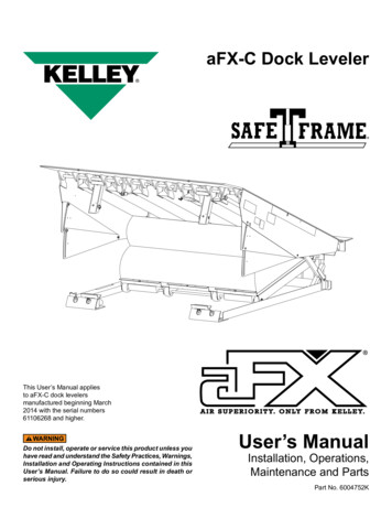
RAMP LIP GRADESFig. 1Lip gradeRamp gradeVEHICLE BED POSITION (in)ABOVEDOCKBELOWDOCK5.04.54.0EOD GRADE 5.0-3.5-4.6-5.7-13.5-14.6-15.7Verify with the manufacturers of all equipment to be usedon your specific edge-of-dock leveler, to ensure thatoperating equipment at all specified grades are withinsafe operation. Do not operate any equipment that willnot safely operate at any of the above stated grades ateither ramp or lip. Failure to follow this warning couldresult in death or serious injury.March 20176016089B — Mechanical Edge-of-Dock Levelers Entrematic Group AB 20175
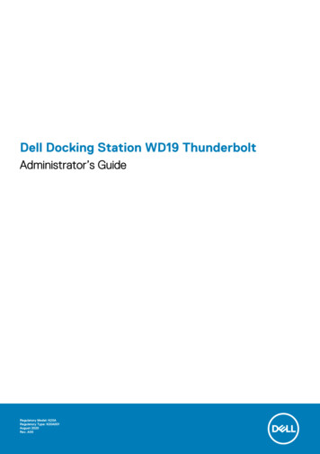
INSTALLATIONDOCK MOUNTING STEEL REQUIREMENTSBefore installing the dock leveler, read and follow SafetyPractices on page 3. Place barricades around pit on dockfloor and drive while installing, maintaining or repairingdock leveler.All anchor bolts used must be installed in accordancewith the manufacturer’s instructions. Do not installanchor bolts in cracks or expansion joints in concrete.Installation in cracks or expansion joints may causethe anchors to come loose and pull out. All anchor boltlengths must suit local codes and conditions. Typeand depth of concrete will determine type and lengthof anchor bolts required. Use of improperly installedanchor bolts could result in death or serious injury.Fig. 2Curb channelWeldDock(concrete)Dock levelershown forreference only1. The face of the dock must be equipped with a minimum of8” channel with anchor straps on 10" centers. MOUNTINGON CURB ANGLE ALONE IS NOT RECOMMENDED.2. There are four main mounting methods: installationwith curb channel, transition plate, face plate and withtransition plate, and formed angle. Follow the sectionthat addresses your installation and then continue to theGENERAL INSTALLATION section on page 10 of thismanual.Dock levelerbase plateCurb channel(Isometric view)INSTALLATION WITH CURB CHANNEL1. If curb channel is not already present, position it asshown in Fig. 2. Pour concrete.NOTE:Concrete preparation should provide adequate depth andwidth to accommodate the channel with sound concretefoundation. Tie in rebar with anchor straps. Check localbuilding codes for further information.2. Ensure all concrete is thoroughly cured before installationand use of dock leveler.3. Proceed to GENERAL INSTALLATION section on page10 of this manual.6 Entrematic Group AB 20176016089B — Mechanical Edge-of-Dock LevelersMarch 2017
INSTALLATION, continuedINSTALLATION WITH TRANSITION PLATENOTE:A transition plate is required whenever the curb channel is lessthan the 8" recommended by Entrematic, or whenever the edgeof dock is to be mounted above dock level.Fig. 3BeveledtransitionplateWeldDock levelermounting plate1. Lay the transition plate on top of dock.2. If using a beveled transition plate, position transitionplate flush with the front of dock edge and skip to step 6.See Fig. 3.3. If using a kinked transition plate, position transitionplate flush with the front of dock edge and mark thelocation of the back of the transition plate on floor ofdock. See Fig. 4.Dock(concrete)Dock levelershown forreference only4. Slide transition plate forward 2" and mark location of theback of the transition plate on floor of dock.5. Remove transition plate and cut a groove in the concrete1/2" deep between lines marked in steps 3 and 4.Position plate flush with the front of the dock edge.6. Tack weld transition plate to curb angle in at least fourplaces.7. Install 5/8" dia x 5" long (supplied by others) wedge anchorbolts in the transition plate. Torque to manufacturer’sspecification. Tack in place. Remove nuts, cut bolts flushwith top of transition plate and plug weld bolts to plate.See page 12 for wedge anchor installation instructions.Fig. 4KinkedtransitionplateWeldDock levelermounting plateAll anchor bolts must be installed in accordance withthe manufacturer’s instructions. Improper installationcould result in death or serious injury.Do not install anchor bolts in cracks or expansion jointsin concrete. Installation in cracks or expansion jointsmay cause the anchors to come loose and pull out.Use of improperly installed anchor bolts could result indeath or serious injury.Dock(concrete)Dock levelershown forreference onlyNOTE:All anchor bolt lengths must meet local codes and conditions.Type and depth of concrete will determine type and length ofanchor bolts required.8. Proceed to GENERAL INSTALLATION section on page10 of this manual.March 20176016089B — Mechanical Edge-of-Dock Levelers Entrematic Group AB 20177
INSTALLATION, continuedINSTALLATION WITH FACE PLATE WITHTRANSITION PLATEFor installations above dock floor height (up to 3" max)the transition plates listed in Fig. 5 must be used.Fig. 5Plate LengthApplicationPart Number12"(1-1/2" or less above dock)600762118"(1-1/2" to 2-1/4" above dock)600762324"(1-1/2" to 3" above dock)60076251. Position the face plate at desired height above docklevel (0" minimum to 3" maximum). See Fig. 6.2. Continuously weld the face plate to the mounting surfacewith a 1/4" fillet in accordance with AWS Standards. SeeFig. 6.3. Position transition plate flush with the top edge of theface plate. Mark along back edge of transition plate ontop of dock.4. Move the transition plate 2" forward. Mark another linealong the back edge of transition plate on top of dock.Fig. 6Transition plate(See Fig. 5)Schedule40 pipeWeldDock levelerbase plate5. Remove the transition plate and cut a groove in theconcrete 2" wide x 1/2" deep between the lines markedin steps 3 and 4.6. While supporting the transition plate against the top backedge of the face plate. Measure and place full lengthstructural angle (supplied by others) as shown. Weld toback of face plate.Curbangle7. Locate and weld full length a (supplied by others) tobottom of transition plate as required.Dock(concrete)8. Install 5/8" x 5" anchor bolts (supplied by others) with thetransition plate. Torque to manufacturer’s specification.Remove nuts, cut bolts flush with top of transition plateand plug weld bolts to plate. See page 12 for wedgeanchor installation instructions.9. Continuously weld the transition plate to the face platewith a 1/4" fillet in accordance with AWS Standards. SeeFig. 6.Weld a full width piece ofstructural angle here(weld to leveler first) toalign leveler andprovide a purchasefor edge of transition plate.Face plateDock levelershown forreference only10. Proceed to GENERAL INSTALLATION section on page10 of this manual.8 Entrematic Group AB 20176016089B — Mechanical Edge-of-Dock LevelersMarch 2017
INSTALLATION, continuedINSTALLATION WITH FORMED ANGLE1. Lay formed angle on top of dock.2. If there is no curb angle, some concrete onedge-of-dock may need to be removed to allow angle tolie flush against wall. See Fig. 7.Fig. 7Formed angleRemove concrete asrequired (2" max ineach direction).Fill in with concreteas required.Dock levelerbase plate3. If there is curb angle present, the lower portion of formedangle will need to be spaced out to allow angle to lieflush against wall. See Fig. 8.4. Position formed angle in desired position on dock edgeand mark location of back of angle on floor of dock.5. Slide formed angle forward 2" and mark location of backof angle on floor of dock.Dock(concrete)Dock levelershown forreference only6. Remove angle and cut a 2" wide x 1/2" deep groove inthe concrete between two lines marked in steps 4 and 5.7. Place formed angle on dock, making sure back edge ofleg on top of dock is recessed in groove and both legsare tight against top and face of dock. Increase depth orwidth of groove as required.8. Install 5/8" x 5" anchor bolts (supplied by others) ontop and front faces on 10" centers. All anchor positionsmust be used. Torque to manufacturer’s specification.Remove nuts from bolts on top of dock. Cut bolts flushwith top of angle and plug weld bolts to formed angle.Weld nuts to bolts and angle on face of dock. See page12 for wedge anchor installation instructions.Fig. 8Formed angleCurbangleWeldDock levelerbase plate9. Position the dock leveler base plate 1/4" below top offormed angle.10. Proceed to GENERAL INSTALLATION section on page10 of this manual.Dock(concrete)Shim as requiredfor rigid supportMarch 20176016089B — Mechanical Edge-of-Dock Levelers Entrematic Group AB 20179
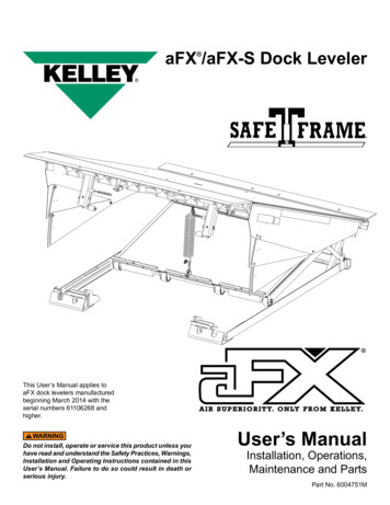
INSTALLATION, continuedGENERAL INSTALLATIONRead and follow Safety Practices on page 3. Failure tofollow these safety practices could result in death orserious injury.Installation should not be attempted by persons notfamiliar with equipment and techniques required forproper installation. Improper installation could result indeath or serious injury.1. Using a 1,000 lbs. minimum capacity load centeringeye bolt, secure the lip plate using the lifting hole. at thecenter of the width. See Fig. 9.Inadequate lifting equipment or practices can cause aload to fall unexpectedly. Make sure the lifting chain orother lifting devices are in good condition and have arated capacity of at least 1000 lbs. for the lifting angleused. Never allow anyone to stand on or near the dockleveler when it is lifted or placed onto the dock. Standclear of the dock leveler when it is being placed ontothe dock. Failure to follow this warning can allow thedock leveler to fall, tip, or swing into people, resulting indeath or serious injury.Do not allow lip and ramp to fall free. Allowing the dockleveler to fall free could result in the dock leveler comingfree from the dock or damaging linkage, resulting indeath or serious injury. Do not allow lip to extend outaway from the dock before all welding and anchorinstallation is complete. Operating the dock levelerbefore all installation is complete could result in deathor serious injury.4. With use of the lifting chain, carefully lower lip to its storedposition as shown in Fig. 19. Remove lifting chain.Use care when welding. Do not allow weld or weldsplatter on the hinge tubes. Weld on the hinge tubesmay interfere with normal operation of the dock leveler.5. Ensure the base plate is plumb and flush with the dockwall. Tack weld behind each base plate tube. Weld outas shown in Fig. 11 using minimum 1/4" welds. Weldtypical on base plate tubes.Fig. 9Lifting hookLipRampThe maintenance strut must always be installed intothe maintenance strut cup mounted to the base platewhenever the lip plate is in the up position and the lipplate is not supported by the lifting chain. Failure tofollow this warning can allow the dock leveler to fallresulting in death or serious injury.2. Position dock leveler mounting plate centered on face ofdock and 1/4" below top of curb channel, transition plateor formed angle plate. See Fig. 9.The dock leveler must be plumb to dock face to operateproperly. Use shims or remove concrete as necessaryto make the mounting plate plumb.MountingclipAnchorholes(as required)Load centeringeye boltBaseplate1/43. Weld two 1/4" x 2" welds at the upper outside edges ofthe mounting plate and plug weld the two outer holesin the mounting plate (if curb channel is not used,install two 5/8" x 5" anchors. Torque to manufacturer’sspecification).10 Entrematic Group AB 20176016089B — Mechanical Edge-of-Dock LevelersMarch 2017
INSTALLATION, continuedDo not allow lip and ramp to fall free. Allowing the dockleveler to fall free could result in the dock leveler comingfree from the dock or damaging linkage, resulting indeath or serious injury.Do not allow lip to extend out away from the dockbefore all welding and anchor installation is complete.Operating the dock leveler before all installation iscomplete could result in death or serious injury.Fig. 101/41/4As required1/4As requiredFailure to keep lip extender link disengaged whilelowering dock leveler could result in damage to the link.6. Support dock leveler by inserting hand lever into cup.7. With the hand lever, raise the ramp to the upright positionand lower back to the rest position, checking for bindingof the ramp and mounting plate hinge.8. Plug weld remaining anchor holes in mounting plate(if curb channel is not used, install remaining 5/8" x 5"anchors. Torque to manufacturer’s specification). Seepage 12 for wedge anchor installation instructions.All anchor bolts must be installed in accordance withthe manufacturer's instructions. Improper installationcould result in death or serious injury.9. Position the bumper blocks aligned with the top edgeof the dock (or top edge of transition plate if used) withthe flange facing away from the leveler but the flat sidealong the edge of the base plate. Tack in place.Do not install anchor bolts in cracks or expansion jointsin concrete. Installation in cracks or expansion jointsmay cause the anchors to come loose and pull out.Use of improperly installed anchor bolts could result indeath or serious injury.10. Check for square alignment. Correct any misalignment.11. Weld bumper with a continuous 1/4" minimum beadacross the top and adjacent to the leveler in accordancewith AWS standards. See Fig. 10.12. Anchor bumpers with 5/8" x 5" deep anchors in holesprovided. Torque to manufacturer’s specification. Seepage 12 for wedge anchor installation instructions.13. Add 3" x 3" x 1/4" angle clips and anchors as required tostabilize bumper. See Fig. 10.March 2017All anchor bolt lengths must suit local codes andconditions. Type and depth of concrete will determinetype and length of anchor bolts required.14. Clean away all debris and paint all welded joints.15. Mount warning and operation placards on wall next todock leveler.16. Test operation of dock leveler. Adjust if necessary. SeePage 19.6016089B — Mechanical Edge-of-Dock Levelers Entrematic Group AB 201711
INSTALLATION, continuedFig. 118"4"4"4"4"8"Use anchor bolts when installed on curb anglePlug weld anchor holes when mounting on embed channels (six places)WEDGE ANCHOR INSTALLATION(USE WITH CURB ANGLE AND TRANSITIONPLATE ONLY)Fig. 12When anchors are used with curb angle for mounting, atransition plate must also be used. See page 7.Do not install the anchor bolts into aged or unsoundconcrete.Use 5/8" x 5" long wedge anchors on smooth 4,000 PSIconcrete walls only. For aggregate, cinder block or tiltwalls - consult factory.Oversized holes in the base material will make it difficultto set the anchor and will reduce the anchor’s loadcapacity.Do not use an impact wrench to set or tighten the wedgeanchors.Drill a hole in the concrete using a carbide drill bit the samediameter as the nominal diameter of the anchor to beinstalled. Drill the hole to the specified embedment depthand blow it clean using compressed air. Alternatively, drill thehole deep enough to accommodate embedment depth anddust from drilling. Assemble the anchor with nut and washerso the top of the nut is flush with the top of the anchor. Placethe anchor in the fixture and drive into the hole until washerand nut are tight against fixture. Torque to manufacturer’sspecification. See Fig. 12.12 Entrematic Group AB 20176016089B — Mechanical Edge-of-Dock LevelersMarch 2017
OPERATION INSTRUCTIONSINTRODUCTIONBefore operating the dock leveler, read and follow SafetyPractices on page 3.Use by untrained people could result in death or seriousinjury. Read and follow complete Operation Instructions.DO NOT USE THE DOCK LEVELER IF IT LOOKSBROKEN OR DOES NOT SEEM TO WORK RIGHT. Tellyour supervisor it needs repair.Always be certain that the truck wheels are chocked orthat the truck is locked in place by a truck restrainingdevice and the brakes are set before loading or unloading.Trucks pulling away from the dock unexpectedly couldresult in death or serious injury.Keep both hands firmly on the hand lever while raisingor lowering the dock leveler. Keep other body partsclear of hand lever travel path while raising or loweringthe dock leveler. Do not use legs or feet to move or holdhand lever. Failure to follow these and other providedwarnings could result in death or serious injury.The Edge-of-Dock dock leveler is designed to span andcompensate for space and height differences between aloading dock and freight carrier to allow safe, efficient freighttransfers.The mechanical EOD leveler is spring counterbalanced.A hand lever is used to position the ramp and lip onto thevehicle bed, and to return the dock leveler to the storedposition.Pulling the hand lever back moves the ramp to the full raisedposition. Moving the lever forward extends the dock levelerlip onto the vehicle.After loading, pulling the hand lever back moves the lip offthe vehicle. The hand lever is then moved forward to placethe dock leveler back into stored position.When not in use, the hand lever is to be stored on the wallin its holder.Do not operate the dock leveler if operation causesundue physical strain or if physical impairments couldlead to undue strain in back, muscles, limbs or joints.Visually check that the lip is supported by the vehiclebed before driving or walking on the ramp.Always return the dock leveler to dock level (stored)position before allowing the vehicle to leave the dock.Read and follow all of the operating instructions for theMechanical Edge-of-Dock shown on pages 14 through15.Do not leave the dock leveler unattended in the uprightposition. Always store the dock leveler with the rampplate down, level with the dock floor. See Fig. 13.Never travel on bumper blocks or over the edges of theleveler.To avoid damage to load and dock leveler, do notactivate unit if loads will be in the way of extendedlip. If lip touches loads before resting on carrier floor,move vehicle to allow unit to return to stored position.Remove end load without placing lip on carrier floor. Donot use power equipment to force lip into vehicle or lipor linkage will be damaged.March 20176016089B — Mechanical Edge-of-Dock Levelers Entrematic Group AB 201713
OPERATION INSTRUCTIONS, continued1. Wait until a vehicle is in position against the dockbumpers.Fig. 132. Tell vehicle driver “Your vehicle must stay at the dock.”3. Chock or hitch vehicle.4. If necessary, remove end loads with the ramp in thedock level (stored) position. See Fig. 13. Do not drive onramp without lip supported by vehicle bed.5. To extend the dock leveler lip into the vehicle:5.1 Locate the hand lever and position it into the rampcup, located on the right side of ramp. See Fig. 14.Fig. 14Keep both hands firmly on the hand lever while raisingor lowering the dock leveler. Keep other body partsclear of hand lever travel path while raising or loweringthe dock leveler. Do not use legs or feet to move or holdhand lever.5.2 Pull back on the hand lever until the assembly isfully raised. See Fig. 15. The lip extender link willengage.5.3 Raise hand lever. Lip will extend automatically asthe ramp is lowered onto the truck bed. See Fig.16.5.4 Once the dock leveler is resting securely on thevehicle bed, remove the hand lever. See Fig. 17.Fig. 15Lip extenderlinkDo not operate the dock leveler when anyone is on or infront of it.Stay clear of the dock leveler when it is moving.Do not walk or drive on the dock leveler or lip until it isfully extended and supported by the vehicle bed.Fig. 16Never use a fork truck or other material handlingequipment to lower the ramp and lip sections.Never travel on bumper blocks or over the edges of theleveler.6. Proceed with loading or unloading.14 Entrematic Group AB 20176016089B — Mechanical Edge-of-Dock LevelersMarch 2017
OPERATION INSTRUCTIONS, continued7. Return the dock leveler to the stored position when entryto the vehicle is no longer required.Fig. 177.1 Locate the hand lever and position it into the rampcup located on the right side of the ramp. See Fig.14.Keep both hands firmly on the hand lever while raisingor lowering the dock leveler. Keep other body partsclear of hand lever travel path while raising or loweringthe dock leveler. Do not use legs or feet to move or holdhand lever.Fig. 187.2 Pull back on hand lever until the lip clears the vehiclebed. See Fig. 18.7.3 Raise the hand lever and allow the ramp and lip tolower to their stored position. See Fig. 19.7.4 Return hand lever back into its storage location.8. Unchock or release vehicle.If vehicle leaves with lip resting on vehicle bed, lip willdrop suddenly. Before vehicle leaves, store lip andensure no equipment, material or people are on thedock leveler. Failure to do so could result in death orserious injury from people, equipment or cargo fallingfrom unsupported dock leveler.Fig. 199. Tell vehicle driver, “Your vehicle may now leave thedock.”March 20176016089B — Mechanical Edge-of-Dock Levelers Entrematic Group AB 201715
PLANNED MAINTENANCESTAND CLEAR! The dock leveler moves toward you.Always be certain the ramp is in the raised position,SECURED WITH THE MAINTENANCE STRUT beforedoing any lubrication or repair under the dock leveler.Failure to do so could result in death or serious injury.Do not use hands or feet to hold lip extender linkdisengaged. Use of hands or feet could cause a pinchpoint resulting in death or serious injury.Always return the dock leveler to stored position afterservice. Failure to do so could result in death or seriousinjury.1. With the leveler in the maintenance position, inspect allmoving parts for wear or damage. Repair or replace, asnecessary.Before servicing the dock leveler, read and follow SafetyPractices on page 3.2. Both extension springs should be checked for the sameamount of tension for balanced operation. Check theamount of bolt exposed beyond the spring face - if theamount is the same the springs are adjusted evenly adjust as required. Check for deformation to washers.TO INSTALL THE MAINTENANCESTRUT (2 PEOPLE REQUIRED)1. Using the hand lever, position the dock leveler in the fullback position. See F
Use of dock leveler is restricted to trained operators. Follow procedures on placards posted near dock leveler. Call 972-466-0707 or 800-525-2010 for replacement placards, warning labels or owner's manual. Never exceed the rated capacity of the dock leveler. Do not operate the dock leveler with equipment, material or people on the ramp or lip.