Transcription
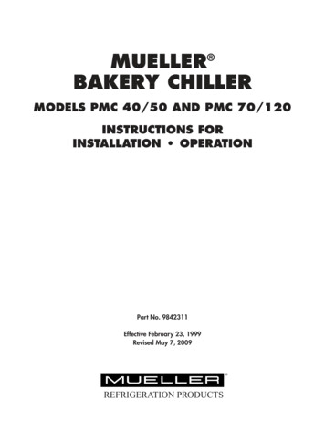
MUELLERBAKERY CHILLER MODELS PMC 40/50 AND PMC 70/120INSTRUCTIONS FORINSTALLATION OPERATIONPart No. 9842311Effective February 23, 1999Revised May 7, 2009 REFRIGERATION PRODUCTS
BAKERY CHILLER MODELS PMC 40/50 AND PMC 70/120INSTRUCTIONS FOR INSTALLATION AND OPERATIONTable of ContentsSection 1.0 - Bakery Chiller Introduction1.11.21.31.41.51.61.7Introduction . . . . . . . . . . . . . . . . . . . . . . .Mueller Bakery Chiller Evaporator AssemblyDimensions and Weight . . . . . . . . . . . . . . .Description of the Equipment . . . . . . . . . .Refrigeration Components . . . . . . . . . . . . .Liquid Solution Flow Components . . . . . . .Electrical Components . . . . . . . . . . . . . . . .1.1.1.1.2.2.2.3.3.3.3.4Section 2.0 - Installation2.12.22.32.42.5Inspection . . . . . . . . . . . . . .Safety . . . . . . . . . . . . . . . . .Location . . . . . . . . . . . . . . .Chilled Water Piping . . . . . .Refrigeration Unit Installation.Section 3.0 - First Time Start-Up and Cleaning the System3.13.2First Time Start-Up and Cleaning Procedure . . . . . . . . . . . . . . . . . . . . . . . . . . . . . . . . . . . . . . . . . . . . .5Filling the System . . . . . . . . . . . . . . . . . . . . . . . . . . . . . . . . . . . . . . . . . . . . . . . . . . . . . . . . . . . . . . . .5Section 4.0 - Programming and Troubleshooting4.14.24.34.44.54.6Power On Sequence of Operation . . . . . . . . . .Error Messages . . . . . . . . . . . . . . . . . . . . . . . .Locking and Unlocking Temperature ControllerProgramming Temperature Setpoints . . . . . . . .Changing Calibration Offset . . . . . . . . . . . . . . .Fahrenheit Celsius Conversion . . . . . . . . . . . . .6.6.7.7.7.8Section 5.0 - Diagrams5.15.25.3Wiring Diagram, Part No. 9842313 . . . . . . . . . . . . . . . . . . . . . . . . . . . . . . . . . . . . . . . . . . . . . . . . . . . .9Bakery Chiller PMC Model 70/120 Flow Diagram . . . . . . . . . . . . . . . . . . . . . . . . . . . . . . . . . . . . . . . .10Bakery Chiller PMC Model 40/50 Flow Diagram . . . . . . . . . . . . . . . . . . . . . . . . . . . . . . . . . . . . . . . . .10
Table of Contents - ContinuedSection 6.0 - Parts Illustrations6.16.26.36.46.56.6Control Box . . . . . . . . . . . . . . . . . . . . . . . . . .Control Box Parts List . . . . . . . . . . . . . . . . . . .Chiller Assembly Model PMC 40/50 . . . . . . . .Chiller Assembly Parts List Model PMC 40/50 .Chiller Assembly Model PMC 70/120 . . . . . . . .Chiller Assembly Parts List Model PMC 70/120.11.11.12.13.14.15Specifications/Electrical Data for Model PMC 40/50 with 2 HP Unit . .Specifications/Electrical Data for Model PMC 70/120 with 3.5 HP UnitRefrigeration Cycle Diagram . . . . . . . . . . . . . . . . . . . . . . . . . . . . . . .EPA Refrigerant Regulations . . . . . . . . . . . . . . . . . . . . . . . . . . . . . . .Thermal Expansion Valve (TEV) Superheat Adjustment . . . . . . . . . . .Thermal Expansion Valve Superheat Adjustment Diagram . . . . . . . . .16.16.17.17.17.18Section 7.0 - Refrigeration Units7.17.27.37.47.57.6Section 8.0 - Warranty . . . . . . . . . . . . . . . . . . . . . . . . . . . . . . . . . . . . . . . . . . . . . . . . . . . . . . . . . . . . . . . . 19Section 9.0 - Installation and Service Notes . . . . . . . . . . . . . . . . . . . . . . . . . . . . . . . . . . . . . . . . . . . . . . 20
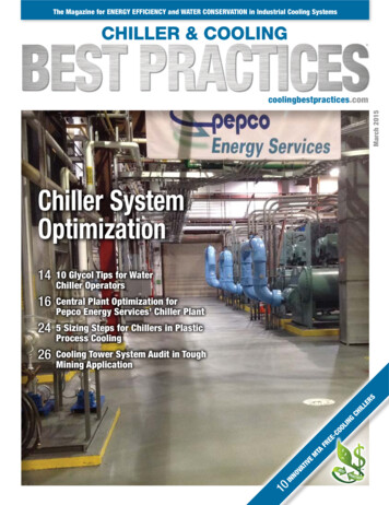
SECTION 1.0 - INTRODUCTION1.1IntroductionThe Mueller bakery chiller is designed to provide chilled water at a preset temperature for batchapplications. This manual provides the basic information necessary to install, start-up, and operate thisMueller bakery chiller. The information supplied in this manual must be followed to prevent damage tothe equipment.1.2Mueller Bakery Chiller Evaporator AssemblySuction LineLiquid LineSMake-UpWater InLS1SCondensing UnitBakery ChillerField InstalledProcess Flow SwitchBakery MixerFS1TE1ProcessValvePump1.3Dimensions and WeightPMC 40/50PMC 70/120Length32"42"Width24"34"Height72"84"310 lbs.705 lbs.Approx. Shipping WeightBakery Chiller Models PMC 40/50 and PMC 70/120Installation and Operation Instructions, Part No. 98423111Effective February 23, 1999Revised May 7, 2009
1.4Description of the EquipmentThe Mueller bakery chiller evaporator assembly is available in two sizes and two model variations tomeet installation and application needs.A. Sizes1.PMC 40/50: Nominal 50-gallon storage capacity to be used with a 2 hp condensing unit.2.PMC 70/120: Nominal 120-gallon storage capacity to be used with a 3.5 hp condensing unit.B. Model Variations1.RC: Evaporator assembly and remote condensing unit.2.RS: Evaporator assembly and solenoid valve for a rack system.Example: PMC 40/50 RC1.5Refrigeration ComponentsThe refrigeration components of the evaporator assembly include a thermal expansion valve forrefrigerant control, a stainless steel evaporator that is outside of a baked, glass-lined water tank, andinner-connect refrigerant piping. Single-point refrigeration piping connections are provided for ease ofinstallation that is described is Section 2.5.1.6Liquid Solution Flow ComponentsThe liquid solution flow components include a baked, glass-lined, and insulated water storage tank,water solenoid valve to control make-up water and recirculation, circulation pump, and inner-connectpiping. Single point 3/4" MPT connections are provided for water inlet and chilled water outlet. Thissystem is designed to maintain the water level in the storage tank after each batch of chilled water isdrawn. Make-up water will not enter the storage tank during the batch draw which eliminatestemperature blending of warmer make-up water and chilled water.1.7Electrical ComponentsAll wiring must be performed in compliance with the National Electric Code and local codes andregulations.The control box contains fuses for system protection. Fuse failure requires troubleshooting to determinethe cause of failure and replacement with the same fuses as described in Section 5.0.The electronic temperature control can be set for temperature control of chilled water and temperaturedisplay in Fahrenheit or Celsius. Programming is described in Section 4.0.Bakery Chiller Models PMC 40/50 and PMC 70/120Installation and Operation Instructions, Part No. 98423112Effective February 23, 1999Revised May 7, 2009
SECTION 2.0 - INSTALLATION2.1InspectionBecause it is possible for equipment to be damaged during shipment, we recommend that you make athorough inspection of all equipment before it is unloaded from the freight truck. Carefully inspectequipment for hidden damage. It may be difficult to collect for damage if it is not found prior tounloading. It is very important to note any damage on the bill of lading and have the driver sign it.2.2SafetyInstallation and service should be performed by an authorized service technician who has the propertraining to install and service refrigeration equipment. Effective November 1994, the service technicianmust be certified in refrigerant usage by an EPA-approved testing organization prior to installing orservicing any refrigeration equipment.All electrical connections must be performed by a qualified electrician in accordance with local andNEC regulations.2.3LocationWhen choosing a location for the Mueller bakery chiller, consider these items:2.4 Environment: An indoor location will be necessary where the chiller section is protected fromfreezing temperature. Serviceability: The chiller should be located with the circulating pump and the control panelaccessible for service. Keep in mind the chiller will require field connections to the main electricalsupply and water supply line. The chiller should be located close to a drain for service andcleaning. Refrigeration Unit: The refrigeration unit (for PC and RC models) must be located where they areprotected from the environment and have adequate air-flow for the condenser. Be especiallycautious of conditions that would allow dust or oil to enter the condenser. Efficiency: Locate the chiller as close as possible to point of use for chilled water.Chilled Water PipingThe bakery chiller supply water should be connected to the 3/4" inlet water solenoid valve located atthe top of the water tank (refer to Figure 3, “Flow Diagram”). The supply water line should be takenfrom a source that provides adequate water flow and a minimum of 3/4" in size. It is recommended thata full flow shut-off valve and union be installed just prior to the solenoid valve for service.The chilled water supply should be connected to the 3/4" chilled water outlet located near thecirculation pump. Keep this line as short as possible to allow for chilled water of desired temperatureto be provided to point(s) of use. This line should be insulated to reduce external heat gain to thechilled water.Check all piping for leaks and repair if required. Clean and rinse lines and water storage tank prior tousage.Bakery Chiller Models PMC 40/50 and PMC 70/120Installation and Operation Instructions, Part No. 98423113Effective February 23, 1999Revised May 7, 2009
2.5Refrigeration Unit InstallationAll refrigerant piping should be in accordance to acceptable refrigeration practices. Distance betweenrefrigeration unit and bakery chiller assembly should be as close as possible. Long distance piping andrisers may require attention to reduce restriction of refrigerant flow and to provide adequate oil return.The liquid line should be 3/8" OD copper pipe and the suction line 7/8" OD copper pipe. A liquid linedrier of adequate size should be installed on all PMC 40/50 RS and RC models. A liquid line drier isprovided on 3.5 hp. units for PMC 70/120 RS and RC models. A liquid line sight glass should beinstalled just prior to the thermal expansion valve (TEV) on the bakery chiller evaporator assembly.Attach the thermal expansion valve sensing bulb to the suction line and insulate after refrigerant linesare installed as shown in Section 7.3 and Figure 7.Evacuation to 500 microns prior to charging with refrigerant is required. The system must hold 1,000microns in a standing vacuum test, ensuring that it is leak free.Refrigerant charging should be through the suction service valve in vapor form only. Charge with anadequate amount of refrigerant prior to starting the compressor and make sure that water storage tankis filled with water. Refer to Section 3.0 for start-up procedures.The initial refrigerant charge for PMC 40/50 model with a 2 hp unit is 6 lbs R-22 or 5 lbs. R-507refrigerant. The initial refrigerant charge for PMC 70/120 models with a 3.5 hp unit is 13 lbs R-22 or 12lbs. R-507 refrigerant.Bakery Chiller Models PMC 40/50 and PMC 70/120Installation and Operation Instructions, Part No. 98423114Effective February 23, 1999Revised May 7, 2009
SECTION 3.0 - FIRST TIME START-UP AND CLEANING THE SYSTEM3.13.2First Time Start-Up1.Make sure that the water piping is complete as described in Sections 2.4 and 5.0, Figure 3, andrefrigeration piping is complete as described in Sections 2.5 and 7.0. Make sure that the wiring iscomplete as described in Section 5.0.2.The first step to start-up will be to open the supply water shut-off valve(s). Open the drain valvelocated at the outlet of the water storage tank. A toggle switch that disables the circulation pump islocated inside the control box in the upper right hand corner of the back panel. The up positionwill allow the pump to run and the down position will disable the pump. Any time the tank isempty, or on initial start-up, the operator must disable the circulation pump. This willallow the fill solenoid to fill the tank and prevent the pump from running dry. Turn thetoggle switch to the down position. Turn the power on to the control panel. Make sure the poweris off to the refrigeration unit during this part of start-up. Push the green push button switch on thefront of the control panel to energize the system. This will allow water to flow to the storage tank.Allow water to flow until clean and clear water is flowing out of the drain. Close the drain valveand allow the storage tank to fill.3.Turn the toggle switch to the up position and allow the circulation pump to operate for 2 minutesand turn the push button switch off. Open the drain valve again and drain the water from thestorage tank. If the water is not clean repeat the cleaning procedure.Filling the System1.Close the drain valve, turn the toggle switch to the down position, and turn the push button switchon to fill the system with water again. Open the chilled water valve and allow water to flow untilclean. Close the chilled water valve and allow the storage tank to refill with make-up water. Turnthe toggle switch to the up position to operate the circulation pump.2.Complete the initial refrigeration unit charging procedure. Final refrigerant charging is to becompleted in conjunction with the thermal expansion valve (TEV) superheat adjustment asdescribed in Section 7.0.Bakery Chiller Models PMC 40/50 and PMC 70/120Installation and Operation Instructions, Part No. 98423115Effective February 23, 1999Revised May 7, 2009
SECTION 4.0 - PROGRAMMING AND TROUBLESHOOTING4.1Power On Sequence of OperationA. When the push button is in the OFF (out) position:1.Power is supplied to the temperature controller and a temperature is displayed. Setpoints maybe changed any time power is supplied to the temperature controller. The temperaturedisplayed may not be a true reading of tank temperature if the circulation pump is notrunning.2.All other functions of the bakery chiller are disabled.B. When the push button is in the ON (recessed) position:4.21.Power is supplied to the temperature controller and a temperature is displayed. Setpoints maybe changed any time power is supplied to the temperature controller. The temperaturedisplayed may not be a true reading of tank temperature if the circulation pump is notrunning.2.The system light at the center of the on/off button is on.3.The fill solenoid will allow the tank to fill until the level switch stops the fill near the top of thestorage tank.4.The circulation pump is on. Any time the tank is empty, or on initial start up, theoperator must disable the circulation pump. This will allow the fill solenoid to fill thetank and prevent the pump from running dry. Refer to Section 3.1, “First Time Start-up”for detailed information.5.Water will flow through the chiller recirculation loop piping and solenoid to the top of thetank.6.The condensing unit will operate if the water temperature is above the setpoint.7.When a batch is drawn, the flow through the process piping increases and will open theprocess flow switch contacts, disabling the fill solenoid and condensing unit, and closing therecirculation solenoid.8.When the batch draw is complete, the process flow switch contacts close and the fill solenoidwill refill the storage tank. When the storage tank is full, the temperature controller again hascontrol of the condensing unit.Error MessagesA display reading of “uuuu” is a designation of a disconnected or broken temperature sensor wire.Should this occur, service is required to correct the problem.Bakery Chiller Models PMC 40/50 and PMC 70/120Installation and Operation Instructions, Part No. 98423116Effective February 23, 1999Revised May 7, 2009
4.3Locking and Unlocking the Temperature Controller1.Press and hold the “SEL” key for 5 seconds until “AL1” is displayed. Press the “ ” down key onceto display “LoC.”2.Press the “SEL” key once again to display the locking code (“0” for unlocked and “4” for locked).3.Press the “ ” up key or the “ ” down key until either “0” for unlocked or “4” for locked isdisplayed. (NOTE: You can enter any number between “0” and “5” but only “0” and “4” are active.)4.Press the “SEL” key to save the change made. Controller will once again display “LoC.”5.Press and hold the “SEL” key for 5 seconds until the setpoint value is displayed, indicted by a small“SV” illuminating in the upper left-hand corner of the controller.6.Press the “SEL” key to display the current tank temperature.NOTE: If the “SEL” key is not pressed within approximately 25 seconds the controller will time out andreturn to the current temperature, storing the new setpoint or any changes made.4.4Changing the Setpoint on the Temperature Controller1.Unlock the controller as in Section 4.3.2.Press the “SEL” once to display the setpoint. This is indicted by a small “SV” illuminating in theupper left-hand corner of the controller.3.Press the “ ” up key or the “ ” down key until the desired setpoint is displayed.4.Press the “SEL” key to save the change made and to display the current tank temperature.NOTE: If the “SEL” key is not pressed within approximately 25 seconds the controller will time out andreturn to the current temperature, storing the new setpoint or any changes made.4.5Changing the Calibration Offset on the Temperature Controller1.Unlock the controller as in Section 4.3.2.Press and hold the “SEL” key for 7 seconds until “P-F” is displayed.3.Press the “ ” down key once to display “PUOF.”4.Press the “SEL” key once to display the calibration offset.5.Press the “ ” up key or the “ ” down key to adjust the calibration offset to the amount of offsetrequired to match the actual water temperature. (The calibration offset may be used to set theactual temperature display should it not be the same as the water temperature in the storage tank.)6.Press the “SEL” key to save the change made. Controller will once again display “PUOF.”7.Press and hold the “SEL” key for 5 seconds until the setpoint value is displayed, indicted by a small“SV” illuminating in the upper left hand corner of the controller.Bakery Chiller Models PMC 40/50 and PMC 70/120Installation and Operation Instructions, Part No. 98423117Effective February 23, 1999Revised May 7, 2009
4.5Changing the Calibration Offset on the Temperature Controller (Continued)8. Press the “SEL” key to display the current tank temperature.NOTE: If the “SEL” key is not pressed within approximately 25 seconds the controller will time out andreturn to the current temperature, storing the new setpoint or any changes made.4.6To Change the Units of Measure on the Temperature Controller:NOTE: Once the display has been changed to the desired units of measure ( F or C), the temperaturesetpoint must also be changed to match the units (i.e., 36 F or 2.2 C). Call Paul Mueller Company forassistance.1.Unlock the controller as in Section 4.3.2.Press and hold the “SEL” key for 7 seconds until “P-F” is displayed.3.Press the “SEL” once to display the current temperature unit of measure (“F” for Fahrenheit and “C”for Celsius).4.Press the “ ” up key or the “ ” down key until either “F” for Fahrenheit or “C” for Celsius isdisplayed.5.Press the “SEL” key to save the change made. Controller will once again display “P-F.”6.Press and hold the “SEL” key for 5 seconds until the setpoint value is displayed, indicted by a small“SV” illuminating in the upper left hand corner of the controller.7.Press the “SEL” key to display the current tank temperature.NOTE: If the “SEL” key is not pressed within approximately 25 seconds the controller will time out andreturn to the current temperature, storing the new setpoint or any changes made.Bakery Chiller Models PMC 40/50 and PMC 70/120Installation and Operation Instructions, Part No. 98423118Effective February 23, 1999Revised May 7, 2009
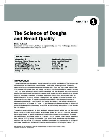
SECTION 5.0 - DIAGRAMS5.1Wiring Diagram, Part No. 9842313A Type T thermocouple is provided for the temperature sensor. It is important that thethermocouple wires are connected to the temperature control properly. The constantan(silver) wire is to be connected to terminal 10 on the temperature control. The copperwire is to be connected to terminal 11 on the temperature control.Bakery Chiller Models PMC 40/50 and PMC 70/120Installation and Operation Instructions, Part No. 98423119Effective February 23, 1999Revised May 7, 2009
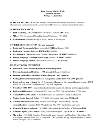
5.2Bakery Chiller PMC Model 70/120 Flow DiagramInlet WaterSolenoidWaterLevelSwitchSSupply Water InletLS1VentSChiller BarrelProcessFlow ion PumpDrainValve5.3Bakery Chiller PMC Model 40/50 Flow DiagramWaterLevelSwitchLS1VentSInlet WaterSolenoidSSupplyWaterInletChiller BarrelProcessFlow ion PumpDrainValveBakery Chiller Models PMC 40/50 and PMC 70/120Installation and Operation Instructions, Part No. 984231110Effective February 23, 1999Revised May 7, 2009
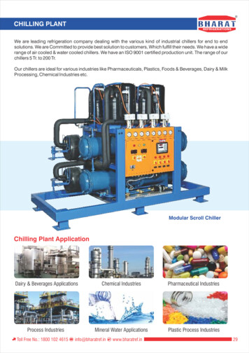
SECTION 6.0 - PARTS ILLUSTRATIONS6.1Control Box 8820261PRODUCTMODEL NUMBERVOLT SPART NUMBERSERIAL NUMBERHERTZ PHASE LRG MTR AMPSFLADISCONNECT MAIN POWER SUPPL Y BEFORE SER VICING.ROMPRE LE CABLE DE DISTRIBUTION AV ANT DE REPARER.000730890BACK PANEL LAYOUTFRONT VIEW6.2Control Box Parts ListITEMNO.NO.REQ’D.PART NO.DESCRIPTION19842292CONTROL BOX ASSEMBLY - BAKERY119844261CONTROLLER, TEMPERATURE219842305SWITCH, PUSH BUTTON, LIGHTED318820718TRANSFORMER, 208-240V, PRM, 24V SEC419842306SWITCH, RELAY, DPDT, 24VAC529820091FUSE BLOCK, 30 AMP, CLASS CC61505793BARRIER, ELEC END FUSE729823754FUSE, CARTRIDGE, 7 AMP828820703FUSE, BLOCK, 30 AMP918806523FUSE, CARTRIDGE, 2 AMP1068805635TERMINAL BLOCK1118805636BARRIER, ELEC END1228805226CLIP, RETAINER1328820240RELAY, SWITCH, DPST, 24VAC1418820165THERMOCOUPLE, SENSOR, TYPE “T”15130853Bakery Chiller Models PMC 40/50 and PMC 70/120Installation and Operation Instructions, Part No. 9842311SWITCH, TOGGLE, DPST11Effective February 23, 1999Revised May 7, 2009
6.3Chiller Assembly Model PMC 40/50DETAIL CDETAIL BTOP VIEWDETAIL AELEVATION VIEWBakery Chiller Models PMC 40/50 and PMC 70/120Installation and Operation Instructions, Part No. 984231112Effective February 23, 1999Revised May 7, 2009
6.4Chiller Assembly Parts List Model PMC 40/50ITEMNO.NO.REQ’D.19842289CHILLER, BAKERY MODEL PMC 40/50119842259WATER PUMP, CIRCULATING, .75HP219842292CONTROL BOX ASSEMBLY319842309SWITCH, FLOW, MAGNETIC429842295VALVE, SOLENOID, .75" NPT519842300VENT, TANK, .75" FPT618802042TUBE, INLET WATER719843059SWITCH, LEVELPART NO.DESCRIPTION81300419.007SF3202023RUBBER, .125" THK10A19842303VALVE, EXPANSION, R-2210B19844289VALVE, EXPANSION, R-507113937551219843187Bakery Chiller Models PMC 40/50 and PMC 70/120Installation and Operation Instructions, Part No. 9842311CLAMP, HOSELEG, ASSEMBLYREGULATOR FLOW .75", 10 GPM13Effective February 23, 1999Revised May 7, 2009
6.5Chiller Assembly Model PMC 70/120DETAIL ADETAIL BDETAIL ETOP VIEWDETAIL FDETAIL DELEVATION VIEWBakery Chiller Models PMC 40/50 and PMC 70/120Installation and Operation Instructions, Part No. 984231114Effective February 23, 1999Revised May 7, 2009
6.6Chiller Assembly Parts List Model PMC 70/120ITEMNO.NO.REQ’D.19842291CHILLER, BAKERY MODEL PMC 70/120119842259PUMP, WATER, CIRCULATING, .75HP219842292CONTROL BOX ASSEMBLY319842309SWITCH, FLOW, MAGNETIC429842295VALVE, SOLENOID, .75" NPT519842315VENT, TANK, 1.25" FPT618802042TUBE, INLET WATER719843059SWITCH, LEVELPART NO.DESCRIPTION81300419.007SF3202023RUBBER, .125" THK10A18802355VALVE, EXPANSION, R-2210B19844291VALVE, EXPANSION, TOR FLOW .75", 10 GPMBakery Chiller Models PMC 40/50 and PMC 70/120Installation and Operation Instructions, Part No. 9842311CLAMP, HOSELEG, ASSEMBLY15Effective February 23, 1999Revised May 7, 2009
SECTION 7.0 - REFRIGERATION UNITS7.1Specifications/Electrical Data for PMC 40/50 With 2 HP UnitSPECIFICATIONSPartNumberUnitModelNumberOverall 9842322F3AM-A20124.118.316.93 89844295FJAM-A15024.118.316.93 8SuctionApproximateLineShipping WeightValve(lbs.)/ FL7 8/ FL7 8CompressorModel No./ SWT140CRD1-0201/ SWT140CS10K6EELECTRICAL fication/Electrical Data for PMC 70/120 With 3.5 HP UnitSPECIFICATIONSPartNumberUnitModelNumberOverall SuctionLineValveApproximateShipping Weight(lbs.)CompressorModel No.8822363OESE-A35140.130.431.53 88822362OESE-A35340.130.431.53 8/ SWT7 8/ SWT358ZB26KA-PFV/ SWT7 8/ SWT358ZB26KA-TFSELECTRICAL 0NOTE: The 2.0 hp remote condensing unit is suitable for outdoor operation with the addition of lowambient controls and weather protection. Call the factory for more information.Bakery Chiller Models PMC 40/50 and PMC 70/120Installation and Operation Instructions, Part No. 984231116Effective February 23, 1999Revised May 7, 2009
7.3Refrigeration Cycle DiagramSuction LineAir-Cooled Condensing UnitLiquid LineLiquid LineSight GlassThermostaticExpansionValveSuction LineService ValveLiquid LineService ValveBakery Chiller7.4EPA Refrigerant Regulations*The Mueller bakery chiller system is designed to operate with R-22 (chlorodiflouromethane), a Class IIHCFC refrigerant. R-22 refrigerant is specified by ASHRAE Standard 34 Safety Classification as an “A-1”refrigerant that represents low-flame propagation and low toxicity.EPA regulations require that any technician performing refrigerant installation or service on a highpressure appliance be certified as a Type II Technician in accordance with Section 608 of the Clean AirAct.*As adopted for the United States and Canada. These regulations may change or differ for your locality.It is the responsibility of the technician performing the refrigerant service and/or installation to abide byall regulatory requirements for the installation locality, state, and country.7.5Thermal Expansion Valve (TEV) Superheat AdjustmentTake the following readings with the water storage tank full of water at a temperature below 40 F.1.Take an accurate suction pressure at the evaporator outlet.SERVICE NOTE: The suction pressure must be taken at the evaporator outlet rather than thesuction-service valve due to unknown pressure drop in the refrigerant line between the evaporatorand compressor (refer to Figure 8). The technician should also make certain that the system ischarged with refrigerant as described in Section 2.0.2.Utilizing an accurate electronic thermometer, take the actual suction line temperature near the TEVsensing bulb.Bakery Chiller Models PMC 40/50 and PMC 70/120Installation and Operation Instructions, Part No. 984231117Effective February 23, 1999Revised May 7, 2009
7.57.6Thermal Expansion Valve (TEV) Superheat Adjustment (Continued)3.Utilizing an R-22 or R-507 Pressure Temperature Chart, convert the suction pressure reading fromStep 1 to saturation temperature.4.The superheat value is found by subtracting the saturation temperature determined in Step 3 fromthe actual suction line temperature taken in Step 2.5.If the superheat is not in the range of 8 to 10 F, at conditions as described above, adjust the TEV.6.If the superheat is below 8 F, turn the TEV’S adjustment stem clockwise 1/8 to 1/4 of a turn. Allowthe system to operate for 5 minutes before repeating test.7.If the superheat is above 10 F, turn the TEV’s adjustment stem counterclockwise 1/8 to 1/4 of a turn.Allow the system to operate for 5 minutes before repeating test.8.Any time adjustment is made to the TEV, the refrigerant charge should be checked.9.Check the superheat setting and make final adjustments at a product temperature near setpoint forbest performance.Thermal Expansion Valve Superheat Adjustment DiagramSuction LineAir-Cooled Condensing UnitThermostaticExpansionValveTEVSensing BulbThermometerSuction GaugeLiquid LineSuction LineService ValveLiquid LineSight GlassLiquid LineService ValveBakery ChillerBakery Chiller Models PMC 40/50 and PMC 70/120Installation and Operation Instructions, Part No. 984231118Effective February 23, 1999Revised May 7, 2009
SECTION 8.0 - WARRANTYWA R R A N T YMueller Bakery ChillerOne Year Parts WarrantyThe Paul Mueller Company (hereafter referred to as Company) will repair or (at the Company’s option) replaceany part or portion of a Mueller Bakery Chiller found to be defective in workmanship or material under normaluse, service, and installation procedures, for a period of one (1) year from the date of installation by theoriginal purchaser-user, or eighteen (18) months from the date of shipment from the Company factory,whichever occurs first. This warranty covers replacement of parts or repair of the equipment only. (See GeneralProvisions).Claim Procedures for One Year Parts WarrantyAll defective parts covered by the one year parts warranty, must be returned to the Company with an attachedReturned Goods Tag (Form O-209) and with transportation cost prepaid. Current instructions provided by theRefrigeration Products Department for return procedures must be followed to receive warranty.Five-Year Structural Warranty
The Mueller bakery chiller is designed to provide chilled water at a preset temperature for batch applications. This manual provides the basic information necessary to install, start-up, and operate this Mueller bakery chiller. The information supplied in this manual must be followed to prevent damage to the equipment.