Transcription
CTI ProductsRadioPro IP GatewayInstallation GuideforMotorola MOTOTRBO Radios(XPR 2500, 45xx, 55xx)Document # S2-61903-830For Version 8 Software
RadioPro IP GatewayInstallation and Configuration Guide for MOTOTRBOContact UsSupport, replacement part ordering, and service may be arranged by contacting our Cincinnati office. Parts for servicecan be returned following a request of a Return Material Authorization.CTI Products, Inc.1211 W Sharon RdCincinnati, OH Information in this document is provided with best efforts for completeness and accuracy. However, no guarantee isexpressed or implied, and details may change without notice.Fonts used in this document:Technical termsCross-references within this documentHyperlinks to other documents or web pagesWarningsSoftware menus, menu options, folders, pages, and parametersSoftware parameter values2
RadioPro IP GatewayInstallation and Configuration Guide for MOTOTRBOContents1 OVERVIEW . 41.1 System Planner Document and Template . 41.2 Required Items . 41.2.1 Radio Interface Cable . 41.2.2 Control Station Radio . 41.2.3 Radio Programming Cable . 42. FEATURE AVAILABILITY . 53. CONFIGURATION AND INSTALLATION . 6Step 1a. for Motorola XPR 45XX & 55XX (Voice): . 7Configure Control Station Radio (For Voice) using MOTOTRBO CPS . 7Step 1b. for Motorola XPR 45XX & 55XX (DATA): . 16Configure Control Station Radio (For Data) using MOTOTRBO CPS . 16Step 1c. for Motorola XPR 45XX / 55XX Connect Plus Radios : . 17Configure MOTOTRBO Connect Plus Option Board . 17Step 1d. for Motorola MOTOTRBO Subscriber Radios: . 18Configure Subscriber Radios for ARS, GPS, and TMS . 18Step 1e. for Motorola XPR 2500 Radio: . 22Configure Control Station Radio (For Voice) using MOTOTRBO CPS . 22Step 1f. for Motorola MOTOTRBO Repeater:. 26Configure Motorola Repeaters for Enhanced GPS Option . 26Step 2. for Motorola MOTOTRBO systems: . 27Connect the RadioPro IP Gateway to the Control Station Radio . 27Step 3. Configure RadioPro IP Gateway . 284. APPENDIX . 304.1 Appendix - IP Addressing . 304.2 Appendix – Radio Interface Cables . 31Motorola MOTOTRBO XPR4550/5550 . 31Motorola MOTOTRBO XPR2500 . 325. INDEX . 336. SYSTEM PLANNER TEMPLATE PAGE 1 OF 2 . 34RadioPro IP Gateways. 346. SYSTEM PLANNER TEMPLATE PAGE 2 OF 2 . 35RadioPro Dispatch Clients . 35RadioPro Solo, Talk, and Mobile Clients . 353
RadioPro IP GatewayInstallation and Configuration Guide for MOTOTRBO1 OVERVIEWThis Manual will focus on configuring and using the Motorola MOTOTRBO Radios with the RadioPro System.Please Refer to the RadioPro IP Gateway Installation Guide for general installation information relevant for all radiosystem types.1.1 System Planner Document and TemplateThe RadioPro System Planner for Motorola MOTOTRBO S2-61645 includes examples for various MOTOTRBO radionetwork topologies and should be consulted if the RadioPro Dispatch client is being deployed.Use the System Planner Template on page 34 of this document in the planning phase of a project to record IP addresses,usernames, passwords, serial numbers, and device names.1.2 Required Items1.2.1 Radio Interface CableA radio interface cable must be ordered for each IP Gateway from the following table:Control Station RadioCable Part #Motorola XPR4550/5550S2-61431Motorola XPR2500S2-61916Other cables are available to connect a dedicated data revert radio. Contact CTI for more information.1.2.2 Control Station RadioEach Control Station radio used for voice requires one IP Gateway. The control station radio connected to the IPGateway must at least have the minimum firmware version listed below. Motorola’s CPS (CustomerProgramming Software) software will be needed to configure the control station radio.MinimumVersionProgrammingSoftwareMotorola MOTOTRBO in Conventional, IPSC, Cap , or LCP1.08.0CPSMotorola MOTOTRBO in Connect Plus mode2.2.0CPSMotorola MOTOTRBO Connect Plus Option Board1.3.0CPSControl Station Radio1.2.3 Radio Programming CableEither the Motorola programming cable or the RadioPro Gateway cable may be used with the CPS software toconfigure the Control Station radio.Note: A programming cable connected to the front microphone connector on the Control Station radio mayprevent communications to a RadioPro IP Gateway through the Rear Accessory Connector.WARNING: Remove any other cables from the front microphone connector before attempting to connectand use the RadioPro IP Gateway or a programming PC on the rear accessory connector. The front andrear ports cannot be engaged at the same time.4
RadioPro IP GatewayInstallation and Configuration Guide for MOTOTRBO2. FEATURE AVAILABILITYMotorola MOTOTRBO SystemsDepending on MOTOTRBO System Type, some features may not be available. Use the following table to determine ifa feature discussed in this document is not available.System TypeFeatureAnalogConv.DigitalCap IP SiteConnectLinkedCap ConnectPlusVoiceDispatchTextMessaging - -GPS Mapping- -- -- - ARSPrivate rconnectRec/Mon--5
RadioPro IP GatewayInstallation and Configuration Guide for MOTOTRBO3. CONFIGURATION AND INSTALLATIONUse the steps in the following table to install a RadioPro System. Each step is discussed in detail starting on page 7.Following installation of the IP Gateway in Step 5, at least one Client must be installed from Step 6.Step #DescriptionMotorola MOTOTRBO1aConfigure XPR 45xx / 55xx ControlStation Radio(s) for VoiceS2-61903, page 7IP Gateway Installation GuideConfigure XPR 45xx / 55xx ControlStation Radio(s) for DataSame as the previous Step 1a1b1cConfigure MOTOTRBO ConnectPlus Option BoardS2-61903, page 17IP Gateway Installation Guide(Required only if Connect Plus.)1dConfigure Subscriber Radios forARS, GPS, and TMSS2-61903, page 18IP Gateway Installation Guide(Required only for ARS, GPS, or TMS. Not required for Connect Plus.)1eConfigure XPR 2500 ControlStation Radio(s) for VoiceS2-61903, page 22IP Gateway Installation Guide1fConfigure MOTOTRBO repeater(s)for Enhanced GPS option2Connect RadioPro IP Gateway toControl Station RadioS2-61903, page 26IP Gateway Installation Guide(Required only for GPS data using Enhanced GPS.)S2-61903, page 27IP Gateway Installation Guide3Configure RadioPro IP Gateway(s)using ICU.exeS2-61903, page 28IP Gateway Installation GuidePlease Refer to the RadioPro IP Gateway Installation Guide for additional installation steps relevant for all radiosystem types.6
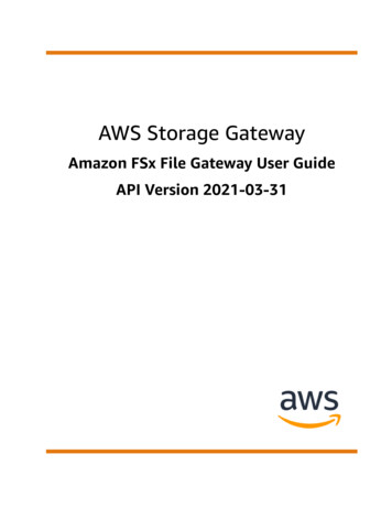
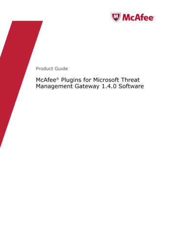
RadioPro IP GatewayInstallation and Configuration Guide for MOTOTRBOStep 1a. for Motorola XPR 45XX & 55XX (Voice):Configure Control Station Radio (For Voice) using MOTOTRBO CPSFollow the 9 steps in this section to configure Control Station Radios for both Voice and Data operation.Use MOTOTRBO CPS (Motorola’s Customer Programming Software) to configure MOTOTRBO radio parametersusing the following steps. (CTI Cable S2-61431 may be used for programming instead of the Motorola programmingcable.)1.From the View menu, choose Expert.2.General Settings folder:a.The Radio IDs of the Voice Radio and the Data Revert Radio that share a RadioPro IP Gateway must be thesame.b.Disable GPS.2a bc. In the Microphone section, change Analog Mic AGC and Digital Mic AGC to Unchecked.2c.7
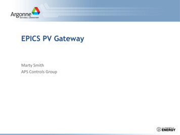
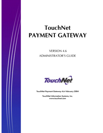
RadioPro IP Gatewayd.Installation and Configuration Guide for MOTOTRBOIn the Persistent LRRP Requests section, verify that Save and Delete parameters are Unchecked.2d.3.Accessories folder:a.Change Ignition Sense to On/Off Or Ignition.b.Change Analog Rear Mic Gain to 10db. (This setting is not needed for a Data Revert Radio.)c.Change Digital Rear Mic Gain to 10db. (This setting is not needed for a Data Revert Radio.)Note: The above mentioned ‘Rear Mic Gain Settings’ may tolerate minor adjustments to optimize mic audiolevels.Warning: Do not set levels outside the range of 9db to 11db, or adverse audio quality will be theresult!d.Change Cable Type to Rear PC and Audio.3a3b & c.3d.8
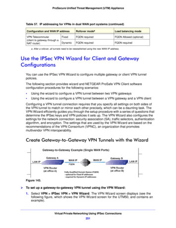
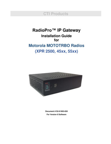
RadioPro IP Gateway4.Installation and Configuration Guide for MOTOTRBONetwork folder:a.Typically, the factory default Radio IP Address programmed into the Control Station radios ‘Network’ tab,does not need to be changed. However, it must be on a different subnet than the RadioPro IP Gateway that isconnected to it via the Rear Accessory Connector. See 4.1 Appendix - IP Addressing on page 30 for moreinformation.For radios sharing an IP Gateway, the following rules must be met:i. All radios sharing an IP Gateway MUST have the SAME Radio ID.ii. All radios sharing an IP Gateway MUST be on DIFFERENT IP subnets.See RadioPro System Planner for Motorola MOTOTRBO for more details and system diagrams.iii. The IP address of the Voice Radio must be LOWER than the IP addresses of the GPS DataRevert Radio(s).4a.b.Change Forward to PC to Via USB. This step is required for the Text Message function when usingRadioPro Dispatch, Solo, Talk, or Talk for Mobile client.4b.c. The ARS Radio ID and TMS Radio ID fields MUST be blank.4c.4c.9
RadioPro IP Gateway5.Installation and Configuration Guide for MOTOTRBOSignaling Systems folder:This step is required if a RadioPro client will be sending an emergency indication to other radios. (Also, see Step7d below for required setup of Channels folder.)Right-Click MDC, Digital, or Capacity Plus, depending on type of channel(s) programmed in radio. Then clickAdd, and then System. Choose appropriate parameters for the Signaling System being added.5a.6.Contacts folder:a.Right-Click MDC, Digital, or Capacity Plus, depending on type of channel programmed in radio. Thenclick Add, Group Call, and then enter the Call ID (Group ID programmed in radio). This step is required forGroup Calls.b.Right-Click MDC, Digital, or Capacity Plus, depending on type of channel programmed in radio. Thenclick Add, and then All Call. This step is required for the All-Call function when using RadioPro Dispatch.6a.10
RadioPro IP Gateway7.Installation and Configuration Guide for MOTOTRBOChannels folder:a)For each Digital channel, change the ARS parameter to Unchecked.7a.7b & c7d.b) If this is a Data Revert control station radio, and if the repeater for this channel has the Enhanced GPSOption enabled, then enable the Enhanced GPS parameter. If this is a Voice control station, thenchange the Enhanced GPS parameter to Unchecked.c)If Enhanced GPS is enabled in step b. above, then set the Window Size to 5 normally or 6, if usingthe selection for Privacy Type. Note that the Window Size parameter is system-wide and must alsobe set in the Data Revert Repeater(s) to match this value. See the tables below for more details.In the following Enhanced GPS Radio Update Tables, the number of radio GPS updates is indicatedbased on selection criteria of Update Interval and Window Reservation.11
RadioPro IP GatewayInstallation and Configuration Guide for MOTOTRBOEnhanced GPS Radio Update TablesWindow Size 5, Privacy Type must be commended)30 sec907560451 min180150120902 min360200240184 min7206004803608 min1440120096072075%60%45%Window Size 6, Privacy Type is Basic or erval30 sec746249371 min14812498742 min2962481961484 min5924963922968 min1184992784592d) For each Digital channel, enable Compressed UDP Data Header by choosing MSI.e)If this control station radio will be used ONLY to collect GPS location data using a Data Revert repeaterslot, then change the RX Only parameter to Checked.7e.12
RadioPro IP Gatewayf)Installation and Configuration Guide for MOTOTRBOThis step is required if a RadioPro Dispatch client will be sending an emergency indication to other radios.(Also see Step 5a above for required setup of Signaling Systems folder.)In the TX section, choose an Emergency System (for digital channels) or Signaling System (foranalog channels).This step is required for the All-Emergency function when using RadioPro Dispatch client.7f.7f.g) In the TX section for each Digital channel, change the Data Call Confirmed parameter to Unchecked.7g.13
RadioPro IP GatewayInstallation and Configuration Guide for MOTOTRBOAdditional CPS Setup for Connect Plus ChannelsIn a Connect Plus radio, the Connect Plus Option Board is configured with the various Talk Groups for the radiosystem. The Connect Plus Option Board CPS must be used to configure these various Talk Groups, or “Zones”.However, for a radio that is used as a control station, since the Connect Plus Option Board cannot pass thisinformation out the rear connector, an application (such as RadioPro Dispatch, Solo, Talk, or Talk for Mobile) doesnot have knowledge of these Connect Plus “Zones” (talk groups).Further, MOTOTRBO CPS is used to configure a radio for only one digital “Channel”, i.e., “Transportation”.Control of the talk group selection is passed to the Option Board by enabling two options described in Step 7hbelow.In order to allow selection of a talk group from a RadioPro client, the following configuration must be performed fora Control Station radio using MOTOTRBO CPS.h) In the Channels folder, add a quantity of channels to match the number of zones configured in theConnect Plus Option Board. In the following screen shot, Channel1, Channel2, etc., have been addedto match the number of “Zones” configured in the Connect Plus Option Board. The Channel Names arenot important since these names are not transferred out of the rear connector of the control station radio;only the generic names of “Channel1”, “Channel2”, etc. will be sent to a RadioPro client.i)For each of the added channels, enable both the Option Board and Option Board Trunkingparameters. It is not necessary to change any other parameters.7h.7i.After writing the CPS configuration to the control station radio, the radio will send messages to theRadioPro IP Gateway and indicate that the radio has been programmed for the “additional” talk groups.ICU.exe can be used to view and configure the IP Gateway for zones and channels as follows:i. Use the Zones/Channels tab in ICU.exe to view Channel names as they will appear inRadioPro clients. By default, they will be generically named “Channel1”, Channel2”, etc.ii. If it is desired to display more descriptive channel names, right-click on a channel name to edit it.iii. If it is desired that a channel or zone is not displayed in a RadioPro client, click on the zone orchannel, and then uncheck the Visible parameter near the bottom of this tab page.iv. Write the new configuration to the RadioPro IP Gateway by choosing Write Settings from theGateway menu.8.Writing CPS Parameters to Radio:After writing the CPS parameters to the MOTOTRBO Control Station radio, remove the programming cable fromthe Control Station radio. A programming cable connected to the front mic connector on the Control Station radiowill prevent communications to a RadioPro IP Gateway from the Rear Accessory Connector. Therefore, when acable is connected to the Rear Accessory Connector to connect a RadioPro IP Gateway or a PC (duringprogramming), ensure that the programming cable has been disconnected from the front mic connector.14
RadioPro IP GatewayInstallation and Configuration Guide for MOTOTRBOSummary of MOTOTRBO CPS Setup for Control Station RadiosFolderSub-FolderParameterStep #GeneralSettingsMainRadio ID2a.Voice Radio and Data Revert Radio that share an IPGateway must have the same Radio IDMainGPS2b.DisableMicrophoneAnalog Mic AGC2c.DisableMicrophoneDigital Mic AGC2c.DisablePersistent LRRPSave2d.DisablePersistent LRRPDelete2d.DisableMainIgnition Sense3a.“On/Off” Or “Ignition”MainAnalog Rear MicGain3b. 10dB: May need to be adjusted for appropriateaudio level transmitted from RadioPro client.Data Revert radio does not require this.MainDigital Rear MicGain3c. 10dB: May need to be adjusted for appropriateaudio level transmitted from RadioPro client.Data Revert radio does not require this.MainCable Type3d.“Rear PC and ChannelsSettingMainRadio IP4a.For radios sharing an IP Gateway, the IP address ofthe Voice Radio must be lower (and in a differentsubnet) than the IP addresses of the Data RevertRadios.An IP Gateway and all radios connected to it musthave unique subnets.Radio NetworkForward to PC4b.“Via USB”ServicesARS Radio ID4c.Leave this field blank (ARS disabled)ServicesTMS Radio ID4c.Leave this field blank (TMS disabled)MDC, Digital, orCapacity PlusSystem5a.Choose appropriate parameters for the signalingsystem being added for All-Emergency function.Data Revert radio does not require this.MDC, Digital, orCapacity Plusadd Group Call6a.Add Group Call contact for the Group Call function.Data Revert radio does not require this.add All Call6b.Add All-Call contact for the All-Call function.Data Revert radio does not require this.DigitalARS7a.Disable for all channelsDigitalEnhanced GPS7b.Enable if this control station is a data revert radioDigitalWindow Size7c.5 if Privacy Type is “None”6 if Privacy Type is “Basic” or “Enhanced”DigitalCompressed UDPData Header7d.“MSI” for all channelsDigital or AnalogRX Only7e.Enable for a data revert radio that will ONLY receiveGPS location data from a data revert repeater slot.Digital or AnalogEmergency System7f.Choose appropriate Emergency ID for AllEmergency function.Data Revert radio does not require this.DigitalData CallConfirmed7g.Disable for all channelsConnect PlusOption Board7h.Enable for all Connect Plus talk groups.Data Revert radio does not require this.Connect PlusOption BoardTrunking7i.Enable for all Connect Plus talk groups.Data Revert radio does not require this15
RadioPro IP GatewayInstallation and Configuration GuideStep 1b. for Motorola XPR 45XX & 55XX (DATA):Configure Control Station Radio (For Data) using MOTOTRBO CPSSAME AS THE PREVIOUS STEPSFollow the previous process starting at 1a on page 7
RadioPro IP GatewayInstallation and Configuration Guide for MOTOTRBOStep 1c. for Motorola XPR 45XX / 55XX Connect Plus Radios :Configure MOTOTRBO Connect Plus Option BoardIf this Control Station radio is being used in a Connect Plus system, then the Connect Plus Option Board must also beconfigured. Use Connect Plus Option Board CPS version R01.30.100 (or later) to configure the Option Board using thefollowing steps. (CTI Cable S2-61431 may be used as a programming cable in lieu of the Motorola programmingcable.)1.General - Menu folder:a.b.In the Contacts section, enable the following parameters:Call Alert, Manual Dial, Radio Check, RemoteMonitor, Radio Enable, and Radio Disable.1a.In the Call Log section, enable the following parameters:Missed, Answered, and Outgoing.1b.2.Write the CPS parameters to the Connect Plus Option Board.CTI Cable S2-61431 may be used as a programming cable inlieu of the Motorola programming cable.3.Remove the programming cable from the Control Station radio.A programming cable connected to the front mic connector on the Control Station radio will preventcommunications to a RadioPro IP Gateway from the Rear Accessory Connector. Therefore, when a cable isconnected to the Rear Accessory Connector to connect a RadioPro IP Gateway or a PC (during programming),ensure that the programming cable has been disconnected from the front mic connector.FolderSectionParameterStep #MenuContactsCall Alert1a.EnableManual Dial1a.EnableRadio Check1a.EnableRemote Monitor1a.EnableRadio Enable1a.EnableRadio tgoing1b.EnableCall Log17Setting
RadioPro IP GatewayInstallation and Configuration Guide for MOTOTRBOStep 1d. for Motorola MOTOTRBO Subscriber Radios:Configure Subscriber Radios for ARS, GPS, and TMSThis step is required if ARS, GPS, or Text Messaging Service is needed at the RadioPro client (such as Dispatch, Solo,Talk, or Talk for Mobile). This step is not required for a Connect Plus system, since these functions are not availableusing a Control Station interface.Use MOTOTRBO CPS (Motorola’s Customer Programming Software) to configure MOTOTRBO radio parametersusing the following steps.1.From the View menu, choose Expert.2.General Settings folder:a.Change the GNSS parameter to Checked.2a.18
RadioPro IP Gatewayb.Installation and Configuration Guide for MOTOTRBOIn the Persistent LRRP Requests section, verify that Save and Delete parameters areUnchecked.2b.3.Network folder:a.Enter the ARS Radio ID. This should be the Radio ID of the Control Station radio that is connected tothe RadioPro IP Gateway.b.Enter the TMS Radio ID. This should be the Radio ID of the Control Station radio that is connected tothe RadioPro IP Gateway.3a.3b.19
RadioPro IP Gateway4.Installation and Configuration Guide for MOTOTRBOChannels folder:Make the following changes for each digital channel that will be used to transmit GPS coordinates:a.Set Scan/Roam List to None. (ARS and GPS will not function if Scan is enabled with a Scan List.)b.Set ARS to On System Change.c.For Data Revert channels, and if the repeater for this channel has the Enhanced GNSS Option enabled, enable theEnhanced GNSS parameter.4b.4c & d4ed.If Enhanced GPS is enabled in step c. above, then set the Window Size to either 5 or 6, depending on theselection for Privacy Type. Note that the Window Size parameter is system-wide and must also be set in theData Revert Repeater(s) to match this value. See the tables on page 17 for more details.e.Set the Compressed UDP Data Header parameter to MSIf.In the TX section of this channel, change GPS Revert to one of the following:- If this radio will use a Data Revert repeater slot to send GPS data to a RadioPro client, then change this parameterto the appropriate Channel Name.- If there is no Data Revert repeater slot, then change this parameter to Selected.g.Disable the Data Call Confirmed parameter by changing it to Unchecked. If this parameter is greyed-out, thenensure that the Enhanced GPS parameter is disabled (Unchecked).4f4g20
RadioPro IP Gateway5.Installation and Configuration Guide for MOTOTRBOWrite the CPS parameters to the MOTOTRBO Control Station radio.Summary of MOTOTRBO CPS Setup for Subscriber RadiosFolderGeneralSettingsSub-FolderParameterStep nelsDigital2b.Save2b.DeleteSettingEnable (if applicable)DisableDisableMust match Radio ID of control stationconnected to IP GatewayMust match Radio ID of control stationconnected to IP Gateway“None”(ARS and GPS will not function if Scan isenabled)ARS Radio ID3a.TMS Radio ID3b.Scan/Roam List4a.ARS4b.Enhanced GPS4c.Window Size4d.Compressed UDPData Header4e.“MSI”GPS Revert4f.If no Data Revert: “Selected”If Data Revert: “Channel Name” of DataRevert ChannelData CallConfirmed4g.Disable21“On System Change”Enable if this control station is a data revertradio5 if Privacy Type is “None”6 if Privacy Type is “Basic” or “Enhanced”
RadioPro IP GatewayInstallation and Configuration Guide for MOTOTRBOStep 1e. for Motorola XPR 2500 Radio:Configure Control Station Radio (For Voice) using MOTOTRBO CPSUse this section to configure Control Station Radios for Voice.Use MOTOTRBO CPS (Motorola’s Customer Programming Software) to configure MOTOTRBO radio parameters viathe following steps.Note: (CTI Cable S2-61916 may be used as a programming cable in place of the Motorolaprogramming cable.)6.From the View menu, choose Expert.7.General Settings folder:a. The Radio IDs of both the Voice Radio and Data Revert Radio that share a RadioPro IP Gateway must bethe same.b. In the Microphone section, be sure to Uncheck the Analog Mic AGC and Digital Mic AGC.c. In the Persistent LRRP Requests section, verify that Save and Delete parameters are Unchecked.22
RadioPro IP Gateway8.Installation and Configuration Guide for MOTOTRBOGeneral - Accessories folder:a. Change Ignition Sense to On/Off Or Ignition.b. Change Analog Rear Mic Gain to 10db. (This setting is not needed for a Data Revert Radio.)c. Change Digital Rear Mic Gain to 10db. (This setting is not needed for a Data Revert Radio.)Note: The above mentioned ‘Rear Mic Gain Settings’ may tolerate minor adjustments to optimize micaudio levels.Warning: Do not set levels outside the range of 9db to 12db, as severe audio quality will result!9.Network folder:Typically, the factory default IP Address programmed into the XPR 2500 Control Station radio does not need to bechanged. However, when it is connected to a RadioPro IP Gateway via the Rear Accessory Connector, it must be on adifferent subnet than that gateway. See 4.1 Appendix - IP Addressing on page 30 for more information.For radios sharing an IP Gateway, the following conditions must be met:i. All radios sharing an IP Gateway MUST have the SAME Radio ID.ii. All radios sharing an IP Gateway MUST be on DIFFERENT IP subnets.See RadioPro System Planner for Motorola MOTOTRBO for more details and system diagrams.iii. The IP address of the Voice Radio must be LOWER than the IP addresses of the GPS DataRevert Radio(s).23
RadioPro IP GatewayInstallation and Configuration Guide for MOTOTRBOiv. Change Forward to PC to Via USB. This step is required for the Text Message functionwhen using RadioPro Dispatch, Solo, Talk, or Talk for Mobile client.The ARS Radio ID and TMS Radio ID fields MUST be blank.10. Signaling Systems folder:This step is required, if a RadioPro client will be sending an emergency indication to other radios. Also, see Step 7below for required setup of Channels folder.)Right-Click MDC or Digital depending on type of channel(s) programmed in radio. Click Add, and then clickSystem. Choose appropriate parameters for the Signaling System being added.24
RadioPro IP GatewayInstallation and Configuration Guide for MOTOTRBO11. Contacts folder:a.Right-Click MDC or Digital, depending on type of channel programmed in radio. Then clickAdd, Group Call, and then enter the Ca
Motorola MOTOTRBO in Conventional, IPSC, Cap , or LCP 1.08.0 CPS Motorola MOTOTRBO in Connect Plus mode 2.2.0 CPS Motorola MOTOTRBO Connect Plus Option Board 1.3.0 CPS 1.2.3 Radio Programming Cable Either the Motorola programming cable or the RadioPro Gateway cable may be used with the CPS software to configure the Control Station radio.