Transcription
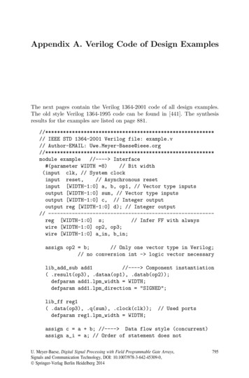
Appendix A. Verilog Code of Design ExamplesThe next pages contain the Verilog 1364-2001 code of all design examples.The old style Verilog 1364-1995 code can be found in [441]. The synthesisresults for the examples are listed on page *************// IEEE STD 1364-2001 Verilog file: example.v// Author-EMAIL: *********************************module example//---- Interface#(parameter WIDTH 8)// Bit width(input clk, // System clockinput reset,// Asynchronous resetinput [WIDTH-1:0] a, b, op1, // Vector type inputsoutput [WIDTH-1:0] sum, // Vector type inputsoutput [WIDTH-1:0] c, // Integer outputoutput reg [WIDTH-1:0] d); // Integer output// -----reg [WIDTH-1:0] s;// Infer FF with alwayswire [WIDTH-1:0] op2, op3;wire [WIDTH-1:0] a in, b in;assign op2 b;// Only one vector type in Verilog;// no conversion int - logic vector necessarylib add sub add1//---- Component instantiation( .result(op3), .dataa(op1), .datab(op2));defparam add1.lpm width WIDTH;defparam add1.lpm direction "SIGNED";lib ff reg1( .data(op3), .q(sum), .clock(clk));defparam reg1.lpm width WIDTH;// Used portsassign c a b; //---- Data flow style (concurrent)assign a i a; // Order of statement does notU. Meyer-Baese, Digital Signal Processing with Field Programmable Gate Arrays,Signals and Communication Technology, DOI: 10.1007/978-3-642-45309-0, Springer-Verlag Berlin Heidelberg 2014795
796Verilog Codeassign b i b; // matter in concurrent code//---- Behavioral stylealways @(posedge clk or posedge reset)begin : p1// Infer registerreg [WIDTH-1:0] s;if (reset) begins 0; d 0;end else begin//s s a i;// Signal assignment statement// d s;s s b i;d **************************// IEEE STD 1364-2001 Verilog file: fun text.v// Author-EMAIL: *********************************// A 32 bit function generator using accumulator and ROM// -----module fun text//---- Interface#(parameter WIDTH 32) // Bit width(input clk,// System clockinput reset,// Asynchronous resetinput [WIDTH-1:0] M, // Accumulator incrementoutput reg [7:0] sin,// System sine outputoutput [7:0] acc);// Accumulator MSBs// -----reg [WIDTH-1:0] acc32;wire [7:0]msbs;// Auxiliary vectorsreg [7:0] rom[255:0];always @(posedge clk or posedge reset)if (reset 1)acc32 0;else beginacc32 acc32 M; //-- Add M to acc32 andend//-- store in registerassign msbs acc32[WIDTH-1:WIDTH-8];
Verilog Codeassign acc797 msbs;initialbegin readmemh("sine256x8.txt", rom);endalways @ (posedge clk)beginsin *******************************// IEEE STD 1364-2001 Verilog file: cmul7p8.v// Author-EMAIL: *********************************module cmul7p8// ------ Interface(input signed [4:0] x,// System inputoutput signed [4:0] y0, y1, y2, y3);// The 4 system outputs y 7*x/8// -----assign y0 7 * x / 8;assign y1 x / 8 * 7;assign y2 x/2 x/4 x/8;assign y3 x - **********************// IEEE STD 1364-2001 Verilog file: add1p.v// Author-EMAIL: *********************************module add1p#(parameter WIDTH 19, // Total bit widthWIDTH1 9, // Bit width of LSBsWIDTH2 10) // Bit width of MSBs(input [WIDTH-1:0] x, y, // Inputsoutput [WIDTH-1:0] sum, // Resultinputclk, // System clockoutputLSBs carry); // Test portreg [WIDTH1-1:0] l1, l2, s1; // LSBs of inputs
798Verilog Codereg [WIDTH1:0] r1;// LSBs of inputsreg [WIDTH2-1:0] l3, l4, r2, s2; // MSBs of input// -----always @(posedge clk) begin// Split in MSBs and LSBs and store in registers// Split LSBs from input x,yl1[WIDTH1-1:0] x[WIDTH1-1:0];l2[WIDTH1-1:0] y[WIDTH1-1:0];// Split MSBs from input x,yl3[WIDTH2-1:0] x[WIDTH2-1 WIDTH1:WIDTH1];l4[WIDTH2-1:0] y[WIDTH2-1 WIDTH1:WIDTH1];/************* First stage of the adder *****************/r1 {1’b0, l1} {1’b0, l2};r2 l3 l4;/************** Second stage of the adder ****************/s1 r1[WIDTH1-1:0];// Add MSBs (x y) and carry from LSBss2 r1[WIDTH1] r2;endassign LSBs carry r1[WIDTH1]; // Add a test signal// Build a single registered output word// of WIDTH WIDTH1 WIDTH2assign sum {s2, **********************// IEEE STD 1364-2001 Verilog file: add2p.v// Author-EMAIL: *********************************// 22-bit adder with two pipeline stages// uses no componentsmodule add2p#(parameter WIDTH 28,// Total bit widthWIDTH1 9,// Bit width of LSBsWIDTH2 9,// Bit width of middleWIDTH12 18,// Sum WIDTH1 WIDTH2WIDTH3 10)// Bit width of MSBs(input [WIDTH-1:0] x, y,// Inputsoutput [WIDTH-1:0] sum,// Resultoutput LSBs carry, MSBs carry, // Carry test bitsinputclk);// System clock// ------
Verilog :0][WIDTH2:0][WIDTH3-1:0]l1,q1;l3,q2,l5,799l2, v1, s1; // LSBs of inputs// LSBs of inputsl4, s2;// Middle bitsv2;// Middle bitsl6, q3, v3, s3; // MSBs of input// Split in MSBs and LSBs and store in registersalways @(posedge clk) begin// Split LSBs from input x,yl1[WIDTH1-1:0] x[WIDTH1-1:0];l2[WIDTH1-1:0] y[WIDTH1-1:0];// Split middle bits from input x,yl3[WIDTH2-1:0] x[WIDTH2-1 WIDTH1:WIDTH1];l4[WIDTH2-1:0] y[WIDTH2-1 WIDTH1:WIDTH1];// Split MSBs from input x,yl5[WIDTH3-1:0] x[WIDTH3-1 WIDTH12:WIDTH12];l6[WIDTH3-1:0] y[WIDTH3-1 WIDTH12:WIDTH12];//************** First stage of the adder ****************q1 {1’b0, l1} {1’b0, l2}; // Add LSBs of x and yq2 {1’b0, l3} {1’b0, l4}; // Add LSBs of x and yq3 l5 l6;// Add MSBs of x and y//************* Second stage of the adder *****************v1 q1[WIDTH1-1:0];// Save q1// Add result from middle bits (x y) and carry from LSBsv2 q1[WIDTH1] {1’b0,q2[WIDTH2-1:0]};// Add result from MSBs bits (x y) and carry from middlev3 q2[WIDTH2] q3;//************* Third stage of the adder ******************s1 v1;// Save v1s2 v2[WIDTH2-1:0];// Save v2// Add result from MSBs bits (x y) and 2. carry from middles3 v2[WIDTH2] v3;endassign LSBs carry q1[WIDTH1]; // Provide test signalsassign MSBs carry v2[WIDTH2];// Build a single output word of WIDTH WIDTH1 WIDTH2 WIDTH3assign sum {s3, s2, s1};// Connect sum to output **********************// IEEE STD 1364-2001 Verilog file: add3p.v
800Verilog Code// Author-EMAIL: *********************************// 37-bit adder with three pipeline stage// uses no componentsmodule add3p#(parameter WIDTH 37, // Total bit widthWIDTH0 9, // Bit width of LSBsWIDTH1 9, // Bit width of 2. LSBsWIDTH01 18, // Sum WIDTH0 WIDTH1WIDTH2 9, // Bit width of 2. MSBsWIDTH012 27, // Sum WIDTH0 WIDTH1 WIDTH2WIDTH3 10) // Bit width of MSBs(input [WIDTH-1:0] x, y, // Inputsoutput [WIDTH-1:0] sum, // Resultoutput LSBs Carry, Middle Carry, MSBs Carry, // Test pinsinputclk); // Clock// -----reg [WIDTH0-1:0] l0, l1, r0, v0, s0;// LSBs of inputsreg [WIDTH0:0] q0;// LSBs of inputsreg [WIDTH1-1:0] l2, l3, r1, s1;// 2. LSBs of inputreg [WIDTH1:0] v1, q1;// 2. LSBs of inputreg [WIDTH2-1:0] l4, l5, s2, h7;// 2. MSBs bitsreg [WIDTH2:0] q2, v2, r2;// 2. MSBs bitsreg [WIDTH3-1:0] l6, l7, q3, v3, r3, s3, h8;// MSBs of inputalways @(posedge clk) begin// Split in MSBs and LSBs and store in registers// Split LSBs from input x,yl0[WIDTH0-1:0] x[WIDTH0-1:0];l1[WIDTH0-1:0] y[WIDTH0-1:0];// Split 2. LSBs from input x,yl2[WIDTH1-1:0] x[WIDTH1-1 WIDTH0:WIDTH0];l3[WIDTH1-1:0] y[WIDTH1-1 WIDTH0:WIDTH0];// Split 2. MSBs from input x,yl4[WIDTH2-1:0] x[WIDTH2-1 WIDTH01:WIDTH01];l5[WIDTH2-1:0] y[WIDTH2-1 WIDTH01:WIDTH01];// Split MSBs from input x,yl6[WIDTH3-1:0] x[WIDTH3-1 WIDTH012:WIDTH012];l7[WIDTH3-1:0] y[WIDTH3-1 WIDTH012:WIDTH012];//************* First stage of the adder *****************q0 {1’b0, l0} {1’b0, l1}; // Add LSBs of x and y
Verilog Code801q1 {1’b0, l2} {1’b0, l3}; // Add 2. LSBs of x / yq2 {1’b0, l4} {1’b0, l5}; // Add 2. MSBs of x/yq3 l6 l7;// Add MSBs of x and y//************* Second stage of the adder *****************v0 q0[WIDTH0-1:0];// Save q0// Add result from 2. LSBs (x y) and carry from LSBsv1 q0[WIDTH0] {1’b0, q1[WIDTH1-1:0]};// Add result from 2. MSBs (x y) and carry from 2. LSBsv2 q1[WIDTH1] {1’b0, q2[WIDTH2-1:0]};// Add result from MSBs (x y) and carry from 2. MSBsv3 q2[WIDTH2] q3;//************** Third stage of the adder *****************r0 v0; // Delay for LSBsr1 v1[WIDTH1-1:0]; // Delay for 2. LSBs// Add result from 2. MSBs (x y) and carry from 2. LSBsr2 v1[WIDTH1] {1’b0, v2[WIDTH2-1:0]};// Add result from MSBs (x y) and carry from 2. MSBsr3 v2[WIDTH2] v3;//************ Fourth stage of the adder ******************s0 r0;// Delay for LSBss1 r1;// Delay for 2. LSBss2 r2[WIDTH2-1:0]; // Delay for 2. MSBs// Add result from MSBs (x y) and carry from 2. MSBss3 r2[WIDTH2] r3;endassign LSBs Carry q0[WIDTH1];assign Middle Carry v1[WIDTH1];assign MSBs Carry r2[WIDTH2];// Provide test signals// Build a single output word of// WIDTH WIDTH0 WIDTH1 WIDTH2 WIDTH3assign sum {s3, s2, s1, s0}; // Connect sum to ************************// IEEE STD 1364-2001 Verilog file: div res.v// Author-EMAIL: *********************************// Restoring Division// Bit width: WNWDWNWD//Nominator / Denumerator Quotient and Remainder
802Verilog Code// OR:Nominator Quotient * Denumerator Remainder// -----module div res//------ Interface(input clk,// System clockinput reset,// Asynchron resetinput [7:0] n in,// Nominatorinput [5:0] d in,// Denumeratoroutput reg [5:0] r out,// Remainderoutput reg [7:0] q out); // Quotient// -----reg [1:0] state;// FSM stateparameter ini 0, sub 1, restore 2, done 3; // State// assignments// Divider in behavioral stylealways @(posedge clk or posedge reset)begin : States // Finite state machinereg [3:0] count;regregreg[13:0] d;// Double bit width unsignedsigned [13:0] r; // Double bit width signed[7:0] q;if (reset) begin// Asynchronous resetstate ini; count 0;q 0; r 0; d 0; q out 0; r out 0;end elsecase (state)ini : begin// Initialization stepstate sub;count 0;q 0;// Reset quotient registerd d in 7;// Load aligned denumeratorr n in;// Remainder nominatorendsub : begin// Processing stepr r - d;// Subtract denumeratorstate restore;endrestore : begin// Restoring stepif (r 0) begin // Check r 0r r d;// Restore previous remainderq q 1;// LSB 0 and SLLendelse
Verilog Code803q (q 1) 1; // LSB 1 and SLLcount count 1;d d 1;if (count 8)// Division ready ?state done;elsestate sub;enddone : begin// Output of resultq out q[7:0];r out r[5:0];state ini;// Start next ***************************************// IEEE STD 1364-2001 Verilog file: div aegp.v// Author-EMAIL: *********************************// Convergence division after//Anderson, Earle, Goldschmidt, and Powers// Bit width: WNWDWNWD//Nominator / Denumerator Quotient and Remainder// OR:Nominator Quotient * Denumerator Remainder// -----module div aegp(input clk,// System clockinput reset,// Asynchron resetinput [8:0] n in,// Nominatorinput [8:0] d in,// Denumeratoroutput reg [8:0] q out); // Quotient// -----reg [1:0] state;always @(posedge clk or posedge reset) //- Divider inbegin : States// behavioral styleparameter s0 0, s1 1, s2 2;reg [1:0] count;reg [9:0] x, t, f;reg [17:0] tempx, tempt;// one guard bit
804Verilog Codeif (reset) begin// Asynchronous resetstate s0; q out 0; count 0; x 0; t 0;end elsecase (state)s0 : begin// Initialization stepstate s1;count 0;t {1’b0, d in};// Load denumeratorx {1’b0, n in};// Load nominatorends1 : begin// Processing stepf 512 - t;// TWO - ttempx (x * f); // Product in fulltempt (t * f); // bitwidthx tempx 8; // Factional ft tempt 8; // Scale by 256count count 1;if (count 2)// Division ready ?state s2;elsestate s1;ends2 : begin// Output of resultq out x[8:0];state s0;// Start next ***************************************// IEEE STD 1364-2001 Verilog file: cordic.v// Author-EMAIL: *********************************module cordic #(parameter W 7) // Bit width - 1(input clk,// System clockinput reset,// Asynchronous resetinput signed [W:0] x in,// System real or x inputinput signed [W:0] y in,// System imaginary or y inputoutput reg signed [W:0] r, // Radius resultoutput reg signed [W:0] phi,// Phase resultoutput reg signed [W:0] eps);// Error of results// ------
Verilog Code805// There is bit access in Quartus array types// in Verilog 2001, therefore use single vectors// but use a separate lines for each array!reg signed [W:0] x [0:3];reg signed [W:0] y [0:3];reg signed [W:0] z [0:3];always @(posedge reset or posedge clk) begin : P1integer k; // Loop variableif (reset) begin// Asynchronous clearfor (k 0; k 3; k k 1) beginx[k] 0; y[k] 0; z[k] 0;endr 0; eps 0; phi 0;end else beginif (x in 0)// Test for x in 0 rotatebegin// 0, 90, or -90 degreesx[0] x in; // Input in register 0y[0] y in;z[0] 0;endelse if (y in 0)beginx[0] y in;y[0] - x in;z[0] 90;endelsebeginx[0] - y in;y[0] x in;z[0] -90;endif (y[0]beginx[1]y[1]z[1]endelsebeginx[1] 0) x[0] y[0]; y[0] - x[0]; z[0] 45; x[0] - y[0];// Rotate 45 degrees
806Verilog Codey[1] y[0] x[0];z[1] z[0] - 45;endif f (y[2]beginx[3]y[3]z[3]endelsebeginx[3]y[3]z[3]end 0)// Rotate 26 degrees x[1] (y[1] 1); // i.e. x[1] y[1]/2 y[1] - (x[1] 1); // i.e. y[1]-x[1]/2 z[1] 26; x[1] - (y[1] 1); // i.e. x[1]-y[1]/2 y[1] (x[1] 1); // i.e. y[1] x[1]/2 z[1] - 26; 0)// Rotate 14 degrees x[2] (y[2] 2); // i.e. x[2] y[2]/4 y[2] - (x[2] 2); // i.e. y[2]-x[2]/4 z[2] 14; x[2] - (y[2] 2); // i.e. x[2]-y[2]/4 y[2] (x[2] 2); // i.e. y[2] x[2]/4 z[2] - 14;r x[3];phi z[3];eps *****************************// IEEE STD 1364-2001 Verilog file: arctan.v// Author-EMAIL: Uwe.Meyer-Baese@ieee.org// -----module arctan #(parameter W 9,// Bit widthL 5)// Array size(input clk,// System clock
Verilog Code807input reset,// Asynchron resetinput signed [W-1:0] x in, // System input//output reg signed [W-1:0] d o [1:L],output wire signed [W-1:0] d o1, d o2 ,d o3, d o4 ,d o5,// Auxiliary recurrenceoutput reg signed [W-1:0] f out); // System output// -----reg signed [W-1:0] x;// Auxilary signalswire signed [W-1:0] f;wire signed [W-1:0] d [1:L]; // Auxilary array// Chebychev coefficients c1, c2, c3 for 8 bit precision// c1 212; c3 -12; c5 1;always @(posedge clk or posedge reset) beginif (reset) begin // Asynchronous clearx 0; f out 0;end else beginx x in;// FF for input and outputf out f;endend// Compute sum-of-products with// Clenshaw’s recurrence formulaassign d[5] ’sd1;// c5 1assign d[4] (x * d[5]) / 128;assign d[3] ((x * d[4]) / 128) assign d[2] ((x * d[3]) / 128) assign d[1] ((x * d[2]) / 128) assign f ((x * d[1]) / 256) //assign d o1assign d o2assign d o3assign d o4assign d o5endmodule d[1];d[2];d[3];d[4];d[5];d[5] - 12; // c3 -12d[4];d[3] 212; // c1 212d[2];last step is different// Provide test signals as ****************// IEEE STD 1364-2001 Verilog file: ln.v// Author-EMAIL: *********************************module ln #(parameter N 5, // Number of Coefficients-1
808Verilog Codeparameter W 17) // Bitwidth -1(input clk,// System clockinput reset,// Asynchronous resetinput signed [W:0] x in,// System inputoutput reg signed [W:0] f out); // System output// -----reg signed [W:0] x, f;// Auxilary registerwire signed [W:0] p [0:5];reg signed [W:0] s [0:5];// Polynomial// f(x) (1//assign p[0]assign p[1]assign p[2]assign p[3]assign p[4]assign p[5]coefficients for 16 bit precision: 65481 x -32093 x 2 18601 x 3-8517 x 4 1954 x 5)/65536 18’sd1; 18’sd65481; -18’sd32093; 18’sd18601; -18’sd8517; 18’sd1954;always @(posedge clk or posedge reset)begin : Storeif (reset) begin// Asynchronous clearx 0; f out 0;end else beginx x in;// Store input in registerf out f;endendalways @*// Compute sum-of-productsbegin : SOPinteger k; // define the loop variablereg signed [35:0] slv;s[N] p[N];// Polynomial Approximation from Chebyshev coefficientsfor (k N-1; k 0; k k-1)beginslv x * s[k 1]; // no FFs for slvs[k] (slv 16) p[k];end// x*s/65536 problem 32 bitsf s[0];// make visable outsideend
Verilog *************************// IEEE STD 1364-2001 Verilog file: sqrt.v// Author-EMAIL: *********************************module sqrt//---- Interface(input clk,// System clockinput reset,// Asynchronous resetoutput [1:0] count o,// Counter SLLinput signed [16:0] x in,// System inputoutput signed [16:0] pre o,// Prescaleroutput signed [16:0] x o,// Normalized x inoutput signed [16:0] post o,// Postscaleroutput signed [3:0] ind o,// Index to poutput signed [16:0] imm o,// ALU preload valueoutput signed [16:0] a o,// ALU factoroutput signed [16:0] f o,// ALU outputoutput reg signed [16:0] f out); // System output// -----// Define the operation modes:parameter load 0, mac 1, scale 2, denorm 3, nop 4;// Assign the FSM states:parameter start 0, leftshift 1, sop 2,rightshift 3, done 4;reg [3:0] s, op;reg [16:0] x; // Auxilaryreg signed [16:0] a, b, f, imm; // ALU datareg signed [33:0] af; // Product double widthreg [16:0] pre, post;reg signed [3:0] ind;reg [1:0] count;// Chebychev poly coefficients for 16 bit precision:wire signed [16:0] p 3]p[4] 7563;42299;-29129;15813;-3778;always @(posedge reset or posedge clk) //------ SQRT FSMbegin : States// sample at clk rate
810Verilog Codeif (reset) begin// Asynchronous resets start; f out 0; op 0; count 0;imm 0; ind 0; a 0; x 0;end else begincase (s)// Next State assignmentsstart : begin// Initialization steps leftshift; ind 4;imm x in;// Load argument in ALUop load; count 0;endleftshift : begin// Normalize to 0.5 . 1.0count count 1; a pre; op scale;imm p[4];if (count 2) op nop;if (count 3) begin // Normalize ready ?s sop; op load; x f;endendsop : begin// Processing stepind ind - 1; a x;if (ind -1) begin // SOP ready ?s rightshift; op denorm; a post;end else beginimm p[ind]; op mac;endendrightshift : begin // Denormalize to original ranges done; op nop;enddone : begin// Output of resultsf out f;// I/O store in registerop nop;s start;// start next cycleendendcaseendendalways @(posedge reset or posedge clk)begin : ALU// Define the ALU operationsif (reset)// Asynchronous clearf 0;else begin
Verilog Codeaf a * f;case (op)load:mac:scale:denorm :nop:default :endcaseendendffffff 811imm;(af 15) imm;af;af 15;f;f;always @(x in)begin : EXPreg [16:0] slv;reg [16:0] po, pr;integer K; // Loop variableslv x in;// Compute pre-scaling:for (K 0; K 15; K K 1)if (slv[K] 1)pre 1 (14-K);// Compute post scaling:po 1;for (K 0; K 7; K K 1) beginif (slv[2*K] 1)// even 2 k gets 2 k/2po 1 (K 8);// sqrt(2): CSD Error 0.0000208 15.55 effective bits// 1 0. -1 0 -1 0 1 0 1 0 0 0 0 0 1// 97531-5if (slv[2*K 1] 1) // odd k has sqrt(2) factorpo (1 (K 9)) - (1 (K 7)) - (1 (K 5)) (1 (K 3)) (1 (K 1)) (1 (K-5));endpost po;endassignassignassignassignassignassigna o a;// Provide some test signals as outputsimm o imm;f o f;pre o pre;post o post;x o x;
812Verilog Codeassign ind o ind;assign count o ************************// IEEE STD 1364-2001 Verilog file: magnitude.v// Author-EMAIL: *********************************module magnitude(input clk,// System clockinput reset,// Asynchron resetinput signed [15:0] x, y,// System inputoutput reg signed [15:0] r);// System output// -----reg signed [15:0] x r, y r, ax, ay, mi, ma;// Approximate the magnitude via// r alpha*max( x , y ) beta*min( x , y )// use alpha 1 and beta 1/4always @(posedge reset or posedge clk) // Control theif (reset) begin// system sample at clk ratex r 0; y r 0; // Asynchronous clearend else beginx r x; y r y;endalways @* beginax (x r 0)? x r : -x r; // Take absolute values firstay (y r 0)? y r : -y r;if (ax ay) beginmi ay;ma ax;end else beginmi ax;ma ay;endend// Determine max and min valuesalways @(posedge reset or posedge clk)if (reset)// Asynchronous clearr 0;else
Verilog Code813r ma mi/4; // Compute r alpha*max **************************// IEEE STD 1364-2001 Verilog file: fir gen.v// Author-EMAIL: *********************************// This is a generic FIR filter generator// It uses W1 bit data/coefficients bitsmodule fir gen#(parameter W1 9,// Input bit widthW2 18,// Multiplier bit width 2*W1W3 19,// Adder width W2 log2(L)-1W4 11,// Output bit widthL 4)// Filter length(input clk,// System clockinput reset,// Asynchronous resetinput Load x,// Load/run switchinput signed [W1-1:0] x in,// System inputinput signed [W1-1:0] c in,//Coefficient data inputoutput signed [W4-1:0] y out); // System output// -----reg signed [W1-1:0] x;wire signed [W3-1:0] y;// 1D array types i.e. memories supported by Quartus// in Verilog 2001; first bit then vector sizereg signed [W1-1:0] c [0:3]; // Coefficient arraywire signed [W2-1:0] p [0:3]; // Product arrayreg signed [W3-1:0] a [0:3]; // Adder array//---- Load Data or Coefficientalways @(posedge clk or posedge reset)begin: Loadinteger k;// loop variableif (reset) begin// Asynchronous clearfor (k 0; k L-1; k k 1) c[k] 0;x 0;end else if (! Load x) beginc[3] c in; // Store coefficient in registerc[2] c[3];// Coefficients shift onec[1] c[2];c[0] c[1];end else
814Verilog Codex x in; // Get one data sample at a timeend//---- Compute sum-of-productsalways @(posedge clk or posedge reset)begin: SOP// Compute the transposed filter additionsinteger k;// loop variableif (reset)// Asynchronous clearfor (k 0; k 3; k k 1) a[k] 0;else begina[0] p[0] a[1];a[1] p[1] a[2];a[2] p[2] a[3];a[3] p[3]; // First TAP has only a registerendendassign y a[0];genvar I; //Define loop variable for generate statementgeneratefor (I 0; I L; I I 1) begin : MulGen// Instantiate L multipliersassign p[I] x * c[I];endendgenerateassign y out ********************************// IEEE STD 1364-2001 Verilog file: fir srg.v// Author-EMAIL: *********************************module fir srg//---- Interface(input clk,// System clockinput reset,// Asynchronous resetinput signed [7:0] x,// System inputoutput reg signed [7:0] y); // System output// -----// Tapped delay line array of bytesreg signed [7:0] tap [0:3];integer I; // Loop variable
Verilog Code815always @(posedge clk or posedge reset)begin : P1//---- Behavioral Style// Compute output y with the filter coefficients weight.// The coefficients are [-1 3.75 3.75 -1].// Multiplication and division can// be done in Verilog 2001 with signed shifts.if (reset) begin// Asynchronous clearfor (I 0; I 3; I I 1) tap[I] 0;y 0;end else beginy (tap[1] 1) tap[1] (tap[1] 1)- tap[0] ( tap[1] 2) (tap[2] 1) tap[2] (tap[2] 1) (tap[2] 2) - tap[3];for (I 3; I 0; I I-1) begintap[I] tap[I-1]; // Tapped delay line: shift oneendtap[0] x;// Input in register *************************// IEEE STD 1364-2001 Verilog file: case5p.v// Author-EMAIL: *********************************module case5p(inputclk,input [4:0] table in,output reg [4:0] table out);// range 0 to 25// -----reg [3:0] lsbs;reg [1:0] msbs0;reg [4:0] table0out00, table0out01;// These are the distributed arithmetic CASE tables for// the 5 coefficients: 1, 3, 5, 7, 9always @(posedge clk) beginlsbs[0] table in[0];lsbs[1] table in[1];lsbs[2] table in[2];
816Verilog Codelsbs[3] table in[3];msbs0[0] table in[4];msbs0[1] msbs0[0];end// This is the final DA MPX stage.always @(posedge clk) begincase (msbs0[1])0 : table out table0out00;1 : table out table0out01;default : ;endcaseend// This is the DA CASE table 00 out of 1.always @(posedge clk) begincase (lsbs)0 : table0out00 0;1 : table0out00 1;2 : table0out00 3;3 : table0out00 4;4 : table0out00 5;5 : table0out00 6;6 : table0out00 8;7 : table0out00 9;8 : table0out00 7;9 : table0out00 8;10 : table0out00 10;11 : table0out00 11;12 : table0out00 12;13 : table0out00 13;14 : table0out00 15;15 : table0out00 16;default ;endcaseend// This is the DA CASE table 01 out of 1.always @(posedge clk) begincase (lsbs)0 : table0out01 9;1 : table0out01 10;2 : table0out01 12;3 : table0out01 13;
Verilog Code4 : table0out015 : table0out016 : table0out017 : table0out018 : table0out019 : table0out0110 : table0out0111 : table0out0112 : table0out0113 : table0out0114 : table0out0115 : table0out01default ;endcaseend *******// IEEE STD 1364-2001 Verilog file: dasign.v// Author-EMAIL: *********************************‘include "case3s.v" // User defined componentmodule dasign//- Interface(input clk,// System clockinput reset,// Asynchron resetinput signed [3:0] x0 in, // First system inputinput signed [3:0] x1 in, // Second system inputinput signed [3:0] x2 in, // Third system inputoutput [3:0] lut,// DA look-up tableoutput reg signed [6:0] y);// System output// -----reg signed [3:0] x0, x1, x2;wire signed [2:0] table in;wire signed [3:0] table out;reg [0:0] state;assign table in[0] x0[0];assign table in[1] x1[0];assign table in[2] x2[0];always @(posedge clk or posedge reset)// DA in behavioralbegin : P1// styleparameter s0 0, s1 1;
818Verilog Codeinteger k;reg [2:0] count;reg [6:0] p;// Counts the shifts// Temporary registerif (reset) begin// Asynchronous resetstate s0;x0 0; x1 0; x2 0; p 0; y 0;count 0;end elsecase (state)s0 : begin// Initialization stepstate s1;count 0;p 0;x0 x0 in;x1 x1 in;x2 x2 in;ends1 : begin// Processing stepif (count 4) begin// Is sum of product done?y p;// Output of result to y andstate s0;// start next sum of productend else begin //Subtract for last accumulator stepif (count 3)// i.e. p/2 /- table out * 8p (p 1) - (table out 3);else// Accumulation for all other stepsp (p 1) (table out 3);for (k 0; k 2; k k 1) begin// Shift bitsx0[k] x0[k 1];x1[k] x1[k 1];x2[k] x2[k 1];endcount count 1;state s1;endendendcaseendcase3s LC Table0( .table in(table in), .table out(table out));assign lut table out; // Provide test signal
Verilog *************************// IEEE STD 1364-2001 Verilog file: case3s.v// Author-EMAIL: *********************************module case3s(input [2:0] table in, // Three bitoutput reg [3:0] table out); // Range -2 to 4 - 4 bits// -----// This is the DA CASE table for// the 3 coefficients: -2, 3, 1always @(table in)begincase (table in)0 :table out1 :table out2 :table out3 :table out4 :table out5 :table out6 :table out7 :table outdefault : ;endcaseend ************************************// IEEE STD 1364-2001 Verilog file: dapara.v// Author-EMAIL: *********************************‘include "case3s.v" // User define
Appendix A. Verilog Code of Design Examples The next pages contain the Verilog 1364-2001 code of all design examples. The old style Verilog 1364-1995 code can be found in [441]. The synthesis results for the examples are listed on page 881. //***** // IEEE STD 1364-2001 Verilog file: example.v
