Transcription
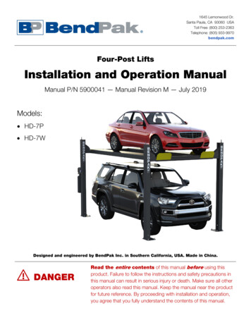
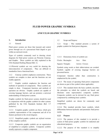
Attention and Warning SymbolsYou must be aware of safety when you install and use this system. This guide provides various procedures.If you do some of these procedures carelessly, you could injure or kill yourself or damage equipment orproperty. Some other procedures require special attention.Marks a procedure where the following may happen: Personal injury or death may occur. Equipment or property may be damaged.Marks the following issues: Important operation or maintenance instructions follow. Special attention is required.Important Safety InstructionsYou must keep safety in mind when you install and use the DISH 1000.4. Refer to the safety instructions inthis guide. In this guide, the following notes tell you when you need to pay special attention:1.2.3.4.Read these instructions.Keep these instructions.Heed all warnings.Follow all instructions.Keep the following in mind when you install the DISH 1000.4: Before you drill any holes in your building, make sure there are no wires or pipes near the holes.Install the equipment in accordance with the local building and electrical codes. If you aren’t sure,call a licensed building inspector or electrician for help.Never install the satellite dish near power lines.Don’t install the satellite dish on composite materials such as strand, chip, fiber, or particle boardunless the fastener attaches securely to a wall stud, rafter, or other foundation material beneath thesurface.Note to Satellite TV System Installer: This reminder is to call the satellite TV system installer’sattention to the guidelines for grounding the system in accordance with the National Electrical Code(NEC) as referenced in Articles 250, 810, and 820. These sections cover the conductor insulation,material, size, length, and connection requirements.Satellite DishCoaxial Cablefrom Satellite DishGround ClampAntenna DischargeUnitGrounding Conductors(NEC Section 810-21)Electric Service EquipmentGround ClampsPower Service GroundingElectrode System(NEC Art. 250, Part H)
Installation InstructionsAttention! These installation instructions are intended for use by qualified professionaltechnicians due to the complexity of the installation and compliance to national/localbuilding and electrical codes.OverviewThese instructions guide you through the installation of a DISH Network DISH 1000.4 antenna, whichconsists of a reflector assembly and a DISH Pro Plus 1000.4 LNBF.The Appendix (page 17) guides you through using the conversion of a DISH 500 antenna to function as aDISH 1000.4.The DISH 1000.4 is capable of receiving digital television signals from three DBS satellite locations:61.5 W, 72.7 W, and 77 W. These instructions cover wall mounting only. For other mounting options (forexample, pole mounting, or non-penetrating mounting), see the Retailer Care Site at retailer.echostar.com.Installation ConsiderationsThe DISH 1000.4 includes enhanced peaking controls for the azimuth and elevation settings that providethe ability to more easily obtain an optimal peaking of the dish antenna. Refer to Figure 1 on page 2 formore details on the enhanced peaking controls.The fine-tune azimuth and elevation settings require the use of an 1/2” wrench. All other nuts and bolts usea 7/16” wrench.All DISH 1000.4 equipment is marked with the circled A symbol shown below to help in identification.DISH Network ViP-series receiver models must have the circled A symbol shown on their Contents andFeatures label to be installed in a DISH 1000.4 system.About the SystemThe DISH Pro Plus 1000.4 LNBF provides reception from the 61.5 W, 72.7 W, and 77 W orbitallocations, and provides an LNBF input port to receive programming from another satellite. The followingLNBF types can be connected to the LNBF input port: DISH Pro Single, DISH Pro Dual, DISH Pro DualBand, or DISH Network bandstacked LNBFs.The LNBF assembly supports connection of up to three satellite receivers in any of the followingcombinations: Single-cable connection to DISH Pro Plus (dual-tuner) receivers, when each input is used with a DISHPro Plus Separator. Single-cable connection to DISH Pro receivers.Page 1
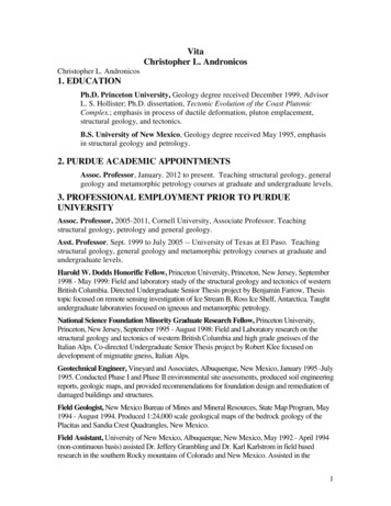
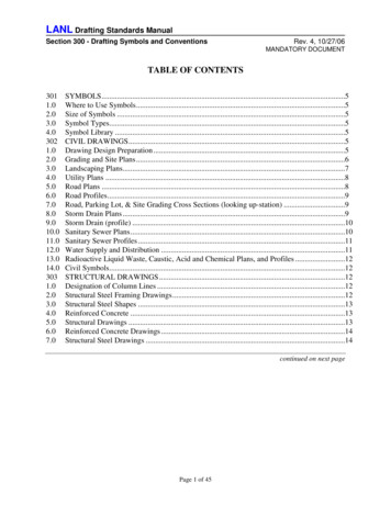
Quick Installation InstructionsSatellite ReflectorReflector BoltsDish MountingBracketSkewScaleElevation RodSkewPointElevationRod NutsSkewBoltsAzimuthPlate and CamElevationScale77 72.7 Azimuth BoltsElevationBolts61.5 Mast BoltsAdapterBracketMast ClampReflector BoltsLNBFArmDrip Loop90 DPP 1000.4 LNBFMastLevelPivot BoltLNB In61.5 Foot72.7 77 To SatelliteReceiver(s)Mast Adjustment BoltFigure 1. DISH 1000.4 Antenna Installation Overview1.2.3.4.5.6.7.8.9.10.11.12.13.14.15.Find Azimuth/Elevation/Skew angles for your location (instructions on page 3 and tables on page 11).Find a location for the dish antenna with a clear line of sight and a sturdy mounting surface (page 3, step 1).Mount the mast, making sure it is absolutely vertical (page 3, steps 2 and 3). Attach struts to the mast, using theinstructions that came with your struts.Assemble the dish antenna, setting the skew and elevation angles in the process (pages 3-4, steps 4-6).Mount the dish antenna on the mast and point the dish to the azimuth angle (page 4, step 7).Run cables between the dish antenna and the receiver(s), leaving a service loop around the dish mounting bracketand attaching cables to the mast using zip ties (page 5, step 1).Using a peaking meter attached to the DPP 1000.4 LNBF PORT 2, rough peak the dish on 72.7 W usingtransponder 19 or 21 for maximum strength. Lock the mast clamp bolts (see Table 1) and re-confirm signal (page5, steps 2 and 3).Note: If using a peaking meter, only odd transponders will be detected from 72.7 W at this time.Using the elevation rod, fine-tune the elevation angle to achieve maximum signal. Tighten the top elevation rodnut, and then tighten the side elevation bolts marked T. Reconfirm signal after tightening all elevation bolts (page6, step 6).Using the azimuth fine-tune cam, fine-tune the azimuth angle to achieve maximum signal. Tighten the boltslabeled with a T and reconfirm signal. Do not tighten the azimuth fine-tune cam (page 7, step 6).Connect the receiver cable(s) to the DPP 1000.4 LNBF PORT 1 (and PORT 2 and PORT 3, as necessary)and receiver (page 7, steps 7-9).Run Check Switch test and confirm 61.5 W, 72.7 W, and 77 W reception (page 8, steps 10 and 11).Take a software download, if you didn’t already (page 8, step 12).Run a second Check Switch test and confirm 61.5ºW, 72.7ºW, and 77 reception (page 8, step 13).Install additional receiver(s), if necessary.If applicable, connect a second satellite dish to the DPP 1000.4 LNBF’s LNB IN port (page 9, steps 1-4).Page 2
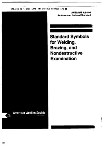
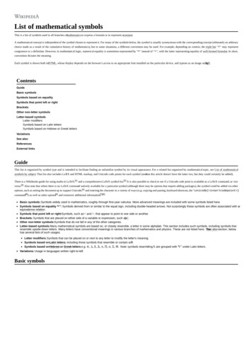
Locating the Dish AntennaUse the Dish Pointing Angles starting on page 11 to find the azimuth, elevation, and skew angles using theZIP code of your location. Write the angles in the space provided below.Elevation:Azimuth:Skew:Using these azimuth and elevation angles, find a mounting location for the satellite dish where it can bepointed towards the satellites located at these angles. Use a compass and the azimuth angle to find thedirection along the horizon that the dish should be pointed. Then use the elevation angle to find out howhigh the satellites are in the sky from your location. Make sure nothing blocks the line of sight between thedish and the satellites. Make sure this line of sight will not be blocked by future growth of nearby trees orother foliage. Also make sure your mounting location provides sufficient clearance to rotate the reflector asneeded to point toward the satellites.Assembling and Mounting the DishFollow these instructions to assemble the satellite dish, mount it, and point it in the direction of thesatellites.Using the azimuth and elevation angles, find a location for the satellite dish where it can bepointed towards the satellites located at these angles. Make sure nothing blocks the line of sightbetween the dish and the satellites.Mount the mast to a solid surface so that the dish antenna cannot move or be bumped out ofalignment. Keep in mind that physical and environmental conditions can block your satellitedish’s ability to receive a clear satellite signal. Never mount to a tree or a public utility pole.Install struts at this time, using the instructions that came with your struts.Align the top part of the mast so that it is absolutely vertical. If the top part of the mast is offvertical by only a few degrees, it will be difficult or maybe even impossible for you to find thesatellites. Take at least two readings with a level, on the upper mast, that are 90 degrees apartfrom one another (see Figure 1).Loosen the skew bolts and set the skew byrotating the dish mounting bracket to alignthe mark with the required angle on the skewscale which you wrote above. Tighten theskew bolts securely. See Table 1 for therequired torque values. After the skew isset, do not try to fine-tune the skew anglewhen aiming the dish.Note: You will need to loosen the elevationbolts and elevation rod locking nuts to accessthe skew bolts.SkewBolts(bottombolt notvisible)Figure 2. Skew PlatePage 3
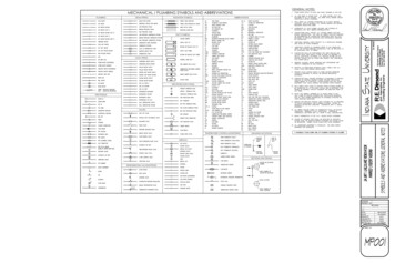
Assemble the satellite dish as shown in Figure 1, except do not attach the LNBF at this time.The LNBF Arm has a specific orientation, indicated by the labeling Top and To LNBF. Whenattaching the DISH 1000.4 LNBF Bracket to the LNBF Arm, be sure that the small posts on thebracket fit into the holes on the LNBF Arm (see Figure 3).Note: The DISH 1000.2 LNBF Bracket is not compatible with the DISH 1000.4 or the DISHPro Plus 1000.4 LNBF.Figure 3. Bracket posts fitting into LNBF arm (bolt holes removed for clarity)Set the elevation by loosening the elevation bolts and elevation rod locking nuts, and then tiltingthe dish mounting bracket to align the edge with the required angle on the elevation scale.Tighten both nuts on the elevation rod to hold the elevation, but do not tighten the side elevationbolts at this time.Elevation RodElevation RodLocking NutsAzimuth PlateFigure 4. Setting the Rough Elevation AngleSlide the dish assembly down onto the mast. Make sure the azimuth plate rests on top of themast. Turn the dish assembly so that it points in the general direction of the satellites, using theazimuth angle you wrote on page 3. You may need to loosen the two front bolts slightly tomount the dish assembly.Note: The DISH 1000.4 mast has a gripping feature that helps prevent movement of the dishantenna when fully installed. This gripping feature may give a slightly rough feel wheninstalling the dish onto the mast or when adjusting the azimuth angle.Page 4
Installing the ReceiversUse the steps below while referring to Figure 1.Run RG-6 coaxial cables from the DISH 1000.4 antenna to the receiver location(s) using thefollowing cable requirements. Grounding, other devices, and in-home cabling must also meetthese requirements. RG-6 coaxial cable rated for at least 950 to 2150 MHz must be used in this installation. Donot use existing cables such as RG-59 as it may cause signal loss. Also, be sure that anyoutdoor connections are made using weatherproof F-connectors rated for 2150 MHz orgreater. The length of the RG-6 cable from any receiver and farthest dish connected in the systemmust not be longer than 200 feet for DISH Pro or DISH Pro Plus receivers. The cable length between the DISH Pro Plus 1000.4 LNBF and a connected compatibleLNBF must be 80 feet or less, for a total cable length of no more than 200 feet from theLNBF to the receiver.The cable’s center conductor must not extend past the rim of the F-connector more thanthe thickness of a nickel.Tighten all outdoor cable connections up to the torque values recommended by themanufacturer to ensure seal against moisture. Damage caused by over-tightening is notcovered by the limited warranty. Tighten all indoor coaxial cable connections to thereceiver and any other electronic components (such as TVs or DVD players) only byhand. If you use a wrench, you may over-tighten the connections and damage yourequipment.Connect a temporary cable to a peaking meter. Thread the other end of the cable through theLNBF arm and bracket. Connect the temporary cable to PORT 2 of the DPP 1000.4 LNBF andattach the LNBF to the bracket with two screws.Note: If the peaking meter does not produce at least 600 mA to power the DPP 1000.4 LNBF,connect PORT 1 of the LNBF to the SATELLITE IN port of a powered receiver.If you are peaking the dish using a previously-installed receiver, run a Check Switch test with theSATELLITE IN cable(s) disconnected before peaking the dish (see step 10 on page 8 for helprunning the Check Switch test). This clears the previous Check Switch results and allows thereceiver to detect the signal from the DPP 1000.4 LNBF. Set the receiver’s Point Dish screen tosatellite 72.7ºW and transponder 19 or 21 if peaking using this method.Peak the dish for the strongest possible signal on the 72.7 W satellite signal using the azimuthsetting you wrote on page 3. Do not adjust the skew.Note: If you cannot find the 72.7 W signal, try adjusting the elevation up or down one or twodegrees. Ensure you are peaking the dish using transponder 19 or 21. If using a peaking meter,only odd transponders will display from 72.7 W.With the peaking meter still connected, tighten the three mast bolts labeled with a T to the torquevalues listed in Table 1 on page 6. Re-confirm signal strength after tightening the bolts.Page 5
Table 1: Torque ValuesLocationTorque Value (ft-lbs unless otherwise noted)Mast-foot pivot thru bolt (ensure no mast deformation occursduring tightening3Mast-foot locking nuts12Reflector mounting bolts8Clamp locking bolts (back and front bolts)12Skew adjustment locking nuts12Elevation adjustment locking nuts12Elevation rod locking nutsHandtightAzimuth adjustment locking nuts (do not tighten azimuth cam)12LNBF Arm to skew bracket4LNBF Arm to LNBF BracketHandtightLNBF to LNBF BracketHandtightLeaving the peaking meter connected, fine-tune the elevation angle. Using a 1/2” wrench, loosenthe top elevation nut on the elevation rod to allow the dish to be moved up and down inelevation. Move the bottom elevation nut along the elevation rod to adjust the dish’s elevationangle and achieve maximum signal. After obtaining maximum signal, tighten the top elevationnut on the elevation rod, then tighten the side elevation bolts labeled with T to the recommendedtorque value.Top Elevation NutBottom ElevationNutSide Elevation BoltFigure 5. Fine Tuning the Elevation AnglePage 6
With the peaking meter still connected, fine-tune the azimuth angle. Loosen the three azimuthbolts enough so that the two azimuth plates can rotate. Using a 1/2” wrench, rotate the azimuthfine-tuning cam to adjust the azimuth angle to achieve maximum signal. After obtainingmaximum signal, tighten the three azimuth bolts labeled with a T to the recommended torquevalue. Do not torque the azimuth fine-tuning cam.Note: You can adjust the azimuth angle three degrees in either direction using the azimuth fine-tuning cam. If the azimuth angle needs to be adjusted more than three degrees, loosen the mastclamp bolts to make the adjustment.Azimuth BoltsAzimuth BoltAzimuth CamDo Not Tighten!Figure 6. Fine Tuning the Azimuth AngleRemove the temporary cable used for peaking the dish. Thread the cable(s) from the receiver(s)through the LNBF Arm and bracket. Connect these cables to PORT 1, PORT 2 and PORT 3, asapplicable.Connect a cable from DPP 1000.4 LNBF PORT 1 (or PORT 2 or PORT 3) to a DISH Pro or DISHPro Plus (dual-tuner) satellite receiver’s SATELLITE IN connection(s).Note: Only ViP-series receivers with the circled A symbol on their Contents andFeatures labels should be used in a DISH 1000.4 installation.To connect DISH Pro Plus (dual-tuner) receivers with a single cable, install aDISH Pro Plus Separator as follows:a. Connect a cable from the DPP 1000.4 LNBF output (PORT 1, PORT 2, orPORT 3) to the DISH Pro Plus Separator Input.b. Connect cables between the receiver’s SATELLITE IN 1 and SATELLITE IN 2to SATELLITE IN 1 and SATELLITE IN 2 respectively on the DISH Pro PlusSeparator.You must use a DISH Pro Plus Separator in a single-cable/dualtuner receiver installation. A splitter or other device will not work in thisconfiguration.Tighten all indoor coaxial cable connections to the receiver only by hand. If you use awrench, you may over-tighten the connections and damage your equipment.Page 7
Connect the receiver(s) to the TV(s) and display the Point Dish screen (if not shown, for mostreceivers, press MENU-6-1-1 on the remote control).From the Point Dish screen, run Check Switch. When the Check Switch procedure finishes,you should see an Installation Summary screen similar to the ones shown below. Make sure thesummary screen shows reception from the 61.5 W, 72 W, and 77 W satellites on all availablesatellite tuners. Also confirm the LNBF is correctly identified as a DPP 1k.4 (factory software onsome models may identify this LNBF as a DPP Twin or DPP Triple, which is OK).Note: The 77 W orbital location may not be broadcasting at launch. If it is not broadcasting,77 W will not display in the Installation Summary screen. On some models, you might not seesignal from 72 W or 77 W until after you take a software download and run a Check Switch insteps 12 and 13.Figure 7. Installation Summary ScreenExit the Installation Summary screen to display the Point Dish screen. Make sure the signalstrength bar is green and locked for the 61.5 W, 72 W, and 77 W satellites.Note: You might not see signal from 72 W or 77 W until after you take a software download andrun a Check Switch in steps 10 and 11.Exit the Point Dish screen and follow the on-screen instructions for taking a receiver softwaredownload. Do not disturb the receiver during the process of downloading software. If exiting thePoint Dish screen does not start the download process, turn off the receiver for at least 20minutes (on most receivers) to allow the receiver to take a software download.Run Check Switch again and confirm reception for all three satellites on all available satellitetuners. Your Installation Summary screen should be similar to the ones shown above in step 8.This identification is OK.If installing an additional receiver, follow steps 8-13. Make sure the summary screen showsreception from the 61.5 W, 72 W, and 77 W satellites. Keep in mind that a DISH Pro or DISHPro Plus receiver must remain connected and powered at all times to power the DPP 1000.4LNBF.Page 8
Connecting a Second Satellite DishAfter completing the previous sections to install the DISH 1000.4, use these instructions to add a fourthsatellite location from a second dish to the DISH 1000.4. The LNBF from the second dish must be a DISHPro Single, DISH Pro Dual, DISH Pro Dual Band, or a DISH Network bandstacked LNBF.Install and peak the second dish antenna using a peaking meter and the instructions that camewith that dish antenna. Skip any steps regarding taking a receiver software upgrade since thiswas done in the previous section of the DISH 1000.4 Installation Instructions.Run cable from the second dish antenna location to the DISH 1000.4, referring to the cablerequirements stated in step 1 on page 5.Connect the coaxial cable between the LNBF on the second dish and the LNB IN port on the DPP1000.4 LNBF. Refer to Figure 1 on page 2.From the Point Dish screen (accessed by pressing MENU-6-1-1 on most receivers), run CheckSwitch again on all connected receivers. When the Check Switch procedure finishes, youshould see a summary screen similar to the summary screen below. Make sure the summaryscreen shows reception from the 61.5 W, 72.7 W, and 77 W satellites and the fourth satellitelocation on all available satellite tuners. If not, re-peak the DISH 1000.4 or the second dish asneeded to achieve the required signal levels. Confirm the installed LNBF on the second dish iscorrectly identified.7772461.5 1181K.4 1K.4 1K.4 DBndDPP 1k.44777261.5 1181K.4 1K.4 1K.4 DBndDPP 1k.4Figure 8. Installation Summary ScreenPage 9
Connecting to a SwitchConnecting the DPP 1000.4 LNBF to a DPP44 SwitchThe DPP 1000.4 LNBF can be connected toprovide 61.5 W, 72.7 W and 77 W satellitesignals to a DISH Pro Plus 44 switch. Referto the instructions provided with the switchfor additional considerations andinstructions. Signal for a fourth satellitelocation must be provided directly from thefourth satellite location’s LNBF to the DPPswitch. The LNB IN port on the DPP 1000.4LNBF must not be connected. In thisinstallation, the DPP 1000.4 LNBF defaultsto the following settings: PORT 1—77 W PORT 2—72.7 W PORT 3—61.5 W LNB IN—Disabled when DPP 1000.4LNBF is connected to a switch. Whenconnected to a switch, any LNBFconnected to the LNB IN port must bedisconnected from the DPP 1000.4LNBF and connected directly to theswitch.77 72.7 61.5 LNB In61.5 77 72.7 AnotherDISH NetworkSatellite Location77 72.7 61.5 Figure 9. Connecting to a SwitchNote: The DPP 1000.4 LNBF is NOT compatible with DISH Pro switches or the DISH Pro Plus 33 Switchin any installation.Page 10
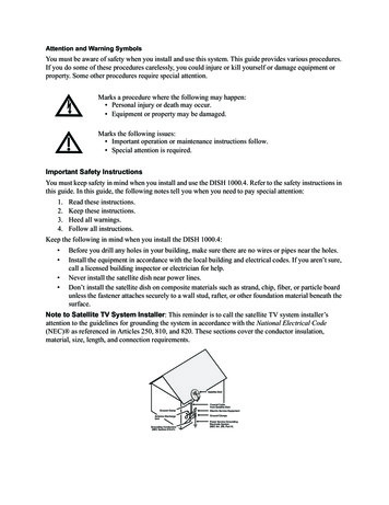
Dish Pointing AnglesUse the tables below as follows:1. Find the ZIP code for your location.2. Find the row that contains the ZIP code or the first three digits of the ZIP code. For example, thecorrect row for ZIP code 80112 is 801XX.3. Write down the number in the AZ column in the “Azimuth” blank on page 3.4. Write down the number in the EL column in the “Elevation” blank on page 3.5. Write down the number in the SK column in the “Skew” blank on page XX411989200128001303837199205Page 11
211XX4418485Page 12
400XX4416374Page 13
6175593XX2812563447XX42174
4. Assemble the dish antenna, setting the skew and elev ation angles in the process (pages 3-4, steps 4-6). 5. Mount the dish antenna on the mast and point the dish to the azimuth angle (page 4, step 7). 6. Run cables between the dish antenna and the receiver(s) , leaving a service loop around the dish mounting bracket