Transcription
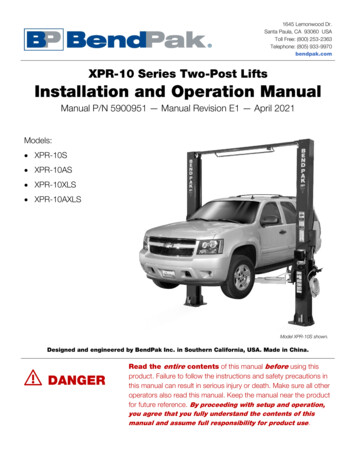
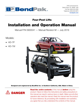
1645 Lemonwood Dr.Santa Paula, CA 93060 USAToll Free: (800) 253-2363Telephone: (805) 933-9970bendpak.comFour-Post LiftsInstallation and Operation ManualManual P/N 5900041 — Manual Revision M — July 2019Models: HD-7P HD-7WDesigned and engineered by BendPak Inc. in Southern California, USA. Made in China. DANGERRead the entire contents of this manual before using thisproduct. Failure to follow the instructions and safety precautions inthis manual can result in serious injury or death. Make sure all otheroperators also read this manual. Keep the manual near the productfor future reference. By proceeding with installation and operation,you agree that you fully understand the contents of this manual.
Manual. HD-7P and HD-7W Four-Post Lifts, Installation and Operation Manual, Manual P/N 5900041, ManualRevision M, Released July 2019.Copyright. Copyright 2019 by BendPak Inc. All rights reserved. You may make copies of this document if youagree that: you will give full attribution to BendPak Inc., you will not make changes to the content, you do not gainany rights to this content, and you will not use the copies for commercial purposes.Trademarks. BendPak and the BendPak logo are registered trademarks of BendPak Inc. All other company,product, and service names are used for identification only. All trademarks and registered trademarks mentionedin this manual are the property of their respective owners.Limitations. Every effort has been made to make sure complete and accurate instructions are included in thismanual. However, product updates, revisions, and/or changes may have occurred since this manual waspublished. BendPak reserves the right to change any information in this manual without incurring any obligation forequipment previously or subsequently sold. BendPak is not responsible for typographical errors in this manual.You can always find the latest version of the manual for your product on the BendPak website.Warranty. The BendPak warranty is more than a commitment to you: it is also a commitment to the value ofyour new product. Contact your nearest BendPak dealer or visit www.bendpak.com/support/warranty forfull warranty details. Go to bendpak.com/support/register-your-product/ and fill out the online form toregister your product (be sure to click Submit).Safety. Your product was designed and manufactured with safety in mind. However, your safety also dependson proper training and thoughtful operation. Do not install, operate, maintain, or repair the unit without reading andunderstanding this manual and the labels on the unit; do not use your Lift unless you can do so safely!Owner Responsibility. In order to maintain your product properly and to ensure everyone’s safety, it is theresponsibility of the product owner to read and follow these instructions: Follow all installation, operation, and maintenance instructions. Make sure product installation conforms to all applicable local, state, and federal codes, rules, and regulations,such as state and federal OSHA regulations and electrical codes. Read and follow all safety instructions; keep them readily available for operators. Make sure all operators are properly trained, know how to safely operate the unit, and are properly supervised. Do not operate the product until you are certain that all parts are in place and operating correctly. Carefully inspect the product on a regular basis and perform all maintenance as specified. Service and maintain the unit with approved replacement parts only. Keep instructions permanently with the productand make sure all labels are clean and visible. Only use the Lift if it can be used safely!Unit Information. Enter the Model Number, SerialNumber, and the Date of Manufacture from the labelon your unit. This information is required for part orwarranty issues.Model:Serial:Date of Manufacture:
Table of ContentsIntroduction3Operation69Shipping Information4Maintenance73Safety Considerations4Troubleshooting75Components6Wiring Diagrams77Specifications8Labels79FAQs10Parts Drawings82Installation Checklist11ALI Store90Installation12Maintenance Log91IntroductionThis manual describes the following BendPak four-post Lifts: HD-7P: Standard width, can raise Vehicles up to 7,000 pounds (3,175 kg). HD-7W: Standard and wide widths, can raise Vehicles up to 7,000 pounds (3,175 kg).Both models are ALI certified.This manual is mandatory reading for all users of the HD-7P and HD-7W, including anyone whoinstalls, uses, maintains, repairs, or wants to know more about them. DANGERUse care when installing, operating, maintaining, or repairing this equipment; failureto do so could result in property damage, product damage, injury, or (in very rarecases) death. Make sure only authorized personnel operate this equipment. Allrepairs must be performed by an authorized technician. Do not make modificationsto the unit; this voids the warranty and increases the chances of injury or propertydamage. Make sure to read and follow the instructions in this manual and on thelabels on the unit.Keep this manual on or near the equipment so that anyone who uses or services it can read it.If you are having issues, refer to the Troubleshooting section of this manual for assistance.Technical support and service is available from your dealer, on the Web at bendpak.com/support,by email at techsupport@bendpak.com, or by phone at (800) 253-2363, extension 196.You may also contact BendPak for parts replacement information at (800) 253-2363, extension191; please have the model and serial number of your unit available.HD-7P / HD-7W Four-Post Lifts3P/N 5900041 — Rev. M — July 2019
Shipping InformationYour equipment was carefully checked before shipping. Nevertheless, you should thoroughly inspectthe shipment before you sign to acknowledge that you received it.When you sign a bill of lading, it tells the carrier that the items on the invoice were received in goodcondition. To protect yourself, do not sign until after you have inspected the shipment. If any ofthe items listed on the bill of lading are missing or are damaged, do not accept the shipment until thecarrier makes a notation on the bill of lading that lists the missing and/or damaged goods.If you discover missing or damaged goods after you receive the shipment and have signed the bill oflading, notify the carrier at once and request the carrier to make an inspection. If the carrier will notmake an inspection, prepare a signed statement to the effect that you have notified the carrier (on aspecific date) and that the carrier has failed to comply with your request.It is difficult to collect for loss or damage after you have given the carrier a signed bill of lading. If thishappens to you, file a claim with the carrier promptly. Support your claim with copies of the bill oflading, freight bill, invoice, and photographs, if available. Our willingness to assist in helping youprocess your claim does not make us responsible for collection of claims or replacement of lost ordamaged materials.Safety ConsiderationsRead this entire manual carefully before installing or using the product. Do notinstall or operate the product until you are familiar with all operating instructions and warnings. Do notallow anyone else to operate it until they are familiar with all operating instructions and warnings. Keepthis manual on or near the product for future reference.Read and follow the warnings and instructions on the labels on the product. Contact BendPak at(800) 253-2363 or techsupport@bendpak.com if you need replacement labels or areplacement manual.Safety InformationThe following safety information applies to the HD-7P and the HD-7W: The product is a four-post Lift. Use it only for its intended purpose.BendPak recommends referring to the current version of the ANSI/ALI ALIS Standard SafetyRequirements for Installation and Service for information about safely installing and using your Lift.The product may only be operated by authorized, trained persons.When the Lift is in use, keep all body parts far away from it.Do not make any modifications to the Lift; this voids the warranty and increases the chances ofinjury or property damage.Make sure all operators read and understand this Installation and Operation Manual. Keep themanual near the Lift at all times.Make an inspection of the Lift before using it. Check for damaged, worn, or missing parts. Do notuse it if you find any of these issues. Instead, take it out of service, then contact an authorizedrepair facility, your dealer, or BendPak at (800) 253-2363 or techsupport@bendpak.com.BendPak recommends making a thorough inspection of the product at least once a year.Replace any damaged or severely worn parts, decals, or warning labels.HD-7P / HD-7W Four-Post Lifts4P/N 5900041 — Rev. M — July 2019
SymbolsFollowing are the symbols used in this manual: DANGER WARNING CAUTIONNOTICETipCalls attention to an immediate hazard that will result in death or severe injury.Calls attention to a hazard or unsafe practice that could result in death or severepersonal injury.Calls attention to a hazard or unsafe practice that could result in minor personalinjury, product damage, or property damage.Calls attention to a situation that, if not avoided, could result in product or propertydamage.Calls attention to information that can help you use your product better.Liability InformationBendPak Inc. assumes no liability for damages resulting from: Use of the equipment for purposes other than those described in this manual. Modifications to the equipment without prior, written permission from BendPak. Damage to the equipment from external influences. Incorrect operation of the equipment.Electrical Information DANGERAll wiring must be performed by a licensed, certified Electrician. Do not performany maintenance until main electrical power has been disconnected from the Liftand cannot be re-energized until all procedures are complete.Important electrical information: Improper electrical installation can damage the Power Unit motor, which is not covered by thewarranty.The Lift uses electrical energy; if your organization has Lockout/Tagout policies, make sure toimplement them after connecting to a power source.Use a separate circuit breaker for each Power Unit.Protect each circuit with a time delay fuse or circuit breaker:–For a 208 to 230 VAC, single phase circuit, use a 25 amp fuse.–For a 208 to 230 VAC, three phase circuit, use a 20 amp fuse.–For a 380 to 440 VAC, three phase circuit, use a 15 amp fuse.HD-7P / HD-7W Four-Post Lifts5P/N 5900041 — Rev. M — July 2019
ComponentsThe main components of your Lift include: Power Post. The Post that holds the Power Unit. The Power Post can be in either of twolocations. You can tell the Power Post from the other Posts because it has two MountingBrackets on it. Mount the Power Unit on one of the two Mounting Brackets.The other three Posts. These Posts are functionally interchangeable; their Labels are different.Power Unit. An electric/hydraulic unit that connects to an electric power source and thenprovides hydraulic power to the Hydraulic Cylinder that raises and lowers the Runways.Lifting Cables. The two Runways are lifted by .4 inch / 10 mm thick aircraft-quality steel wirerope, each of which is rated at 14,400 pounds.Powerside Runway. The Runway next to the Power Post. The Powerside Runway has LiftingCables and the Hydraulic Cylinder on its underside. You must put the Powerside Runway next tothe Power Post.Offside Runway. The other Runway. It does not have an Hydraulic Cylinder or Lifting Cablesunder it.Utility Rails. Hold the optional Rolling Jacks. Utility Rails must go on the inside of the Lift.Crosstubes. One at each end of the Lift. The Crosstubes are hollow; the Lifting Cables that raiseand lower the Runways are routed through the Crosstubes. The Crosstubes are not the same:each Crosstube has an opening (called a Window) that faces the inside (orienting the Windowscorrectly is described in the Installation section). Windows must be installed so that theyopen to the inside of the Lift. Lifting Cables go into the Crosstubes through the Windows.Ramps. One for each Runway. Use them to drive onto and off of the Runways. By definition, theRamp end of the Lift is also the Rear of the Lift.Tire Stops. Located at the Front of the Lift, Tire Stops prevent the Vehicle’s front tires from goingany further forward. Additionally, we strongly recommend chocking the Vehicle’s rear tires.Safety Locks. Once engaged, they hold the Runways in position, even if the power goes out orthere is a leak in the Hydraulic Hoses. Your Lift has 17 Safety Locks, spaced every four inches /102 mm. This lets you lock the Lift at just the right height for what you want to do. The Lift also hasa backup Slack Safety system; refer to About Safety Locks for more information. Only leaveyour Lift on the ground or engaged on a Safety Lock. Pushbutton Air Valve. Includes a Pushbutton that moves the Safety Locks away from theLadder so that they do not engage as you lower the Runways. Used only to lower the Runways.Usually located next to the Power Unit.Ladder. A piece of steel that gets installed at the back of each Post. Each Ladder has 17 holes init; part of the Safety Lock system.HD-7P / HD-7W Four-Post Lifts6P/N 5900041 — Rev. M — July 2019
Drawing not necessarily to scale. Some components not shown. Crosstube Windows for theCrosstube on the left not visible in this view.Accessories Rolling Jack(s). Optional product that raises wheels of the Vehicle on the Lift off the Runway,making it much easier to perform certain jobs while the Vehicle is still on the Lift. Refer to theRolling Jack page on the BendPak website for more information.Air Line Kit. Optional product that provides the infrastructure to get air to your Rolling Jacks,conveniently routing the air lines under the Lift’s Runways. Refer to the Air Line Kit page onthe BendPak website for more information.WSA-100 Utility Station. Optional product that adds air and electric outlets to your Lift. Referto the WSA-100 Utility Station page on the BendPak website for more information.Aluminum Decks. Optional set of two Aluminum Decks let you store items, includingmotorcycles and ATVs, on your Lift. Refer to the Aluminum Deck page on the BendPakwebsite for more information.HD-7P / HD-7W Four-Post Lifts7P/N 5900041 — Rev. M — July 2019
SpecificationsHD-7P / HD-7W Four-Post Lifts8P/N 5900041 — Rev. M — July 2019
ModelHD-7PLifting capacity7,000 lbs / 3,175 kgMaximum capacity front axle3,500 lbs / 1,750 kgMaximum capacity rear axle3,500 lbs / 1,750 kga Minimum Runway Height4.5" / 114 mmb Maximum Rise82"/ 2,083 mmc Maximum Lifting Height87" / 2,208 mmd Overall Width100.25" / 2,546 mm110.25" / 2,800 mme Outside Length174" / 4,418 mmf Overall Length200" / 5,078 mmg Height of Posts100" / 2,537 mmh Distance Between Posts90.25" / 2,292 mm100.25" / 2,546 mmi Drive-Through Clearance76.5" / 1,943 mm86.5" / 2,197 mmj Runway Width19" / 482 mmk Runway length164.5" / 4,178 mml Width Between Runways38" / 963 mm38" / 963 mm or 44.25" / 1,121 mmm Runway Centerline56.5" / 1,437 mm56.5" / 1,437 mm or 63.5" / 1,610 mmn Outside Edge of Runways75.5" / 1,919 mm75.5" / 1,919 mm or 82.5" / 2,092 mmMin. Wheelbase @ rated capacity 1115" / 2,921 mmMin. Wheelbase @ 75% capacity 1100" / 2,540 mmMin. Wheelbase @ 50% capacity185" / 2,159 mmMin. Wheelbase @ 25% capacity170" / 1,778 mmLocking Positions17, spaced every 4" / 102 mmLifting time 35 secondsMotor208-230 VAC, 60 Hz, 1 PhMax normal operating pressure208-230 VAC: 2,600 PSIPower Unit PRV setting208-230 VAC: 2,900 PSISound (when raising/lowering) 70 dBAAir supply1HD-7W3 to 25 cfm at 50 to 150 psiThe Lift supports less weight than its rated capacity when the Vehicle’s wheelbase is shorter; this isbecause the wheels are closer to the middle of the Runways, where there is less strength.Specifications subject to change without notice.HD-7P / HD-7W Four-Post Lifts9P/N 5900041 — Rev. M — July 2019
Frequently Asked QuestionsQuestion:Answer:What kinds of Vehicles can I put on my Lift?Cars, trucks, SUVs; anything that fits on the Runways, up to 7,000 lbs (3,175 kg).Q: How long does it take to raise or lower my Lift with a Vehicle on it?A: About 35 seconds. Longer if there is no weight on it.Q: Does the Lift have a Front and a Rear?A: Yes. For a four-post Lift, the end opposite the Ramps is the Front; the end with the Ramps isthe Rear.Q: Do I have to put my Power Unit in a particular location?A: Yes. Your Power Post (the Post the holds the Power Unit) must be located at either the DriverSide Front or the Passenger-Side Rear of the Lift.Q: Does the Lift have to be anchored in place?A: It is up to you. Anchoring your Lift makes it more stable, but prevents you from moving it aroundusing the optional Caster Kit. Anchoring a four-post Lift is not required.Q: How high does the ceiling have to be?A: It depends on the height of the Vehicle you are raising and how high you raise the Runways. Thegeneral rule is: 87 inches plus the height of the Vehicle should prevent any problems. However,before raising a Vehicle, BendPak strongly recommends measuring.Q: Does it matter if I drive my Vehicles in front first or back them in?A: We recommend driving your Vehicle in front first, because that makes it easier to center thewheels on the Runways. But it is up to you; the Lift works great either way. Also, remember to putthe Front wheels up against the Tire Stops and chock the Rear wheels.Q: Will the Lifting Cables really hold my Vehicle?A: Yes. Each Lifting Cable is .4 inch thick, aircraft-quality steel wire rope. Each Lifting Cable israted to hold 14, 400 pounds.Q: Do I need an Air Supply?A: Yes. An Air Supply (3 to 25 cfm at 50 to 150 psi) is required to disengage the Safety Locks whenyou want to lower the Lift. Regulate the line to a maximum pressure of 150 psi; the air lines couldburst or the Safety Locks malfunction at pressure over 150 psi.Q: How long can I leave a Vehicle on a raised Runway?A: As long as you want. Once the Lift is engaged on a Safety Lock, gravity holds it in position, so aloss of power or a leaking Hydraulic Hose does not impact it; it is going to stay where you left it.Only leave your Lift either fully lowered or engaged on Safety Locks.Q: Can I install my Lift outside?A: No. Your Lift is approved for indoor installation and use only. Outdoor installation isprohibited.Q: How many Safety Lock positions does my Lift have?A: 17, spaced every 4 inches / 102 mm.HD-7P / HD-7W Four-Post Lifts10P/N 5900041 — Rev. M — July 2019
Installation ChecklistFollowing are the steps needed to install your Lift. Perform them in the order shown. 1. Review the Safety Rules. 2. Make sure you have the necessary Tools. 3. Plan for electrical work. 4. Select an Approach. 5. Choose a Power Post Location. 6. Check the Clearances. 7. Select the Installation Location. 8. Unload and unpack the Lift Components. 9. Create Chalk Line Guides. 10. Move the Posts into position. 11. Install the Crosstubes. 12. About Safety Locks. 13. Install the Ladders and Top Caps. 14. Raise the Crosstubes. 15. Secure the Ladders. 16. Remove the Sheaves. 17. Install the Runways. 18. Install the first end of the Flex Tube. 19. Route the Lifting Cables. 20. Working with Compression Fittings and Tubing. 21. Install the Air Lines. 22. Install the Hydraulic Hose. 23. Install the Return Line. 24. Install the Power Unit. 25. Install the second end of the Flex Tube. 26. Install the Pushbutton Air Valve and connect the Air Line. 27. Connect the Return Line. 28. Connect the Hydraulic Hose. 29. Contact the Electrician. 30. Connect to a power source (Electrician required). 31. Install the Power Disconnect Switch and Thermal Disconnect Switch (Electrician required). 32. About Effective Embedment. 33. Anchor the Posts. 34. Perform final leveling. 35. Install the Accessories. 36. Lubricate the Lift. 37. Perform an Operational Test. 38. Review the Final Checklist.HD-7P / HD-7W Four-Post Lifts11P/N 5900041 — Rev. M — July 2019
InstallationThe installation process takes multiple steps. Perform them in the order listed.Read the entire Installation section before beginning the install; this gives you a betterunderstanding of the process as a whole. WARNINGOnly use the factory-supplied parts that came with your Lift. If you useparts from a different source, you void your warranty and compromise the safety ofeveryone who installs or uses the Lift. If you are missing parts, visitbendpak.com/support or call (800) 253-2363, extension 191.Being SafeWhile installing this equipment, your safety depends on proper training and thoughtful operation. WARNINGDo not install this equipment unless you have automotive Lift installation training.Always use proper lifting tools, such as a Forklift or Shop Crane, to move heavycomponents. Do not install this equipment without reading and understanding thismanual and the safety labels on the unit.Only fully trained personnel should be involved in installing this equipment. Pay attention at all times.Use appropriate tools and lifting equipment. Stay clear of moving parts.BendPak recommends referring to the current version of the ANSI/ALI ALIS Standard SafetyRequirements for Installation and Service for more information about safely installing, using, andservicing your Lift. WARNINGYou must wear appropriate protective equipment at all times during installation:gloves, steel-toe work boots, eye protection, back belts, and hearing protection.ToolsYou may need some or all of the following tools: Rotary hammer drill (or similar) ¾ inch carbide bit (conforming to ANSI B212.15) Hammer, crow bar, and two sawhorses Four-foot level and 12-foot ladder Open-end wrench set, SAE and metric Socket and ratchet set, SAE and metric Hex key wrench set Medium crescent wrench, torque wrench, pipe wrench Chalk line Medium-sized flat screwdriver and needle-nose pliers Tape measure (25 feet or above) Forklift, shop crane, or heavy-duty rolling dollyHD-7P / HD-7W Four-Post Lifts12P/N 5900041 — Rev. M — July 2019
Planning for Electrical WorkYou will need to have a licensed, certified Electrician available at some point during the installation. DANGERAll electrical work must be performed by a licensed, certified Electrician.Notify your Electrician in advance so that they come prepared with appropriate components forconnecting to the power source, a Power Disconnect Switch, and a Thermal Disconnect Switch. Referto Contacting the Electrician for more information.Your Electrician needs to: Connect the Power Unit to an electric power source. An electric power source isrequired. The Power Unit comes with a Pigtail for wiring to a power source. Have your Electricianconnect a power cord with appropriate plug to the electrical box on the Lift (for connection to apower outlet) or have them wire it directly into the electrical system at the Lift location.Note that installing the Power Unit and connecting the Power Unit to the power source areseparate procedures and are done at different times in the installation process. You do not needan Electrician to install the Power Unit, but an Electrician is required to connect the Power Unit tothe power source. Install a Power Disconnect Switch. Ensures you can quickly and completely interruptelectrical power to the Lift in the event of an electrical circuit fault, emergency situation, or whenequipment is undergoing service or maintenance. Put it within sight and reach of the Lift operator.Install a Thermal Disconnect Switch. Ensures the equipment shuts down in the event of anoverload or an overheated motor.Note:These components are not supplied with the Lift.HD-7P / HD-7W Four-Post Lifts13P/N 5900041 — Rev. M — July 2019
Selecting an Approach DirectionYou need to pick an Approach, the direction you will drive Vehicles onto your Lift, near the beginning ofthe installation process. It determines where your Ramps and Tire Stops go on the Lift and the Frontand Rear of the Lift.Selecting an Approach does not impact your Power Post location choice.In many cases, selecting an Approach is easy: the garage/shop has walls on three sides and an opendoor on the fourth side. The open door is the Approach side. If your location has an open door on bothends, pick one side to be the Approach side; install your Ramps on the Approach side and the TireStops on the other side.HD-7P / HD-7W Four-Post Lifts14P/N 5900041 — Rev. M — July 2019
Selecting a Power Post LocationYou need to pick a Power Post location now, near the beginning of the installation process, as itslocation impacts other aspects of the installation.Note:The Power Post location decision has no impact on the Approach direction or where theFront and Rear of the Lift are. It does impact other aspects of the installation, however.You have two options for Power Post location: Driver-Side Front or Passenger-Side Rear.Drawing not necessarily to scale. Not all components shown. Powerside Runway (which has theHydraulic Cylinder under it) must be installed next to the Power Post, no matter which Power Postlocation you choose.Most customers choose their Power Post location based on either preference (one option makes moresense for their shop than the other does) or easier access to the power source.HD-7P / HD-7W Four-Post Lifts15P/N 5900041 — Rev. M — July 2019
Checking ClearancesFor safety purposes, a certain amount of clear space around the Lift is required.Drawing is a top view. Not necessarily to scale. Not all components shown.HD-7P / HD-7W Four-Post Lifts16P/N 5900041 — Rev. M — July 2019
Selecting a LocationWhen selecting the location for your Lift, consider: Architectural plans. Consult the architectural plans for your desired installation location. Makesure there are no issues between what you want to do and what the plans show.Available space. Make sure there is enough space for the Lift: front, back, sides, and above.Refer to Specifications for measurements.Overhead obstructions. Check for overhead obstructions such as building supports, heaters,electrical lines, low ceilings, hanging lights, and so on. You do not want the Vehicles on theLift hitting obstructions. The Lift location should have 87 inches of height plus the height ofthe tallest Vehicle you plan on raising, if you want to make sure you do not hit anything overhead.Side and front clearances. You must leave room around the Lift. Leave at least six feet (72inches / 1.8 meters) clear on both sides and the front of the Lift, and no obstructions at all at theRear of the Lift (so you can safely drive Vehicles onto the Runways).Power. You need an appropriate power source for the Power Unit.Outdoor installations. Your Lift is approved for indoor installation and use only.Floor. Only install the Lift on a flat, Concrete floor; do not install on asphalt or any other surface.The surface must be level; do not install if the surface has more than three degrees of slope. WARNING Installing your Lift on a surface with more than three degrees of slope could lead toinjury or even death. Only install the Lift on a level floor. If your floor is not level,consider making the floor level or using a different location.Shimming. If your Concrete floor is not completely level, you can use Shims under the bases ofthe Posts, as needed, to level the Lift.To estimate your Shim requirements, use a transit level and targets to check for flatness. Use theprovided Shims as necessary.NOTICE Do not shim a Post more than half an inch using the provided Shims and Anchor Bolts.A maximum shim of 2 inches is possible by ordering optional Shim Plates. ContactBendPak at (800) 253-2363, extension 191 to order.Concrete specifications. Do not install the Lift on cracked or defective Concrete. Make surethe Concrete is at least 4.25 inches thick, 3,000 PSI, and cured for a minimum of 28 days. Do notinstall Anchor Bolts within six inches of cracks or other defects in the Concrete. CAUTIONBendPak lifts are supplied with installation instructions and Concrete anchors thatmeet the criteria set by the current version of the American National Standard“Automotive Lifts – Safety Requirements for Construction, Testing, and Validation”,ANSI/ALI ALCTV. You are responsible for any special regional structural and/orseismic anchoring requirements specified by any other agencies and/or codes suchas the Uniform Building Code (UBC) and/or International Building Code (IBC).Be sure to check your Concrete floor for the possibility of it being a post-tension slab. In thiscase, you must contact the building architect before drilling. Using ground penetrating radar mayhelp you find the tensioned steel. WARNINGHD-7P / HD-7W Four-Post LiftsCutting through a tensioned cable can result in injury or death. Do not drill into apost-tension slab unless the building architect confirms you are not going to hittensioned steel or you have located it using ground penetrating radar. If coloredsheath comes up during drilling, stop drilling immediately.17P/N 5900041 — Rev. M — July 2019
Unloading and UnpackingTry to have the components of the Lift unloaded near the installation location.Once the components are unloaded, they are your responsibility to move around. As the Lift includes anumber of heavy pieces, the closer you unload them to the installation location, the better off you are. CAUTION WARNINGHD-7P / HD-7W Four-Post LiftsSome Lift components are very heavy; if handled incorrectly, they can damagematerials like tile, sandstone, and brick. Try to handle the Lift components twice:once when delivered and once when moved into position. You must have a Forkliftor Shop Crane to move them into position. Use care when moving them.The Posts and Runways are delivered with stabilizing structures on each end. Bevery careful when removing these stabilizing structures; the Posts and Runwa
HD-7P / HD-7W Four-Post Lifts 5 P/N 5900041 — Rev. M — July 2019 Symbols Following are the symbols used in this manual: DANGER Calls attention to an immediate hazard that will result in death or severe injury. WARNING Calls attention to a hazard or unsafe practice that could result in death or severe personal injury. CAUTION Calls attention to a hazard or unsafe practice that .