Transcription
U2 Knee AiOSurgical Technique Guide
U2 MB KneeTable of ContentsDevice Description. IIU2 MB Knee System Overview.IVSurgical Overview.VISurgical ProtocolA. Distal Femoral Resection.1B. Proximal Tibial Resection.4C. Extension Gap Assessment. 11D. Femoral Sizing and Chamfer Resection. 12E. Extension and Flexion Gaps Confirmation.23F. Femoral Trial Reduction.24G. CR Pegs Preparation.25H. PS Box Preparation.26I. Proximal Tibial Preparation.29J. Onset Patellar Preparation.33K. Inset Patellar Preparation.35L. Implantation.39Appendix.44Order Information.57I
United OrthopedicU2 MB KneeDeviceDescriptionThe Mobile Bearing rotating platform knee prosthesis provides both low contact pressureon the articular surface and low shear force on the bone-implant interface.The U2 MB Knee is compatible with both U2 fixed bearing Posterior Stabilized (PS) andCruciate Retaining (CR) femoral components.MBC, Mobile Bearing Congruent Insert For use with the CR femoral component PCL can be either retained or sacrificed Central stopping mechanism designed to enhance Medial/Lateral (M/L) stability and alsoallows up to 4.5 hyper-extensionMB, Mobile Bearing InsertFor use with the PS femoral component Both ACL and PCL sacrificed Cemented MBA baseplate with stem and augment options include instruments to allowadequate management of minor or moderate tibial defects with the use of augments andthe extension stem.MBA baseplate TPS PLUS with stem option include instruments to allow further stabilitywith the use of the extension stem.INDICAIONS( MBC / MB / MBA )The device is indicated for use in total knee arthroplasty in skeletally mature patients with the following conditions:1. Rheumatoid arthritis, osteoarthritis, traumatic arthritis, polyarthritis.2. Collagen disorders, and/or avascular necrosis of the femoral condyle.3. Post-traumatic loss of joint configuration, particularly when there is patellofemoral erosion, dysfunction or prior patellectomy.4. Moderate valgus, varus, or flexion deformities.5. The salvage of previously failed surgical attempts or for a knee in which satisfactory stability in flexion cannot be obtained atthe time of surgery.This device is a single use implant and intended for cemented use only.( MBA TPS PLUS )U2 Total Knee System - Cementless Type is indicated in knee arthroplasty for reduction or relief of pain and/or improved kneefunction in skeletally mature patients with severe knee pain and disability due to rheumatoid arthritis, osteoarthritis, primaryand secondary traumatic arthritis, polyarthritis, collagen disorders, avascular necrosis of the femoral condyle or pseudogout,posttraumatic loss of joint configuration, particularly when there is patellofemoral erosion, dysfunction or prior patellectomy,moderate valgus, varus, or flexion contraction. This device may also be indicated in the salvage or previously failed surgicalattempts or for knee in which satisfactory stability in flexion cannot be obtained at the time of surgery. This device system isdesigned for cementless use.Please refer to the package inserts for important product information, including, but not limited to contraindications, warnings,precautions, and adverse effects.IIIII
United OrthopedicU2 MB KneeU2 MB Knee System OverviewFemoral ComponentPSMBCPolyethylene InsertMBIVMBAOnsetMBA TPS l BaseplateCR and CR PorousTibial BaseplateFemoral ComponentPosterior Stabilized (PS)Polyethylene InsertCruciate Retaining (CR)MBMBAOnsetMBA TPS PLUSInsetV
United OrthopedicU2 MB KneeSurgical OverviewA. Distal FemoralResectionB. Proximal TibialResectionC. Extension GapAssessmentD. Femoral Sizing and Chamfer ResectionJ. Onset PatellarPreparationG. CR Pegs PreparationF. Femoral TrialReductionI. Proximal TibialPreparationH. PS Box PreparationVIE. Extension and FlexionGaps ConfirmationL. ImplantationK. Inset PatellarPreparationVII
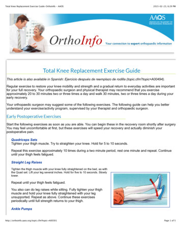
United OrthopedicU2 MB KneeA.Distal Femoral ResectionA.Distal Femoral ResectionAccess CanalSet Femoral Valgus AngleWith the ACL removed, the location of the typical femoral entry hole is deemed to beslightly medial to the center of the intercondylar notch, and approximately 5 to 7 mmanterior to the insertion of the PCL.Remove the T-Handle and slip the Femoral IM Alignment Guide through the Femoral IMRod. Use the Femoral IM Alignment Guide to set the angle of the distal femoral resectionfor either a Left or Right Knee. The guide allows up to 11 of valgus angle adjustment. Theideal angle should be determined according to pre-operative planning.Use the Step Drill to create an opening into the femoral canal. This allows fordepressurization of the canal when the Femoral IM Rod is inserted.When the alignment guide is properly engaged with the distal femur, use a Threaded Pinto secure the assemblies.Assemble the Femoral IM Rod and T-Handle, and manually insert past the isthmus of thefemoral canal.Assemble both Alignment Rod and the Extramedullary Alignment Tower to the FemoralIM Alignment Guide.The Alignment Rod can now be used todetermine the proper mechanical axis.Note: If the canal isthmus diameter is thought to betoo narrow for standard passage of the rod,advancement maybe discontinued, and anintraoperative radiograph may be employed toaccess the appropriate location of the rod.InstrumentsStep Drill1Femoral IM RodT-HandleInstrumentsFemoral IMAlignment GuideExtramedullaryAlignment towerAlignment RodQuick Pin DriverThreaded Pin30 mm/50 mm2
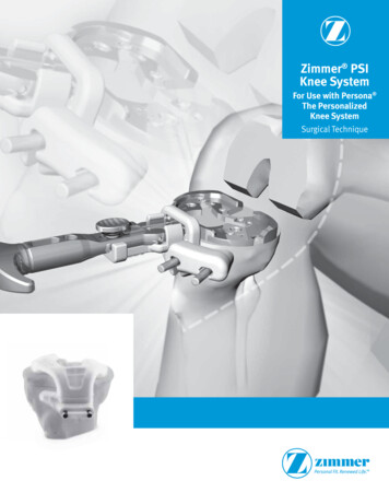
United OrthopedicU2 MB KneeA.Distal Femoral ResectionDistal Femoral ResectionAttach the Distal Femoral Cutting Guide to the Distal Femoral Alignment Guide. Drillpilot holes through the "0" pin holes on the anterior surface of the Distal Femoral CuttingGuide and insert a pair of Round Pins to secure the Cutting guide.A.Distal Femoral ResectionBefore performing the distal femur resection, additional Threaded Pins may be placed tofurther secure the resection guide. Then, use a standard .050" (1.27 mm) saw blade throughthe cutting slot to resect the distal femur.Optional tip for 1/-1 mm bone resection:The 3 mm cutting slot may be utilized by combining and shifting the Distal FemoralCutting Guide to the adjacent 2 mm or -2 mm holes to create 1- or -1 mm boneresection.For example: use the 2 mm holes for initial fixation, then shift the Distal Femoral CuttingGuide to the 0 mm holes and use 3 mm cutting slot to allow an 1 mm bone cut (bonecut from standard 9 mm to become 10 mm)Note: The U2 Knee technique is designed for a standard 9 mm distal femoral resection when theDistal Femoral Cutting Guide is set to the "0" pin hole position. The femoral componenthas a 9 mm distal femoral implant thickness.Fix with Threaded Pins If a different distal femoral resection level is required: The 2 mm or -2 mm holes may be utilized by shifting the Distal Femoral Cutting Guide.Alternatively, the 3 mm cutting slot may be used.Instruments3Distal FemoralAlignment GuideDistal FemoralCutting GuideRound PinInstrumentsQuick Pin DriverFemoral IMAlignment GuideDistal FemoralCutting GuideThreaded PinsQuick Pin Driver4
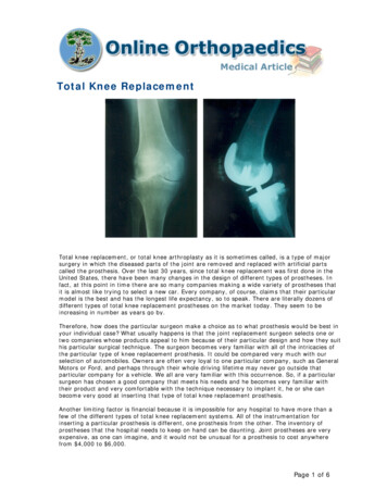
United OrthopedicU2 MB KneeB.Proximal Tibial ResectionB.Proximal Tibial ResectionThere are two options for preparing tibial platforms. One is the intramedullary alignmentmethod, and the other is the extramedullary alignment.Tibial Cutting Jig Positioning and Tibial ResectionTibial Intramedullary Alignment Method Access CanalWith the thumb screw held loosely, the Tibial Stylus may be used to establish theappropriate height position of the Tibial Cutting Jig.Position the Tibial Cutting Jig onto the Tibial IM Alignment Guide.Flex the knee joint to the maximum angle and expose the whole tibial plateau by moving itanteriorly. Use the Step Drill to create an opening into the tibial canal. The drill is inserted toa depth of approximately 100 mm into the tibial canal.After taking out the drill, it is recommended to apply an Alignment Rod into the marrowcavity several times to reduce the risk of fat embolism. Connect the T-Handle to the TibialIM Rod and insert the assembly manually into tibial canal through the narrowest pointinside. Then, remove the T-Handle. If it is difficult to insert or align the Tibial IM Rod,enlarge the pilot hole with the Step Drill again.InstrumentsStep Drill5Tibial IM RodAlignment RodInstrumentsT-HandleTibial IMAlignment GuideTibial Cutting JigTibial StylusAlignment Rod6
United OrthopedicU2 MB KneeB.Proximal Tibial ResectionTo determine the desired tibial resection level, insert the Tibial Stylus into the cutting slotand position the tip of the stylus onto the appropriate location on the tibial plateau.The Tibial Stylus allows two options to position the cutting guide at either 2 mm or 9 mmresection levels.With the Tibial Cutting Jig in the correct position, place two Round Pins into the “0” holelocations. Additional Round Pins may be used in the peripheral holes provided for additionalstability.With the Tibial Cutting Jig secured, re-assemble the T-Handle onto the Tibial IM Rodthen remove the Tibial IM Rod and Tibial IM Alignment Guide leaving the Tibial CuttingJig in position.The proximal tibial resection may be performed utilizing a 1.27 mm saw blade. Oncecompleted, the Tibial Cutting Jig and drills may be removed for subsequent trial reduction.29B.Proximal Tibial ResectionIf the Tibial Stylus tip marked 9 mm ispositioned on the high point of the tibialplateau, the bone resection will be 9 mmbelow the contact point of the stylus tip.929If the Tibial Stylus tip marked 2 mmis positioned on the low point of thetibial plateau, the bone resection will be2 mm below the contact point of thestylus tip.2Note: Prior to resection, if the surgeon wishes to increase or decreasethe tibial resection thickness, the “ 2” or “-2” hole locationsmay be utilized to re-position the Tibial Cutting Jig.InstrumentsTibial Stylus7InstrumentsTibial IMAlignment GuideTibial Cutting JigTibial StylusRound Pin8
United OrthopedicU2 MB KneeB.Proximal Tibial ResectionTibial Extramedullary Alignment MethodAttach the selected Tibial Cutting Jig to the Tibial EM Alignment Guide.B.Proximal Tibial ResectionThe resection thickness may be determined by inserting the Tibial Stylus in the resectionslot.With the knee fully flexed, position the distal portion of the Tibial EM Alignment Guidearound the ankle joint, proximal to the malleoli. Position the EM Alignment Guide rod isparallel to the anterior of the tibia from the sagittal, i.e. side, position so the proximal tibialresection will be made at 0 slope.Position the proximal portion of the Tibial EM Alignment Guide by impacting the spikes ofthe Tibial EM Alignment Guide into the central portion of the proximal tibial plateau.Fix with Round PinsInstruments9Tibial EMAlignment GuideTibial Cutting JigInstrumentsTibial StylusRound PinTibial Cutting Jig10
United OrthopedicU2 MB KneeB.Proximal Tibial ResectionB.Proximal Tibial ResectionTo determine the desired tibial resection level, insert the Tibial Stylus into the cutting slotand position the tip of the stylus onto the appropriate location on the tibial plateau.After the Tibial Cutting Jig is securely positioned, remove the Tibial EM AlignmentGuide by utilizing the Spike and Tibial EM Guide Extractor.The Tibial Stylus allows two options to position the cutting guide: 2 mm or 9 mm cuttinglevels.Use the EM Alignment Guide and Alignment Rod to recheck the alignment if necessary.The proximal tibial resection may be performed utilizing a 1.27 mm saw blade. Oncecompleted, the Tibial Cutting Jig and drills may be removed for subsequent trial reduction.92If the Tibial Stylus tip marked 9 mm ispositioned on the high point of the tibialplateau, the bone resection will be 9 mmbelow the contact point of the stylus tip.929If the Tibial Stylus tip marked 2 mmis positioned on the low point of thetibial plateau, the bone resection will be2 mm below the contact point of thestylus tip.2 Note: Prior to resection, if the surgeon wishes to increase ordecrease the tibial resection thickness, the “ 2” or “-2”hole locations may be utilized to re-position the TibialCutting Jig.InstrumentsTibial Stylus11InstrumentsTibial EMAlignment GuideTibial Cutting JigSpike and Tibial EMGuide ExtractorEM Alignment GuideAlignment Rod12
United OrthopedicU2 MB KneeC.Extension Gap AssessmentRemove any osteophytes, meniscus or other soft tissue as needed to properly completeassessment.D.Femoral Sizing andChamfer ResectionExtend the knee and insert the appropriate end of the Gap Gauge to verify the extensiongap of the knee. The Alignment Rod may be utilized to evaluate bone resection.Stylus SocketUpper Knob(Lock the Selected Size)Anterior resection slotAnterior ReferencingFixation HolesSize Panel18 mmCentral WingCentral Knob(External Rotation)Anterior ReferencingFixation HolesPosterior resection slot18 mm 9 mm Tibial Insert thickness 9 mm Femoral Component thicknessInitial Fixation HoleInstrumentsInstrumentsGap Gauge13Alignment RodBottom Knob (Fine Tune)AiO Block14
United OrthopedicU2 MB KneeD.Femoral Sizing andChamfer ResectionD.Femoral Sizing andChamfer ResectionPlacement of the AiO BlockEstablish the External RotationConfirm the bottom knob of the AiO Block is set to the zero position. Place the AiO Blockagainst the resected distal surface of the femur with the posterior feet of the block seatedon the posterior condyles. Secure the AiO Block with two 30 mm Threaded Pins throughthe initial fixation holes.Using Screwdriver, adjust the central knob to set the desired femoral component rotationangle referencing the transepicondylar axis and Whiteside's Line. The markings on thecentral knob indicate the degrees of rotation vs. the posterior condyles and can be adjustedfrom 3 to 7 in 1 increments.Parallel to Transepicondylar AxisAlign with Whiteside’s LineSecure with Threaded PinPosterior FeetOptional technique for excessive wornposterior condyles:If one posterior condyle is worn excessively,use the 1 mm or 2 mm Gap Spacer to restoredesired posterior condylar thickness.InstrumentsAiO Block15Threaded Pin30 mm/50 mmGap Spacer1 mm/2 mmInstrumentsAiO BlockScrewdriver16
United OrthopedicU2 MB KneeD.Femoral Sizing andChamfer ResectionD.Femoral Sizing andChamfer ResectionSizing the FemurDetermine the Bone Resection LevelRotate the handle of the Femoral Stylus to the unlock position. Then insert the stylus intothe slot on the top of the AiO Block. Rotate the stylus handle back to the locked position.Anterior Referencing:Secure the AiO Block by inserting a Threaded Pin in one or both of the AnteriorReferencing Fixation Holes. Use the Screwdriver to elevate the Posterior Resection Slotto an appropriate position by adjusting the Bottom Knob to match a chosen size. Note thefigures on the Bottom Knob indicate the adjustment of the posterior condylar resection levelrelative to the standard 9 mm resection.Rotate to LockFix with Threaded PinPosition the stylus tip so it is touching the lowest point on the anterior femoral cortex.Check the size panel on the front of the AiO Block. If the block is positioned to an exactsize and is in proper overall position, proceed to performing femoral resections. If the AiOBlock is not set to an exact size or is not in proper overall position, adjustments can bemade using either an anterior referencing or posterior referencing.Lowest Point of Anterior Cortex1 mm more posterior cuttingOnce the appropriate size is determined, rotatethe Upper knob to the lock position with theScrewdriver to secure the chosen size.Size Panel“0”InstrumentsAiO Block17Femoral StylusInstrumentsAiO BlockThreaded Pin30 mm/50 mmScrewdriver18
United OrthopedicU2 MB KneeD.Femoral Sizing andChamfer ResectionRemove the Femoral Stylus, then secure the anterior and posterior slots with ThreadedPins and proceed with the anterior and posterior resection.If desired, use the Resection Check Blade to confirm the resection level before boneresection.D.Femoral Sizing andChamfer ResectionPosterior Referencing:Make sure the bottom knob indicates "0", which refers to the 9 mm standard posteriorthickness in the prosthesis. Then remove the Femoral Stylus. Slide the anterior slot tomatch a proper size on the size panel.Always check the resection level with the Resection Check Blade.“0”InstrumentsAiO Block19Femoral StylusThreaded Pin30 mm/50 mmInstrumentsResection Check BladeAiO BlockResection Check Blade20
United OrthopedicU2 MB KneeD.Femoral Sizing andChamfer ResectionOnce the size is determined, rotate the upper knob with the Screwdriver to the lockposition to secure the chosen size and lock the cutting block.D.Femoral Sizing andChamfer ResectionFine TuneOccasionally, even when the proper size is chosen the desired resection level may beunsatisfactory. If this occurs, a slightly redistributed anterior and posterior bone resectionmay be considered. With the upper knob in the locked position, use the Screwdriverto rotate the bottom knob clockwise to allow for less anterior, and more posterior cut;conversely, rotate the bottom knob counterclockwise to make more anterior and a smallerposterior cut. The range of adjustment is between 2 mm and -2 mm to the standard 9 mmposterior cut.Fix the anterior and posterior slots with Threaded Pins and proceed with the anterior andposterior resection.Clockwise Rotation:Less Anterior,More Posterior ResectionCounterclockwise Rotation:More Anterior,Less Posterior ResectionInstrumentsAiO Block21ScrewdriverThreaded Pin30 mm/50 mmInstrumentsAiO BlockScrewdriver22
United OrthopedicU2 MB KneeD.Femoral Sizing andChamfer ResectionChamfer CutUse the 3.2 mm Drill to drill two reference holes for the Femoral Chamfer ResectionGuide before removing the AiO Block.D.Femoral Sizing andChamfer ResectionSecure the Femoral Chamfer Resection Guide with Threaded Pins and then completechamfer cuts.Note: The intermediate femoral sizes share thesame chamfer resection guide to integral size. E.g., Size 3.5 and Size 3 both use Size 3Femoral Chamfer Resection Guide.Fix with Threaded PinFemoral Chamfer Resection Guide can be removed by the Femoral Chamfer ResectionGuide Extractor.The Tibial EM Guide Extractor may further connect to slide out the assemblies together.Place the appropriate size Femoral Chamfer Resection Guide into the pre-drilled pin holes.Instruments3.2 mm Drill23Femoral ChamferResection GuideInstruments3.2 mm DrillFemoral ChamferResection GuideFemoral ChamferResection GuideExtractorSpike and Tibial EMGuide Extractor24
United OrthopedicU2 MB KneeE.Extension and Flexion GapsConfirmationThe extension and flexion joint gaps may be evaluated with the Gap Gauge. Select the 9 mmGap Gauge initially to assess both the extension and flexion joint gaps. If a thicker gap isrequired, combine additional Gap Gauge Blocks with different thicknesses and test again.The range of thickness is from 9 mm to 18 mm. If the assessed femoral and extension gapsare optimal, insert the femoral and tibial trials to test overall knee mobility and their relativeimplant position.Note: The Alignment Rod may be inserted through the Gap Gauge handle toassess the extramedullary alignment in both extension and flexion.F.Femoral Trial PreparationInitial Femoral Trial InsertionAssemble the selected size of CR Femoral Trial to the Femoral Driver.Introduce the femoral trial onto the prepared femur until its sitting 2-3 mm above theresected femoral surface.Strike the CR Femoral Trial onto the resected femur with the Femoral Impactor. aution:C Femoral Driver is designed to position the implant andtrial, not for final impaction. Please impact gently.18 mm18 mm 9 mm Tibial Insert thickness 9 mm Femoral Component thicknessInstrumentsGap Gauge25Alignment RodInstrumentsCR Femoral TrialFemoral DriverFemoral Impactor26
United OrthopedicU2 MB KneeG.CR Pegs PreparationDrill the fixation peg holes on the CR Femoral Trial with the Femoral Condyle Drill.H.PS Box PreparationPosition the PS Notch Cutting JigWith the reusable CR Femoral Trial in place, insert the PS Cutting Jig Drill Guide onto onefixation peg hole. Drill a pilot hole with 3.2 mm Drill through the pin hole on the drill guideand place a Round Pin through the drill guide to further position the PS Notch Cutting Jig.Remove the CR Femoral Trial and secure the PS Notch Cutting Jig with Threaded Pins.The M/L width of PS Notch Cutting Jig is the same as the M/L width of the implant.Round PinFix with Threaded PinsInstrumentsCR Femoral Trial27Femoral Condyle DrillInstrumentsCR Femoral TrialPS Cutting Jig DrillGuide3.2mm DrillRound PinPS Notch Cutting JigThreaded Pin30 mm/50 mm28
United OrthopedicU2 MB KneeH.PS Box PreparationH.PS Box PreparationPrepare PS BoxTrial ReductionAttach the PS Reamer to a drill and insert into the anterior guide slot on the PS NotchCutting Jig. Ream until fully engaged with the stopping point.Repeat for the posterior guide slot.Replace the PS Notch Cutting Jig and pins with PS Femoral Trial.Advance the PS Housing Punch intothe anterior guide slot to remove anyremaining bone or tissue. Repeat for theposterior guide slot.Advance the PS Housing Impactor intothe anterior guide slot until fully engagedwith the stopping mechanism to verify allbone and tissue is removed. Repeat forthe posterior guide slot.InstrumentsPS Notch Cutting Jig29PS ReamerPS Housing PunchInstrumentsPS Housing ImpactorPS Femoral TrialFemoral Driver30
United OrthopedicU2 MB KneeI.Proximal Tibial PreparationI.Proximal Tibial PreparationTibial Baseplate SizingCreating Space for Tibial BaseplateAttach the Tibial Baseplate Trial Handle to the Tibial Baseplate Trial and size the tibia.Alternatively, insert an Alignment Rod in the guide hole on the Tibial Baseplate TrialHandle and have the rod parallel to the tibial axis and its distal end aligned with the secondtoe as a reference for tibial baseplate position.Fix the Tibial Baseplate Trial on the tibia with 2 Head Pins. Attach the Tibial Drill Guideand drill an opening with the MBA Tibial Boss Drill until fully seated. Then remove theTibial Drill Guide and MBA Tibial Boss Drill.If the cemented or press fit extension stem is needed, please refer to the Appendix B-1or B-2.Fix with Head PinsInstrumentsTibial Baseplate Trial31Tibial BaseplateTrial HandleAlignment RodInstrumentsTibial Baseplate TrialTibial Drill GuideHead Pin*For MB Tibial Baseplate, using the MB Tibial Boss Drill in creating baseplate space.MBA Tibial Boss DrillMB Tibial Boss Drill*32
United OrthopedicU2 MB KneeI.Proximal Tibial PreparationChoose the MBA Tibial Punch that corresponds to selected Tibial Baseplate Trial andattach it to the MB Tibial Punch Handle. The corresponding sizes are marked on the side ofthe Tibial Punch.I.Proximal Tibial PreparationThe MBA Tibial Punch allows the baseplate trial to be fixed in place. Locate the CRFemoral Trial or PS Femoral Trial and choose a MBC Tibial Insert Trial or MB Tibial InsertTrial with a proper thickness and place it on the MBA Tibial Punch.Evaluate joint stability using the selected trial components. Switch to different Tibial InsertTrial thicknesses as needed to obtain optimal stability.Size #1 #2Size #3 #4Position the handle to the guide hole onthe MBA Tibial Baseplate Trial and toensure that the MBA Tibial Punch hitsprecisely and vertically into the tibial canal.Size #5 #6Detach the MBA Tibial Punch from thehandle, leaving the MBA Tibial Punch inthe canal for following trial reduction. Thenremove the pins.MBC insertMB insertMBCMBInstrumentsTibial Baseplate Trial33MB Tibial PunchHandleMBA Tibial Punch*For MB Tibial Baseplate, using the MB Tibial Punch in creating baseplate space.InstrumentsMB Tibial Punch*MBA Tibial PunchTibial Baseplate TrialMBC Insert TrialMB Insert TrialCR Femoral TrialPS Femoral Trial34
United OrthopedicU2 MB KneeJ.Onset Patellar PreparationPatella Sizing and Bone ResectionWhen the onset patellar component is chosen, assemble the Onset Patellar ResectionGuide to the Patellar Resection Clamp.Use the stylus on the bottom of Onset Patellar Resection Guide to check if the remainedpatellar thickness exceeds 10 mm.J.Onset Patellar PreparationClamp the patella tight and place the saw blade into the slot of the clamp and resect thepatella until the showing subchondral bone.Then choose the appropriate size Onset Patellar Drill Guide, and drill three peg holes withthe Onset Patellar Peg Drill completing the onset patellar preparation.Place the Onset Patellar Trial in place and confirm the restored patellar AP thickness.Onset Patellar .51010.5Diameter26293235384144Unit : mmDiameterInstrumentsPatellar Resection Clamp35Onset PatellarResection GuideInstrumentsPatellar Resection ClampOnset PatellarResection GuideOnset PatellarDrill GuideOnset Patellar Peg DrillOnset Patellar Trial36
United OrthopedicU2 MB KneeK.Inset Patellar PreparationK.Inset Patellar PreparationPatella Sizing and Bone ResectionInset Patellar Reaming Depth and Pilot HolePlace the knee in full extension and evert the patella with caution.Remove the excessive cartilage and osteophytes adjacent to the border of patella.Use the Caliper to measure the anterior-posterior dimension of the patella.Attach the appropriate size of Patellar Clamp Ring to the Patellar Resection Clamp.Use the Patellar Sizing Rings to evaluate bone coverageand select the optimal size. Once the optimal size hasbeen selected, set positioning by locating the central holeof the sizing ring with the center of the medial ridge ofthe patella. While holding the sizing ring in place, mark theouter border of the selected sizing ring.Align the Patellar Clamp Ring on the patella clamp to the previously marked position andsecure to the patella by depressing the handles on the clamp. Choose the Patellar DrillDepth Sleeve that corresponds to the selected patella size and place over the clamp ring.Insert the Patella Reamer into the Patella ring until it's tip is touching the patella.Inset Patellar Sizing Ring Diameter: 22,25,28,32 mmSurgical Tip: It is suggested to leave at least 2 mmfrom the ring to the border of the patella.InstrumentsCaliper37Patellar Sizing RingInstrumentsPatellar Clamp RingPatellarResection ClampPatellar DrillDepth SleevePatellar Reamer38
United OrthopedicU2 MB KneeK.Inset Patellar PreparationUse the Screwdriver, Hex 5 to assemble the Patellar Reamer Stopper onto the PatellarReamer with the stopper seated on the depth sleeve. This will ensure the drill depth of thereamer equals the patellar component thickness.Note: If the thickness of patella is smaller than 20 mm, it will be necessary to adjust the stopper manuallyto the desired drill depth to retainat least 8 mm patellar thickness.K.Inset Patellar PreparationRe-insert the Patellar Reamer into the Patellar Clamp Ring and ream out the proper depthof bone to create the inset bone bed.Note : A minimum bone thickness of 10 mm should be maintained. For thinner patella, theposition of the Patellar Reamer Stopper on Patella Reamer may need to be manuallyadjusted to ensure sufficient bone bed thickness.Inset Patellar ComponentThicknessRemove the Patellar Depth Sleeve and the Patella Reamer, leaving the Patellar ReamerStopper attached to the reamer.Insert the Patellar Drill Guide that corresponds to the selectedPatellar Clamp Ring. Advance the Patellar Drill (Diameter 9.45mm) and create a pilot hole for the Patellar 252832Unit:mmThen, Place the Inset Patellar Trial in place and confirm the restored patellar AP thickness.InstrumentsPatellar Reamer Stopper39Screwdriver, Hex 5Patellar Drill GuideInstrumentsPatellar DrillPatellar Clamp RingPatellar Reamer StopperPatellar ReamerPatellarResection ClampInset Patellar Trial40
United OrthopedicU2 MB KneeL.ImplantationL.ImplantationFinal Trial ReductionFemoral Component ImplantationAffix the Patellar Trial, Femoral Trial, Tibial Baseplate Trial, and Tibial Insert Trial to thecorresponding resected bony surfaces. Test for joint laxity and range of motion. Observehow the muscles and ligaments react in extension and flexion. Manage the soft tissuetension to ensure ideal joint stability and mobility. Remove all trials and clean the resectedbone surfaces.Mix and prepare bone cement in the usual fashion for the femoral component and femoralbone surface. Attach the femoral component to the Femoral Driver and press against theprepared femoral bone surface until the component is flush with the bone.Strike the Femoral Impactor to firmly seat the femoral component in place against thefemoral bone surface. Use an instrument such as a curette to remove any excess, extrudedcement. aution:C The femoral Driver is designed to position the implant and trial, not for finalimpaction. Please impact gently to avoid instrument breakage.InstrumentsCR Femoral Trial41PS Femoral TrialMBC Insert TrialMB Insert TrialInstrumentsTibial BaseplateTrial, MBInset Patellar TrialOnset Patellar TrialFemoral DriverFemoral Impactor42
United OrthopedicU2 MB KneeL.ImplantationL.ImplantationTibial Baseplate Component Implantatio
United Orthopedic U2 MB Knee. The Mobile Bearing rotating platform knee prosthesis provides both low contact pressure . on the articular surface and low shear force on the bone-implant interface. The U2 MB Knee is compatible with both U2 fixed bearing Posterior Stabilized (PS) and . Cruciate Retaining (CR) femoral components. MBC