Transcription
BlowerDoorStandardReference GuideMinneapolis BlowerDoorModel 4.1September 2009
BlowerDoor is a registered trademark of BlowerDoor GmbH.Copyrighted and published by:BlowerDoor GmbHZum Energie- und Umweltzentrum 1D-31832 Springe-Eldagsen, GermanyPhone: 49 (0)5044 975-40Fax: 49 (0)5044 975-44info@blowerdoor.dewww.blowerdoor.comAll rights reserved. This Reference Guide including all illustrations is copyrightprotected. Any use beyond the scope of use granted by copyright law withoutprior approval of the publishers is unlawful and can be prosecuted. Thisparticularly applies to copying, translating, microfilming, as well as storing andprocessing in electronic systems.
Table of ContentsTable of Contents1Equipment Safety Instructions52Installing the TECTITE Express Software for Automated BlowerDoorMeasurements7Installing the BlowerDoor Testing Equipment833.1BlowerDoor System Components . 83.2Installing the BlowerDoor Measurement System . 103.33.43.543.2.1Installing the Outside Building Pressure Tubing. 113.2.2Installing the BlowerDoor Mounting Frame and Panel . 113.2.3Installing the BlowerDoor Fan, the Flow Rings, and the Speed Controller . 153.2.4Tubing Connections to Nylon Panel and Fan . 17Installing and Connecting the DG-700 Pressure Gauge . 183.3.1The DG-700 . 183.3.2Installing the DG-700 and Connecting it to the Power Supply . 183.3.3Connecting the Speed Controller to the DG-700. 193.3.4Connecting the Tubing to the DG-700 . 203.3.5Connecting a Laptop to the DG-700 . 21Installing and Connecting the APT Pressure Gauge . 223.4.1The APT . 223.4.2Installing the APT and Connecting it to the Power Supply . 223.4.3Connecting the Speed Controller to the APT . 233.4.4Connecting the Tubing to the APT . 243.4.5Connecting a Laptop to the APT . 25Gauge Set-up for Depressurization and Pressurization Tests . 263.5.1Depressurization Measurements . 263.5.2Pressurization Measurements . 27Computer-Controlled Measurements with TECTITE Express284.1Leakage Detection with TECTITE Express at Constant Depressurization . 304.2Starting a Series of Measurements with TECTITE Express in accordance with EN13829 315Creating a Test Report with MS Excel326Leakage Detection and Automated One-Point Measurement with the DG-700(without laptop).346.1Conducting the Measurement . 346.2Notes on the DG-700 Display . 376.3Recording and Storing Baseline Building Pressure in the DG-700 . 38Minneapolis BlowerDoorSeptember 20093
Table of ContentsAppendix ASpecifications and Calibration Parameters39A.1Minneapolis BlowerDoor Specifications . 39A.2Calibration Parameters (Updated January 2007) . 40A.3Correcting the Air Density of the Flow Reading according to Manufacturer’sSpecifications . 40A.4Calibration Parameters for Flow Rings . 40Appendix BB.1Calibration, Maintenance, and Troubleshooting41DG-700 . 41Calibration . 41Battery Replacement . 41Troubleshooting / Resetting the DG-700 . 41B.2APT (Automated Performance Testing System) . 41Calibration . 41Battery and State of Charge of the APT . 41Troubleshooting the APT . 41B.3Fan42Testing the Motor Position . 42Checking the Flow Sensor . 43Cleaning the Fan . 43B.4Replacing the Speed Controller Fuse . 43B.5TECTITE Express Does Not Find the Pressure Gauge (APT / DG-700) . 44Appendix COur service offer45Adjustment and manufacturer’s calibration of your pressure gauges . 45Seminars and in-house training . 45Service at your construction site . 45Listing in the national directory of providers of BlowerDoor measurements . 45Advertising material for BlowerDoor testing teams . 45Tech Support . 45Guarantee46Object of the guarantee: BlowerDoor Standard/BlowerDoor MultipleFan. 46Process/Delivery . 46Minneapolis BlowerDoorSeptember 20094
11Equipment Safety InstructionsEquipment Safety InstructionsThe Minneapolis BlowerDoor must be connected to a power outlet installed and inspectedby qualified personnel:Power fluctuations during the test, e.g. caused by construction machinery connected at the sametime, can lead to speed variations of the BlowerDoor fan and consequently to fluctuations of thebuilding or fan pressure. This impedes exact measurement. In such cases, the BlowerDoorshould be connected directly to the power distributor at the construction site via an extension cordwith a core cross section of at least 1.5 mm² (e.g. type H07 RRF).Do not operate the BlowerDoor fan if the motor, the controller, or any of the electrical connectionsare wet.Only use approved and inspected electrical wiring and connections.Press the power plug and the appliance connector firmly into their receptacles. Failure to do socan cause overheating and possible damage.The BlowerDoor fan is a very powerful and potentially dangerous piece of equipment if notused and maintained properly:Before connecting the speed controller to the fan, be sure that the toggle switch of the controlleris at zero and that the control knob is turned completely to the left.If the fan housing, fan guards, blades, the controller, or the cords become damaged, do notoperate the fan until repairs have been made. Ensure sufficient clearance of the fan blade tipsrelative to the fan housing. Examine the motor cooling holes for excessive dust build-up. Use avacuum to remove dust or blow out the dust with compressed air.For long-term running of the BlowerDoor fan, e.g. while assessing leakage; use a smaller ringwhenever possible. This ensures good airflow over the motor even at high fan speed andprevents it from overheating Do not operate the fan for long periods of time on low speed withopen fan.If the motor gets too hot, it may experience a shut-down due to the thermal overload protection. Ifthis happens, turn off the controller so that the fan does not restart unexpectedly after it hascooled down.To prevent excess pressure build-up, start all your BlowerDoor measurements with a small ring,typically a C-ring.Keep people, pets, and objects away from the fan when it is operating:In the event of unusual noises or vibrations, stop the fan for inspection and disconnect the powerplug. If you cannot detect the source of the irregularities, contact the manufacturer/distributor.Keeping a minimum distance from the fan also contributes to higher measuring accuracy. Wheninstalling the fan make sure that you have a clearance of 1 to 2 meters around the fan, so thatthere are no obstructions to the air flow into and out of the fan. You will achieve highestmeasuring accuracy if you also maintain a side distance of at least 30cm from the fan air inlet.Minneapolis BlowerDoorSeptember 20095
1Equipment Safety InstructionsThe air blown out of the fan must flow outside unobstructed, i.e. when the air is blown intoannexes, corridors and staircases, the doors and windows of the room must be wide open.Obstruction of the air flow in front of the flow rings can influence the flow reading and lead toinaccurate results. Do not stand directly in front of the fan, but at the side of it.Install the aluminum frame securely into the door opening.At a pressure differential of 50 Pa the load on the building envelope and the BlowerDoor panel is5 kg/m². This is why the aluminum frame has to be properly fitted and installed into the dooropening to prevent it from coming loose or popping out during the test. Should the aluminumframe become loose when the test pressure increases, it will need to be re-installed. If properlyinstalled, the aluminum frame can easily resist a test pressure of 100 Pascal.Make sure that the building air barrier is protected against damage.During the test, make sure that the air barrier is protected against tearing off with wood laths. Ifthis is not the case, you must not apply more than 30 Pa of pressure differential.Always start with a small flow ring to prevent rapid, excessive pressure build-up. Caution: If youare unable to create an appropriate pressure differential with a suitable choice of ring, turn off thefan and take a walk through the building to make sure that all external doors and windows areclosed and that there are no other large openings.Necessary airsealing of the building following the BlowerDoor analysis should be startedin the attic area.If only air leaks on the ground floor or in the basement are sealed, while large leaks remain on thetop floor or attic in the roof area, thermal bouyancy will increase negative pressure. This cancause combustion backdrafting in the heating boiler and moisture or gas (radon) penetration fromthe ground.Be sure that open fires in heating boilers, fire places and woodstoves are completely outbefore starting a test.Ongoing combustion processes during a depressurization test may lead to flames being suckedout of the combustion air inlet. This is a fire hazard. In addition, combustion products could spillinto the building.Fire places in attached spaces can also be a risk if the chimney is shared and not sealed off fromthe apartment tested.If open fires cannot be extinguished, only pressurization test methods should be applied.Other than that, it is recommended to use only pressurization tests if you want to prevent fineparticles, spores and other harmful substances from building parts from being pulled into theoccupied part of the building or unit – something that could occur in a depressurization test.Minneapolis BlowerDoorSeptember 20096
2Installing the TECTITE Express Software for Automated BlowerDoor Measurements2Installing the TECTITE Express Software forAutomated BlowerDoor MeasurementsThe TECTITE Express software is a control program which allows you to control the BlowerDoorfrom a laptop and to conduct automated BlowerDoor measurements.System requirements: Windows 98 or higherSet-upLocate the set-up file TECTITE Express Language Version setup.exe on the CD supplied toyou.Start the automatic installation of the software by doubleclicking with the mouse on the file.Then follow the set-up instructions of the installation guide on the screen.If you accept all settings proposed by the installation guide, the TECTITE Express program willautomatically be saved under the path C:\Programme\Energy Conservatory. All files created byTECTITE Express will be saved under the path C:\MyFiles.Test FileOn the CD you will find a sample building test file with the file extension .bld. Open this file in theTECTITE Express and work on it. It is not necessary to set up or connect the measuringequipment to work in the file.Minneapolis BlowerDoorSeptember 20097
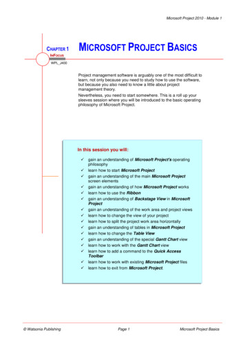
3Installing the BlowerDoor Testing Equipment3Installing the BlowerDoor Testing Equipment3.1BlowerDoor System ComponentsTransportable BlowerDoor equipment consists of the fan, thedisassembled aluminium frame in a gray bag, and the case withthe test instrumentation containing the red BlowerDoor panel, themeasuring gauge, the tube set and the speed controller, as well asthe leakage detection device of your choice (accessory).BlowerDoor fan and flow rings A to E.When inserting the rings, the letters face up to not damage thecable routing through Ring C.Aluminium frame consisting of 2 vertical frame pieces (sides),2 horizontal frame pieces (top and bottom), and 2 cross bars (thelower one is equipped with Velcro for strapping on the fan).End of external frameMinneapolis BlowerDoorSeptember 2009End of cross bar8
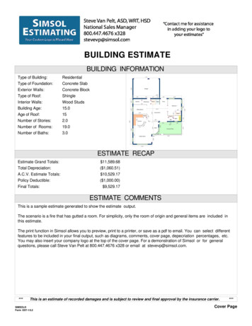
3Installing the BlowerDoor Testing EquipmentSpeed ControllerPressure Gauges DG-700 and APTFor automated measurements use the DG-700 or the APT.DG-700DG-700 pressure and flow gauge for automated and manualBlowerDoor measurementsAPT (alternative to DG-700)APT pressure and flow gauge for automated BlowerDoormeasurementsMinneapolis BlowerDoorSeptember 20099
3Installing the BlowerDoor Testing Equipment3.2Installing the BlowerDoor Measurement SystemThe BlowerDoor Measurement System is installed in an exteriordoorway of the building. It is usually fixed in a French door on theground floor (lowest floor of the tested building envelope) since themain entrance door is often not airtight and should thus beincluded in the measurement.Air flow through the fan must be unobstructed. A minimumclearance of 3m around the fan inlet and outlet is required.The BlowerDoor is controlled from the inside. The completeBlowerDoor equipment is put inside the room chosen for theinstallation.A power connection (230V) is required (power outlet or cable drumwith hook-up to the power distributor at the construction site).To prepare the building close all exterior doors and windows, openall interior doors, and apply temporary sealing if necessary.Minneapolis BlowerDoorSeptember 200910
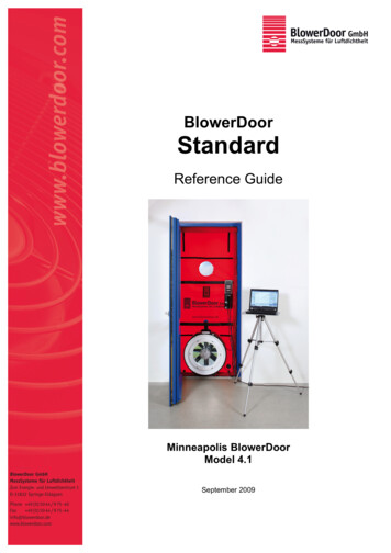
3Installing the BlowerDoor Testing Equipment3.2.1Installing the Outside Building Pressure TubingThe transparent 10m-tube for measuring the outside pressure forthe pressure differential of the building (measuring point forreference pressure) is placed at a distance of about 10m from thebuilding. At its end, slip on a T-piece to protect the tubing againstoncoming flow.Once the aluminium frame with the panel has been installed, theother end of the tubing is later connected to the panel from theoutside.3.2.2Installing the BlowerDoor Mounting Frame and PanelThe frame and the panel are installed and dismounted from the inside of the building.Before assembling the frame release all cam levers of the frameelements (see illustration).The 4 mitered external frame bars are assembled with a pushbutton catch (push down the button, join the frame elements andlet the button lock in position).Be sure that the cam levers are all on the same side of the frame.Minneapolis BlowerDoorSeptember 200911
3Installing the BlowerDoor Testing EquipmentOnce the four external elements of the aluminium frame havebeen assembled, the frame is loosely adjusted to the dimensionsof the door opening (leave about a finger’s width on all sides).Slide the frame into the door opening.Once you have released the adjustment knobs, slide the frameelements apart. To fix the respective length, retighten the knobs.Adjust the frame height by extending or shortening the sideelements of the frame. Adjust the frame width by loosening theknobs on the bottom and top elements.To leave enough space for installing the panel, do not fullyadjust the frame to the door opening. Leave about onefinger’s width of space.Unfold the BlowerDoor panel on the floor (the inside with theVelcro straps is facing up) and place the prepared aluminiumframe on top.Loosely fold the panel around the frame and secure it with theVelcro straps.Minneapolis BlowerDoorSeptember 200912
3Installing the BlowerDoor Testing EquipmentBefore inserting the frame in the door opening, run the transparentoutside building pressure tubing through the connecting patch atthe bottom of the panel.You are now ready to fit the frame and panel into the dooropening. Put one foot on the bottom frame piece and one handagainst the top frame element. Loosen the adjustment knob of oneof the side elements. Slide its pieces apart and press them into thedoor opening. Once you have fixed the height, retighten the knob.Then repeat the procedure on the other side: Loosen theadjustment knob, slide apart the frame element, and retighten theknob. Use the same method for the horizontal elements to adjustthe frame width.Finally, engage all 4 cam levers. This tightly secures the frame inthe door opening.Minneapolis BlowerDoorSeptember 200913
3Installing the BlowerDoor Testing EquipmentTo further stabilize the frame, hook the horizontal cross bars intothe slots on the side elements of the frame. Put in the cross barwith the Velcro strap (to later fix the fan) above the opening for thefan. Place the second cross bar where you can best stabilize theframe.Installing the cross bars: release adjustment knobs, slide cross barelements apart, hook ends into side frame elements, retightenadjusting knobs, engage cam lever to tighten the frame.Test frame stability and setting by rattling at the cross bar. Ifthe position of the frame changes retighten it once moreIf your power supply is located outside of the building, now run thecable from the cable drum through the opening for the fan.Minneapolis BlowerDoorSeptember 200914
3Installing the BlowerDoor Testing Equipment3.2.3Installing the BlowerDoor Fan, the Flow Rings, and the Speed ControllerFor a depressurization test fit the fan in the elastic panel collar.The flow ring must be facing towards the inside of the room. Therubber pad on the bottom of the fan casing is set on the lowerframe piece. The elastic panel collar should fit snugly around thefan casing.The Velcro strap at the lower frame crossbar vertically holds thefan in place and stabilizes it. Pull it tightly through the fan handleand secure it.View of the BlowerDoor fan with flow rings A, B, and CEach flow ring has a measuring range, in which the greatestaccuracy will be achieved. When the air flow falls below the lowerlimit of the ring, install a smaller flow ring. When the upper limit isreached, the ring must be removed to make the aperture larger.When conducting automated tests, the software will indicate anecessary change of flow rings. Otherwise, no measured value isread when the air flow falls below the lower limit. When themaximum flow ring capacity range is reached, the buildingpressure differential is not established.To change the flow rings (here the new flow ring is larger) rotatethe fastener clips to release them, and remove the flow ring. Insertflow rings with the respective letter facing up.Minneapolis BlowerDoorSeptember 200915
3Installing the BlowerDoor Testing EquipmentView of open fan and of fan with Rings A, B, and CUsing Rings D and ERing D attaches directly to the center of Ring B (remove Ring C before inserting Ring D). Theletter “D” faces upward. When using Ring D or E it is necessary to connect the red tube formeasuring air flow (fan pressure) to Ring D.Closing the fan with the fan coverTo determine the existing or baseline building pressure, pull thefan cover over the fan. During automated tests you will automatically be requested to do so.The speed controller with the DG-700 is hung onto the uppercrossbar. Before connecting the speed controller to the fan, besure that the toggle switch of the controller is in “off”-position andthat the control knob is turned completely to the left (minimum).Power is supplied to the fan via the speed controller.For the installation of the APT consult Chapter 3.4 Installing andConnecting the APT Pressure Gauge.Minneapolis BlowerDoorSeptember 200916
3Installing the BlowerDoor Testing EquipmentNow connect the speed controller to the BlowerDoor fan and thepower supply.3.2.4Tubing Connections to Nylon Panel and FanFor the pressure differential measurement of the building connectthe green tube to the connecting patch at the bottom right cornerof the panel. Outside of the building the transparent tubing for theoutside building pressure connects to the same patch.For the pressure differential measurement of the fan (to determinethe air flow) connect the red tube to the fan connection marked inred (measuring ring for Rings A, B, C, and open fan) andconnect the blue tube to the fan connection marked in blue(reference).For the pressure differential measurement of the fan (to determinethe air flow) when measuring with Rings D and E connect the redtubing to the connection on Ring D and the blue tubing with thefan connection marked in blue (reference).Minneapolis BlowerDoorSeptember 200917
3Installing the BlowerDoor Testing Equipment3.3Installing and Connecting the DG-700 Pressure Gauge3.3.1The DG-700The DG-700 is a digital pressure gauge with 2 differential pressurechannels. The measuring gauge can be used for air tightnesstesting in the following ways:The DG-700 can automatically maintain the BlowerDoor at a constant building pressure of 50PA (for leakage detection) as well as of 25 PA or 0 PA (Cruise feature).If used along with a laptop and the TECTITE Express control program, the DG-700automatically controls the BlowerDoor. Not only can you maintain a constant building pressurefor leakage detection, but you can also conduct fully automated series of measurements todetermine the air flow V50 (m³/h) at depressurization and pressurization.Alternatively, conduct manual measurements and read the differential pressures from thedisplay.At regular intervals, the measuring gauge carries out auto-zeroing of the sensors (in the operatingstate you will hear a clicking sound).Do not change the position or location of the measuring gauge during the measurement.3.3.2Installing the DG-700 and Connecting it to the Power SupplyThe DG-700 is attached above the speed controller. Secure it withthe Velcro straps at the back of the measuring gauge and on themounting board.The DG-700 is powered by 6 AA batteries (for up to about 100hours of operation). We recommend using Alkaline orrechargeable batteries with this gauge.Whenever the gauge is turned on, the battery voltage is measuredand temporarily displayed on the right display area (Channel B).When the measured battery voltage drops below 6 V the lowbattery icon BAT begins to blink in the Channel B display area. Itis time to replace the batteries.Once the batteries have fully discharged, the words LO BATappear and the DG-700 will no longer function.Before replacing the batteries turn off the gauge.Minneapolis BlowerDoorSeptember 200918
3Installing the BlowerDoor Testing Equipment3.3.3Connecting the Speed Controller to the DG-700For automated measurements connect the DG-700 to the speedcontroller of the BlowerDoor fan with the fan control cable (cablewith two jack plugs).Fan control jack at the DG-700Communication jack at the speed controllerMinneapolis BlowerDoorSeptember 200919
3Installing the BlowerDoor Testing Equipment3.3.4Connecting the Tubing to the DG-700Do not change the position or location of the measuring gauge during the measurement.Connecting the Tubing to the DG-700Channel A:Building Pressure DifferentialINPUT:open(building pressure)green tubing(outside pressure)redREF (reference):greenblueChannel B:Fan Pressure DifferentialINPUT:red tubing(fan pressure)blue tubing(fan reference pressure)REF (reference):In case of turbulence at the measuring gauge during the measurement due to unfavourableinstallation conditions (e.g. narrow corridor), additionally slip a piece of tubing on Channel A(Input). Place its end away from the flow of the fan (keep the end of this tubing inside thebuilding).Minneapolis BlowerDoorSeptember 200920
3Installing the BlowerDoor Testing Equipment3.3.5Connecting a Laptop to the DG-700To conduct automated measurements with a laptop and theTECTITE Express software connect the laptop to the DG-700 andthe DG-700 to the speed controllerDB-9 serial cable for establishing a communication link betweenthe DG-700 and the laptop.Left marking: DB-9 serial communication port for the link to thelaptop.Right marking: Fan control output jack for the fan control cablelinking to the speed controller (jack plugs).For automated measurements connect both cablesThe communication link to the laptop usually also requires a USBto DB-9 Serial adapter since more recent generations of laptopsno longer feature “real“ serial ports.Note:If the TECTITE Express software does not find the DG-700, set the number of the virtual COMport in the Device Manager to a number between 1 and 9 (TECTITE 3.6 and higher) or between 1and 4 (earlier versions of TECTITE Express).Minneapolis BlowerDoorSeptember 200921
3Installing the BlowerDoor Testing Equipment3.4Installing and Connecting the APT Pressure Gauge3.4.1The APTThe APT is a digital differential pressure gauge with 2 to 8 pressurechannels – depending on the model – and 8 analog input channels forconnecting sensors (temperature, relative humidity, etc.). For air tightnessmeasurements, the gauge can be used in the following ways:If used along with a laptop and the TECTITE Express controlsoftware, the APT controls the BlowerDoor automatically. Not only canyou maintain a constant building pressure for leakage detection, butyou can also conduct fully automated series of measurements todetermine the air flow V50 (m³/h) at depressurization andpressurization.At regular intervals, the measuring gauge carries out auto-zeroing of thepressure sensors (in the operating state you will hear a clicking sound).Do not change the position or location of the measuring gauge during the measurement.3.4.2Installing the APT and Connecting it to the Power SupplyThe APT and the speed controller can be attached to the laptop stand.The APT comes with a power supply. The gauge also includes an internalbattery with a capacity of about 4 to 6 hours of testing. The battery ischarged when the power supply is connected. The green light indicatesthat the power supply is connected to the APT.Minneapolis BlowerDoorSeptember 200922
3Installing the BlowerDoor Testing EquipmentNote:Before using the APT for the first time charge the battery for 24hours and then regularly recharge it every 2 to 3 weeks (e.g.during testing). If the APT has not been used for a while, chargethe battery overnight before beginning testing. Be sure the On/Offswitch is set to Off when not using the APT.3.4.3Connecting the Speed Controller to the APTTo conduct automated measurements with the APT connect it tothe speed controller of the fan with the Fan Control Cable (seephoto).Fan control jack at the APTCommunication jack at the speed controllerMinneapolis BlowerDoorSeptember 200923
3Installing the BlowerDoor Testing Equipment3.4.4Connecting the Tubing to the APTTurn the APT ONDo not change the position or location of the measuring gaugeduring the measurementredgreenblueConnecting the Tubing to the APTChannel P1:Building Pressure DifferentialREF (reference):green tubing(outside pressure)Channel P2:Fan Pressure DifferentialINPUT:red tubing(fan pressure)blue tubing(fan reference pressure)REF (reference):clearredgreenblueMinneapolis BlowerDoorIn case of turbulences at the measuring gauge during themeasurement due to unfavourable installation conditions (e.g.narrow corridor), additionally slip a piece of tubing on Channel P1(Input). Place its end away from the flow of the fan (keep this endof the tubing inside the building).September 200924
3Installing the BlowerDoor Testing Equipment3.4.5Connecting a Laptop to the APTTo conduct automated measurements with a laptop and theTECTITE Express software connect the laptop to the APT and theAPT to the speed controller.DB-9 serial cable for establishing a communication link betweenthe APT and the laptop.Left marking: Fan
Minneapolis BlowerDoor September 2009 6 The air blown out of the fan must flow outside unobstructed, i.e. when the air is blown into annexes, corridors and stairca