Transcription
WarmfloorsHeating MatInstallation Kit GuideSystems for all floor types,including retro-fit and low build upsUnderfloor Heating from the Ground Up.
HEATING MAT INSTALLATION GUIDEHEATING MAT INSTALLATION GUIDEINTRODUCTIONAn underfloor heating system creates a cosy andcomfortable environment on Tiled, Concretes,Timber or Carpeted floor. Our heating systemdistributes heat evenly, silently and safely.CONTENTSInstallation04-05Electrical Installation06-07Technical Information08-09Installation Instructions10-16Do’s and Don’ts17-18Installation ManualThis instruction manual contains important information regarding the safe installationand operation of heating mats These installation instructions are not intended to replaceor supersede the installation instructions provided by the manufacturers of your floorcoverings but to supplement them. Our heating mat kits are extremely strong but care mustbe taken when installing them. Please follow the step by step installation guide to ensure ahassle free installation. Ensure you read this guide carefully before commencing installationof heating mat and check that you have all the components required. The system becontrolled via an RCD protected circuit. For systems not exceeding 13 amps a fused spuror circuit beaker that has contact separation in all poles that provides full disconnectionunder Cat 3 conditions can be used. For systems larger than 13 amps a suitable protectivedevice that complies with regulations must be used. In case of any ambiguity please contactCocoon Warmfloors.23
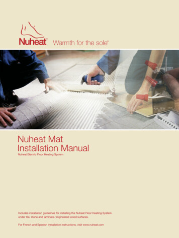
HEATING MAT INSTALLATION GUIDEHEATING MAT INSTALLATION GUIDEINSTALLATIONInstallation Notes To avoid any damage to a heating element and its terminations in timber constructionsdue to relative movement after installation use a flexible sheet of polyethylene foam. Itserves two purposes, one as a thermal insulation and secondly it absorbs the movementof wood. During installation we provide a set of 3 labels which are fixed adjacent to the distributionboard and that it has to contain the locations of the heating unitsi) Installation statement (refer to last page )ii) Drawing layoutiii) One-line diagram The installation statement will contain Date, Installer Name, Project Name, Area/LocationName. We use mainly double sided tape to fix the mat onto the floor.(POLYETHYLENE FOAM)SCAN DRAWING LAYOUT The system requires a mains voltage230/240v and must be connected by asuitably qualified person. Our heating mat elements are 12w -15wper linear meter, while wattage per metersquare is determined by spacing the cableat around 50mm to 110mm. Available in120w/sqm, 150w/sqm, 160w/sqm and200w/sqm. The power cord is a multi-core grey cablewhich is the cold tail, this carries multistrand yellow / green earth core which isconnected to the mains incoming earthfrom the supply. The second core (brown)is for live connection and the third core isneutral (N). Connect the wires dependingupon the colours required by standard ofeach countries. For larger areas (two or more mats arerequired) these can usually be connectedtogether at the thermostat or by using asmall blank fronted connection box. The system is suitable for installingon any sub-floor which is sound andsuitable for tiling ie finished floors willbe concrete, plywood or cement facedtile-backer boards. Some water resistantcomposite boards may also be suitable,but it is not recommended to tile directlyonto hardboard, MDF or standard gradechipboard as these substances absorbmoisture and subsequent swelling couldcause tiles to crack or dislodge. Pleasecheck with your installer that the sub-flooris suitable or please call our technicaladvice centre for suitability. Note : if installing on a newly finishedconcrete screed the required minimumdrying out or ‘curing’ period should befollowed before installing (this is typically1mm per day in good conditions). The electrical and electromagneticfields generated are negligible and wellwithin all recommended European andInternational guidelines. The heating mat element MUST NOT overlap or cross at any point and should beminimum 50mm apart.Contents of Heating Mat Kit.DRAWING LAYOUTONE-LINE DIAGRAM Twin-core heating element laid on glass fiber flexible mesh. Bottle/s of thermal floor primer. Disposable roller for application of primer. Digital thermostat & separate floor sensor. Warranty Certificate. Conduit for floor sensor.45
HEATING MAT INSTALLATION GUIDEHEATING MAT INSTALLATION GUIDEELECTRICAL INSTALLATIONProfessional Electrical InstallationThe faulty installation of electrical systems can cause risk of fire and electrical shock whichcan result in personal injury. Caution should always be taken to guard against such risk.Only a qualified electrician should connect the heating mats to the thermostat and or tothe electrical supply circuit.Carry out all electrical work required to install ie. chisel wallsand install back boxes for fused spurs and thermostat position. Please make sure all worksconform to the implied National Wiring Regulation. The heating units are to be suppliedthrough a Residual Current Devise (RCD) having a rated residual operating current notexcluding 30mA and upto 4.8 KW. For connecting heating units to the supply, connect all coldwire leads from the heating mats in parallel inside an electrical junction box or boxes.The thermostat used in the test is locked to a max setting of 27 C. And the tests areperformed according to floor type 2. (The results are applicable for floor type 1-5).The heating mat can also be used in floor type 4 and 5 if used with a thermostat locked to amax setting of 40 C. This test report also complies with the floor types.W/sqmFloor Types1201501602001) Concrete/wood structure (timber on top)27 C27 C27 C27 C2) Concrete/wood structure (ceramic on top)27 C27 C27 C27 CCaution3) Concrete floor (timber on top)27 C27 C27 C27 CDue to the new requirements of the Part P building Regulations, which deals with theelectrical safety in dwellings only a qualified person who is familiar with the construction andoperation of the apparatus and the hazards involved shall make the final connections to theelectricity supply and test the installation.4) Concrete floor (ceramic on top)40 C40 C40 C40 C5) Israel version Sesame gravel /sand structure(Ceramic/Marble on top)40 C27 C40 C40 CImportantAll such connections MUST be in accordance with BS7671 17th Edition Part P wiringregulations which covers design, installation, inspection testing, verification and certification.Note : When installing thermostats in bathrooms they should always be located outsidethe room and use the floor probe supplied, always check with a qualified electrician that allelectrics are in safe and suitable zones.Use a single poledisconnectionthermostat.Also use all poledisconnectionswitch next tothe thermostat.67
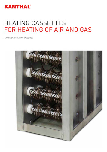
HEATING MAT INSTALLATION GUIDEHEATING MAT INSTALLATION GUIDETECHNICAL INFORMATIONTechnical tCode200W/ m2Code1.0 After unpacking them but before youinstall them. After you have installed them but beforethe floor covering (i.e. while the cable isstill exposed). For continuity and resistance value bothwires of cold lead (blue & brown) connectto multi meter and get ohms value refertable for verification. For ground testing any one wire of blueor brown and ground wire yellow/green,connect to multi meter After installation of the floor coveringbut before the thermostat is connecteda simple visual visual inspection is to becarried to ensure that there is no visibledamage to the heater, and in particularto the cable component in the heater. Asimple electrical inspection can be donewith an ohm meter to make sure the ohmresistance is as per table. Ohms resistancecan vary significantly depending on theambient temperature and variation of- 5% to 10% from the nominal value isacceptable as per IEC 60800. At this pointan insulation resistance test should nowbe carried out.OhmsEach and every Cocoon Warmfloors matis carefully tested before it is shipped fromthe factory and is packed suitably to avoiddamage during transit. However, damagedoes sometime occur in transit and westrongly recommend you test your mat priorto installation.Watt/UnitTestingProductCodeTwin core class 2 x multi strand resistance wiresfluoro polymer insulated with 0.45mm maximum (RTI).Reinforced insulationCopper shield (0.14mmx48)PVC (105) UV resistant, tested to 90ºCFlouropolymer0.5 mtr x L (L varies from 2-24 mtr)0.3 mtr & 0.2 mtr alsoType-Y attachmentIP x 21 as per IECMat Aream2Thermal ConductorCore InsulationInsulation ShieldOuter InsulationReinforcement MaterialsMesh SizeOther available Sizes areCold LeadThermostat IP Rating160W/ m2ConstructionType / Model- FHM-TWIN150W/ m2General ConstructionTwin core wire with earthVoltage230 VAC 50HzMaximum Load200w/sqmMaximum Cable Temperature80ºCApprovalsIntertek Semko EN-60335, IEC-60335-1:2001, IEC-60335-2-96:2002Power Range120w-2400wHeating mat area1.0 sqm to 12 sqmCable FlexibilityMinimum allowable cable bending radius is 25mmIP RatingIP x 7 as required by the 17th edition IEE wiring regulationsUV ResistanceUV resistant as per VDEApproved in accordance withIEC 60335-1:2010, EN60335-2-96:2008 (Under process)Ohms/unit tolerance 10/-5%120W/ m2Technical Dataxxarea9
HEATING MAT INSTALLATION GUIDEHEATING MAT INSTALLATION GUIDEINSTALLATION INSTRUCTIONStep 1Step 2Before installing, draw an installation planshowing the placement of the mats, floorsensor, and Junction-box or boxes. Theheating mats should cover at least 65% - 80%of the floor area of your room to be used asa primary heat source; the more coverage,the less time needed to heat the area.Our heating mats are available in severalconvenient sizes. Choose the combination ofheating mats that best enables you to coverthe recommended 65% - 80% of your room.Plan to use the larger heating mats as muchas possible and to use smaller mats only asgap fillers. Avoid air gaps between the heatingelement and screed. After pouring thescreed, sweep the floor throughly. Thescreed will enter the gaps in the textilemesh and there will be no air voids.Note: The mats are supplied with 16 feet (4meters) of electrical cold leads. If this is notenough, ask your electrician to extend thecold leads. At present thermal insulation boardsmade out of Polyurethane or Polystyreneare suitable because they not onlyincrease the efficiency of all Heat MatSystems but can with-stand sufficient loadfor day-today activities. The board sizevaries from 6mm to 70mm with variedthermal conductivity.Ensure that the sub-floor is solid andsuitable for tiling, free from dust anddebris. Wooden sub-floors should ideallybe reinforced to prevent flexing and thepossibility of tiles dislodging. This can bereinforced using a suitable WBP or Marineplywood or insulated tile-backer boards.Bitumen bases should be covered with asuitable backer board or a 3-5mm levelingcompound.10 Keep current orientation during laying &don’t install over irregular surface. Thermal resistance for the materialsability to resist the transfer of heat fromthe source to the ambient is measuredas a tog value. Depending upon the floorcoverings and their thermal performance,The system will support a tog value of 2.0. DO NOT install the heating mat directlyonto a bitumen base.For anhydrite screeds once primed leaveto dry (typically 1-2 hours). Once primedavoid any excess foot traffic over this area.The purpose of priming is to promotegreater adhesion and reduce the amount ofmoisture absorbed into the sub-floor.ALWAYS CHECK with tile adhesive/levelingcompound manufacturer that the primer issuitable for use with their product/s, pleasecontact our technical help centre if you arein any doubt.Step 3If using Cocoon Warmfloors tile backerboards or XPS premium insulation boards,do so in accordance with the manufacturer’sinstructions, we do advise staggering theboards in a brick bond style and making surethe boards are fixed using suitable flexibleadhesives to solid floors and or mechanicallyfixed to wooden sub-floors @ 300mm usingsuitable screws and washers.Step 4At this point we recommend referring to thetesting procedure, please take time to carrythis out as it is extremely important.11
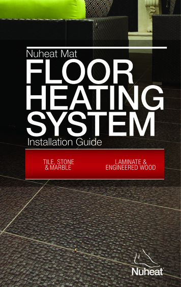
HEATING MAT INSTALLATION GUIDEHEATING MAT INSTALLATION GUIDEINSTALLATION INSTRUCTIONStep 5Split and U turn as per pictureduring mat installation.The heating element / cable MUST NOToverlap or cross at any point (the heatercables should not be spaced closer than50mm at any point to each other). Adjust thespacing if necessary to ensure all the mat isused up and the floor has an even coverage.Timber screed subfloors1 Finished floor covering, could be ceramic,stone, timber, carpet or vinyl.2 Flexible cement based tile adhesive, whentiling over thermonet, or self levellingcompound when laying a soft floor finish(vinyl, carpet or timber).3 Thermonet (Mat).4 12mm econoboard coated screwed downat 300mm centres.1234125635 Floor boards or chipboard flooring.6 Floor joists.Timber screed subfloors1 Finished floor covering, could be ceramic,stone, timber, carpet or vinyl.2 Flexible, cement based tile adhesive, whentiling over thermonet, or self levellingcompound when laying a soft floor finish(vinyl, carpet or timber). 3 Thermonet(Mat).4 Sand and cement screed.5 Polystyrene insulation.6 Concrete ground slab use of a thermalinsulation board such as econoboard willgreatly reduce heat up times and increasethe efficiency of the system this would beinstalled between points 3 & 4 stable subfloor.1212345613
HEATING MAT INSTALLATION GUIDEHEATING MAT INSTALLATION GUIDEINSTALLATION INSTRUCTIONStep 6Step 8Position the sensor in the black conduitsupplied between two runs of mat andtape into position. The sensor wire can beshortened or lengthened. If you need to cutthe sensor wire you must only cut the endcontaining the wires.Run the power leads from the start of theheating mat cable up to the thermostatposition. If the cable contains a earth braidaround the cold tail this can be unbraided byusing a screwdriver and earth wire yellow /green connected to the main earth supply- If using multiple cables route all powerleads through a conduit from the floor toa junction box and supply the junction boxfrom the thermostat. The earth from thecable can then be connected to the earthterminal in the back box, (shown here) ifusing a plastic box with no terminal then aterminal block can be used.DO NOT cut the end which contains theplastic sensor.The connections to the thermostat cannow be made. The earth from the cablecan then be connected to the earth fromthe incoming supply by using the earthterminal in the back box. If using a plasticbox with no terminal then a suitableterminal block can be used. At this point aninsulation resistance test must be carriedout by a qualified electrician. The rest of thethermostat connections can be made as perthe thermostat manufacturers guidelines.Step7Check the heating mat resistance andinsulation resistance values after laying.Check if these values are consistent with preinstall values. Record values on the warrantycertificate.14Step 9Test the heating mat resistance again usinga multi-meter. An insulation resistance testshould also be carried out to ensure thecable is free from damage.15
HEATING MAT INSTALLATION GUIDEHEATING MAT INSTALLATION GUIDEINSTALLATION INSTRUCTIONStep 10Do’sDon’tsIf possible cover the heating mat cable witha thin layer of suitable latex based levelingcompound (5-6mm). This will help protectthe cables when tiling. You may tile directlyover the cables, however extra care mustbe taken not to dislodge the cables or todamage the cables in anyway. If you areusing a suitable vinyl carpet or engineered/ laminate floor as the final covering thenwe recommend a minimum of 8mmsuitable latex levelling compound to coverthe heating mat/cables to ensure even heatdistribution. Do read through these instructionscarefully before beginning work (includingjoints) is fitted beneath the floor covering Don’t attempt to cut the heating elementat any point. Don’t allow the stress orloose heating mat Do use a multi-meter to test the cable,before, during and after covering Don’t allow excessive foot traffic over thewire before tiling. Do use a Heat Mat thermostat to controlyour system Don’t cut tiles over the heating matelement. Do test the heating mat cable beforetiling. Do be careful not to damage ordislodge the higher tog heating elementduring tiling. Do wait at least 7 days beforeturning on the system. Don’t place any product over the floorcovering that has tog value more than 2.5.You can now lay your flooring accordingto your floor manufacturer’s instructions.Please refer to adhesive manufacturer’sguidelines for drying times before turning onyour heating system, this is usually around7 days. The floor temperature should beincreased gradually by 1-2 degrees per dayover a 2 week period to reduce the risk offorce drying.Use double sided tape to fix the mat on tothe floor.Step 11Tile the floor using a flexible tile adhesiveand grout as per industry standards andmanufacturers conditions. Finally wait atleast 1 week before turning on to allowtime to dry. NOTE the heating may be slowto react at first, especially if installed on anew screed floor or in a new building. Startby setting the floor temperature at approx18 C and build up by 1 C per day until yourdesired temperature is reached. Please seeseparate instructions for connection andoperation of digital thermostat.16 Do ensure the joint between the cold tailsand heating mat element is beneath thetiles. Do ensure that the electric circuitthat supplies electricity to the underfloorheating system is equipped with a 30 mAground fault current interrupter (GFCI) orResidual Current Device (RCD). For wetareas ensure that the electric circuit thatsupplies electricity to the heating systemis equipped with a 5 mA ground faultcurrent interrupter (GFCI) or ResidualCurrent Device (RCD). Do connect all cold wire leads from theheating mats in parallel inside an electricaljunction box or boxes. Do log on to www.cocoonwarmfloors.com to ensure that you are using themost recent instructions Don’t turn on the heating mat/cable whileit is rolled up. Don’t bend the joint between the elementand cold tail Don’t supply power to the heater until thecable has been fully encased and the wettrade has been allowed to fully dry out Do not overlap heating mats. Do not fold the heating mats. Do not walk unnecessarily on the heatingmats. Do not install electrical cables or pipesunder the floor together with the heatingmats. Do not use cellulose insulation. Do not install mats when the roomtemperature is below 23ºF (-5ºC). Do not install underfloor heating matsanywhere except inside buildings. Do not install mats within 1 inch (3 cm) ofany heat conductive building part, such ascold water pipes.17
HEATING MAT INSTALLATION GUIDEHEATING MAT INSTALLATION GUIDEINSTALLATION INSTRUCTIONINSTALLATION STATEMENTDo’sDon’ts Do ensure that the total current neededfor all mats connected in parallel is notmore than 80% of the listed amperagecapacity of the electrical junction boxand its power supply line and breaker(For advice consult your recommendedinstaller / supplier). Do not install mats within 2 inches (5 cm)of one another, 4 inches (10 cm) of anywall, or 6 inches (15 cm) of a fireplace orhot water pipe.The installation statement will contain Date, Installer Name, Project Name, Area/LocationName. Each heating mat label is to be affixed on the installation statement. Do provide individual heating systemsin each room with its own electricaljunction box and control thermostat. Eachthermostat has a maximum capacity of 16amps. If the amount of amps in the roomis greater than 16 amps, use master andslave units, or add a contactor betweenthe mats and the thermostats. Do not connect any other electricalappliance on the same electric circuit orGFCI unit of the heating system. Do not use grout scrapers or utility knivesto clean grout joints or lines as sharp toolsmay damage the heating mat. Clean groutlines with a wet soft sponge or soft toolinstead. Do use insulation under the mats toreduce running costs and warm-up time.Check with your installer to determine theR‐value of the sub floor insulation layer.If there is no insulation, or if the R‐valueof the insulationlayer is lower than 0.57ft2*h* F/Btu (0.1 m2* C/W or 1 Tog), Do take full precautions to avoid anydamage during installation such asdropping sharp/heavy objects ornegligence in concrete pouring or unduestepping. Do keep the heating units at a sufficientgap away from the heat sources/fireplaces.ImportantPlease ensure that the cold tail joint (the joint between the heating cable and flexible supplylead) is fully encapsulated in adhesive or levelling compound underneath the floor coveringPlease ensure that the end joint (the joint at the end of the cable which is black) is also fullyencapsulated in tile adhesive or leveling compound. Both the cold tail joint and end jointMUST NOT be placed into a cut out of insulation or subfloor and just covered with tape, thiscan cause the cable to overheat and eventually fail!18Date:Project Reference:Opening Mat Resistance:After Installation Resistance:Resistance Before Thermostat InstallationStick First Label HereOpening Mat Resistance:After Installation Resistance:Resistance Before Thermostat InstallationStick Second Label HereOpening Mat Resistance:After Installation Resistance:Resistance Before Thermostat InstallationStick Third Label HereOpening Mat Resistance:After Installation Resistance:Resistance Before Thermostat InstallationStick Fourth Label HereMarking Plate CopyThis artwork is only a draft approved by Intertek Semko AB. For different varieties the specifications as shown in themarking plate will change accordingly.Type:FHM TwinArt No:91 160 110 15Watts/Sqm:160Watts/Unit240Ohms/Unit220 Ω, 10/-5% @ 20 deg.C230 V 50Hz (IPX7)Matt Size:0.5 x 3.0 1.5m2Max operating temperature 80 degrees CDo not restrict the thermal emission of the heated floor.Do not fix using any other materials than those recommended.Do not drill through or puncture the finished surface or use sharp tools during installation.Check for Resistance and Continuity before installation.Fill out and sign the boxes below to declare that all the information recorded on this form correlates to the l:Address:Address:Postcode:Part P hone:Signature:Customer Handover ChecklistComplete all mat tests and record results:Take photographs at each stage of the installation:Give customer original proof of purchase:Complete and sign customer handover form:Give customer a completed copy of this form:Important Safety Precautions:Three mat tests are required for the Cocoon mat.Failure to complete this form will void the warranty.Actual tested resistance may differ from those listed. Allow a tolerance of -5Ω to 10Ω of the resistance specified.19
Step 1 Before installing, draw an installation plan showing the placement of the mats, floor sensor, and Junction-box or boxes. The heating mats should cover at least 65% - 80% of the floor area of your room to be used as a primary heat source; the more coverage, the less time needed to heat the area. Our heating mats are available in several