Transcription
Liebert PPC Second Generation Power Conditioning andDistribution CabinetUser Manual—Three-Phase, 15 - 225kVA, 50 & 60Hz
The information contained in this document is subject to changewithout notice and may not be suitable for all applications. Whileevery precaution has been taken to ensure the accuracy andcompleteness of this document, Vertiv assumes no responsibilityand disclaims all liability for damages resulting from use of thisinformation or for any errors or omissions. Refer to other localpractices or building codes as applicable for the correct methods,tools, and materials to be used in performing procedures notspecifically described in this document.The products covered by this instruction manual are manufacturedand/or sold by Vertiv This document is the property of Vertiv andcontains confidential and proprietary information owned by Vertiv.Any copying, use or disclosure of it without the written permission ofVertiv is strictly prohibited.Names of companies and products are trademarks or registeredtrademarks of the respective companies. Any questions regardingusage of trademark names should be directed to the originalmanufacturer.Technical Support SiteIf you encounter any installation or operational issues with your product, check the pertinentsection of this manual to see if the issue can be resolved by following outlined procedures.Visit https://www.VertivCo.com/en-us/support/ for additional assistance.
TABLE OF CONTENTSIMPORTANT SAFETY INSTRUCTIONS . . . . . . . . . . . . . . . . . . . . . . . . . . . . . . . . . . . . . . 11.0 INSTALLATION INSTRUCTIONS . . . . . . . . . . . . . . . . . . . . . . . . . . . . . . . . . . . . . . . 21.1Unpacking and Installation . . . . . . . . . . . . . . . . . . . . . . . . . . . . . . . . . . . . . . . . . . . . . . . . . . . . . . . . . . . . . . 21.1.11.1.21.1.31.1.41.1.51.2Distribution Sidecar Mounting and Wiring . . . . . . . . . . . . . . . . . . . . . . . . . . . . . . . . . . . . . . . . . . . . . . . 91.2.11.2.21.3Unpacking and Preliminary Inspection . . . . . . . . . . . . . . . . . . . . . . . . . . . . . . . . . . . . . . . . . . . . . . . . . . . 2Handling Considerations . . . . . . . . . . . . . . . . . . . . . . . . . . . . . . . . . . . . . . . . . . . . . . . . . . . . . . . . . . . . . . . . . 2Unit Preparation . . . . . . . . . . . . . . . . . . . . . . . . . . . . . . . . . . . . . . . . . . . . . . . . . . . . . . . . . . . . . . . . . . . . . . . . . . 6Location Considerations . . . . . . . . . . . . . . . . . . . . . . . . . . . . . . . . . . . . . . . . . . . . . . . . . . . . . . . . . . . . . . . . . 6Floor Pedestal Installation . . . . . . . . . . . . . . . . . . . . . . . . . . . . . . . . . . . . . . . . . . . . . . . . . . . . . . . . . . . . . . . . 8Sidecar Mounting. . . . . . . . . . . . . . . . . . . . . . . . . . . . . . . . . . . . . . . . . . . . . . . . . . . . . . . . . . . . . . . . . . . . . . . . . 9Sidecar Electrical Connections . . . . . . . . . . . . . . . . . . . . . . . . . . . . . . . . . . . . . . . . . . . . . . . . . . . . . . . . . . . 9Power and Control Wiring. . . . . . . . . . . . . . . . . . . . . . . . . . . . . . . . . . . . . . . . . . . . . . . . . . . . . . . . . . . . . . . . 91.3.11.3.21.3.31.3.41.3.51.3.61.3.7Input Power Connections. . . . . . . . . . . . . . . . . . . . . . . . . . . . . . . . . . . . . . . . . . . . . . . . . . . . . . . . . . . . . . . . 10Junction Box Installation (If Used) . . . . . . . . . . . . . . . . . . . . . . . . . . . . . . . . . . . . . . . . . . . . . . . . . . . . . .20System Grounding. . . . . . . . . . . . . . . . . . . . . . . . . . . . . . . . . . . . . . . . . . . . . . . . . . . . . . . . . . . . . . . . . . . . . . . 22Grounding Electrode Conductor (Units With Transformer) . . . . . . . . . . . . . . . . . . . . . . . . . . . . . 22Output Power Connections. . . . . . . . . . . . . . . . . . . . . . . . . . . . . . . . . . . . . . . . . . . . . . . . . . . . . . . . . . . . . .24Control Wiring Connections . . . . . . . . . . . . . . . . . . . . . . . . . . . . . . . . . . . . . . . . . . . . . . . . . . . . . . . . . . . . .26Adapter Board . . . . . . . . . . . . . . . . . . . . . . . . . . . . . . . . . . . . . . . . . . . . . . . . . . . . . . . . . . . . . . . . . . . . . . . . . . .302.0EQUIPMENT INSPECTION AND STARTUP . . . . . . . . . . . . . . . . . . . . . . . . . . . . 312.12.2Internal Inspection . . . . . . . . . . . . . . . . . . . . . . . . . . . . . . . . . . . . . . . . . . . . . . . . . . . . . . . . . . . . . . . . . . . . . . 31Startup. . . . . . . . . . . . . . . . . . . . . . . . . . . . . . . . . . . . . . . . . . . . . . . . . . . . . . . . . . . . . . . . . . . . . . . . . . . . . . . . . . 313.0INSPECTION AND STARTUP CHECKLIST . . . . . . . . . . . . . . . . . . . . . . . . . . . . .333.13.23.33.4Inspection. . . . . . . . . . . . . . . . . . . . . . . . . . . . . . . . . . . . . . . . . . . . . . . . . . . . . . . . . . . . . . . . . . . . . . . . . . . . . . .33Startup. . . . . . . . . . . . . . . . . . . . . . . . . . . . . . . . . . . . . . . . . . . . . . . . . . . . . . . . . . . . . . . . . . . . . . . . . . . . . . . . . .34Monitoring System Check-Out . . . . . . . . . . . . . . . . . . . . . . . . . . . . . . . . . . . . . . . . . . . . . . . . . . . . . . . . .35Equipment Connection Check-Out (For Units With Distribution Cables). . . . . . . . . . . . . . .364.0OPERATING INSTRUCTIONS . . . . . . . . . . . . . . . . . . . . . . . . . . . . . . . . . . . . . . . . .374.1Startup Procedures . . . . . . . . . . . . . . . . . . . . . . . . . . . . . . . . . . . . . . . . . . . . . . . . . . . . . . . . . . . . . . . . . . . . . 374.1.14.1.24.1.34.1.4Emergency Shutdown . . . . . . . . . . . . . . . . . . . . . . . . . . . . . . . . . . . . . . . . . . . . . . . . . . . . . . . . . . . . . . . . . . . 37Normal System Shutdown . . . . . . . . . . . . . . . . . . . . . . . . . . . . . . . . . . . . . . . . . . . . . . . . . . . . . . . . . . . . . . . 37Normal System Turn ON. . . . . . . . . . . . . . . . . . . . . . . . . . . . . . . . . . . . . . . . . . . . . . . . . . . . . . . . . . . . . . . . . 37Manual Restart . . . . . . . . . . . . . . . . . . . . . . . . . . . . . . . . . . . . . . . . . . . . . . . . . . . . . . . . . . . . . . . . . . . . . . . . . . 374.2Basic Monitor Panel. . . . . . . . . . . . . . . . . . . . . . . . . . . . . . . . . . . . . . . . . . . . . . . . . . . . . . . . . . . . . . . . . . . . .384.34.44.5Power Monitor Panel. . . . . . . . . . . . . . . . . . . . . . . . . . . . . . . . . . . . . . . . . . . . . . . . . . . . . . . . . . . . . . . . . . . .39Liebert Current Plus Monitoring (If Supplied) . . . . . . . . . . . . . . . . . . . . . . . . . . . . . . . . . . . . . . . . . . 41Liebert Distribution Monitoring (If Supplied) . . . . . . . . . . . . . . . . . . . . . . . . . . . . . . . . . . . . . . . . . . .435.0MAINTENANCE . . . . . . . . . . . . . . . . . . . . . . . . . . . . . . . . . . . . . . . . . . . . . . . . . . . . . 455.15.2Corrective Maintenance . . . . . . . . . . . . . . . . . . . . . . . . . . . . . . . . . . . . . . . . . . . . . . . . . . . . . . . . . . . . . . . .45Preventive Maintenance (Inspection and Cleaning) . . . . . . . . . . . . . . . . . . . . . . . . . . . . . . . . . . . .454.2.1VertivDisplay Controls and Indicators . . . . . . . . . . . . . . . . . . . . . . . . . . . . . . . . . . . . . . . . . . . . . . . . . . . . . . . . .38 Liebert PPC User Manual i
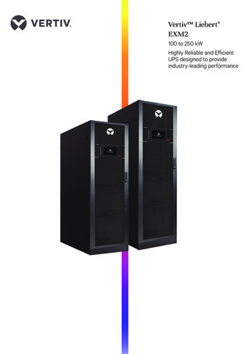
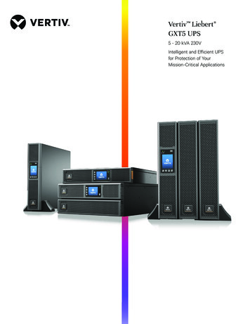
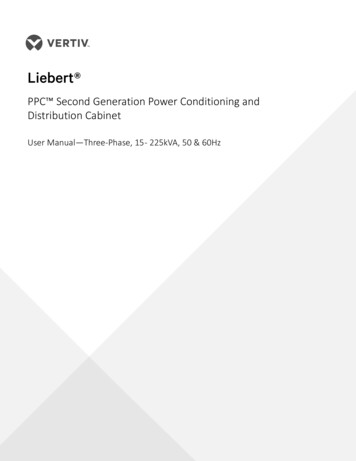
FIGURESFigure 1Figure 2Figure 3Figure 4Figure 5Figure 6Figure 7Typical cabinet and floor planning dimensions, sidecar . . . . . . . . . . . . . . . . . . . . . . . . . . . . . . 3Typical cabinet and floor planning dimension data . . . . . . . . . . . . . . . . . . . . . . . . . . . . . . . . . . 4Typical cabinet and floor planning dimension data, top exit unit. . . . . . . . . . . . . . . . . . . . . 5Recommended minimum service and ventilation clearances . . . . . . . . . . . . . . . . . . . . . . . . 7Floor pedestal details . . . . . . . . . . . . . . . . . . . . . . . . . . . . . . . . . . . . . . . . . . . . . . . . . . . . . . . . . . . . . . . . 8Electrical connection locations, sidecar unit . . . . . . . . . . . . . . . . . . . . . . . . . . . . . . . . . . . . . . . . 11Electrical connection location for 72-pole Square D or 54-pole GE panelboards, 32"cabinet,bottom entry/exit. . . . . . . . . . . . . . . . . . . . . . . . . . . . . . . . . . . . . . . . . . . . . . . . . . . . . . . . . . . . . . . . . . . . 12Figure 8 Electrical connection locations, for 54-pole Square D or 42-pole GE panelboard, 32"cabinet,bottom entry/exit. . . . . . . . . . . . . . . . . . . . . . . . . . . . . . . . . . . . . . . . . . . . . . . . . . . . . . . . . . . . . . . . . . . . 13Figure 9 Electrical connection location for 72-pole Square D or 54-pole GE panelboard, 44"cabinet,bottom entry/exit. . . . . . . . . . . . . . . . . . . . . . . . . . . . . . . . . . . . . . . . . . . . . . . . . . . . . . . . . . . . . . . . . . . . 14Figure 10 Electrical connection locations, 54-pole Square D or 42-pole GE panelboard, 44" cabinet,bottom entry/exit. . . . . . . . . . . . . . . . . . . . . . . . . . . . . . . . . . . . . . . . . . . . . . . . . . . . . . . . . . . . . . . . . . . . 15Figure 11 Electrical connection location for 54-pole Square D or 42-pole GE panelboard, 32"cabinet,top entry/exit . . . . . . . . . . . . . . . . . . . . . . . . . . . . . . . . . . . . . . . . . . . . . . . . . . . . . . . . . . . . . . . . . . . . . . . . 16Figure 12 Electrical connection location for 72-pole Square D or 54-pole GE panelboard, 44"cabinet,top entry/exit . . . . . . . . . . . . . . . . . . . . . . . . . . . . . . . . . . . . . . . . . . . . . . . . . . . . . . . . . . . . . . . . . . . . . . . 17Figure 13 Typical junction box connections . . . . . . . . . . . . . . . . . . . . . . . . . . . . . . . . . . . . . . . . . . . . . . . . . . . 21Figure 14 Typical grounding arrangements. . . . . . . . . . . . . . . . . . . . . . . . . . . . . . . . . . . . . . . . . . . . . . . . . . . .23Figure 15 Typical Liebert PPC equipment arrangement . . . . . . . . . . . . . . . . . . . . . . . . . . . . . . . . . . . . . . .25Figure 16 Simplified shutdown circuit . . . . . . . . . . . . . . . . . . . . . . . . . . . . . . . . . . . . . . . . . . . . . . . . . . . . . . . . .26Figure 17 Typical control wiring for units without monitoring . . . . . . . . . . . . . . . . . . . . . . . . . . . . . . . . . 27Figure 18 Typical control wiring for units with power monitoring. . . . . . . . . . . . . . . . . . . . . . . . . . . . . .28Figure 19 Control wiring for units without low-voltage control box. . . . . . . . . . . . . . . . . . . . . . . . . . . .29Figure 20 Liebert PPC controls and indicators . . . . . . . . . . . . . . . . . . . . . . . . . . . . . . . . . . . . . . . . . . . . . . . .38TABLESTable 1Table 2Table 3Table 4Table 5Table 6Table 7Table 8Table 9Table 10Table 11VertivHeat output . . . . . . . . . . . . . . . . . . . . . . . . . . . . . . . . . . . . . . . . . . . . . . . . . . . . . . . . . . . . . . . . . . . . . . . . . . 7Suggested minimum input wire size data . . . . . . . . . . . . . . . . . . . . . . . . . . . . . . . . . . . . . . . . . . . 18Main input circuit breaker interrupting rating . . . . . . . . . . . . . . . . . . . . . . . . . . . . . . . . . . . . . . . 19Main input junction box with transformer electrical connections . . . . . . . . . . . . . . . . . . .20Main input junction box without transformer electrical connections (5 wire) . . . . . . .20Main input (power) junction box dimensions, typical . . . . . . . . . . . . . . . . . . . . . . . . . . . . . . .20Minimum grounding electrode conductor size (AWG) . . . . . . . . . . . . . . . . . . . . . . . . . . . . . .22Panelboard main circuit breaker torque specifications. . . . . . . . . . . . . . . . . . . . . . . . . . . . . .32Branch circuit breaker torque specifications . . . . . . . . . . . . . . . . . . . . . . . . . . . . . . . . . . . . . . . .32Terminal block compression lug torque specifications. . . . . . . . . . . . . . . . . . . . . . . . . . . . . .32Torque specifications, general . . . . . . . . . . . . . . . . . . . . . . . . . . . . . . . . . . . . . . . . . . . . . . . . . . . . . .32 Liebert PPC User Manual ii
Vertiv Liebert PPC User Manual iii
Vertiv Liebert PPC User Manual iv
IMPORTANT SAFETY INSTRUCTIONSRead this entire manual before installing or operating the system.WARNINGRisk of cutting bands under tension. Can cause injury or death.The shipping bands may be under tension. Use appropriate eye, face and hand protectionto safeguard against injury from band backlash.WARNINGRisk of electric shock. Can cause injury or death.Verify that all incoming line voltage (power) and low-voltage (control) circuits arede-energized and locked out before installing cables or making connections, whether inthe junction box or in the unit.Equipment inspection and startup should be performed only by trained personnel. Lethalvoltages are present during startup procedures. Electrical safety precautions must befollowed throughout inspection and startup.Only properly trained and qualified service personnel should perform maintenance on theLiebert PPC. All voltage sources to the unit must be disconnected before inspecting orcleaning within the cabinet.Lethal voltages exist within the equipment during operation. Observe all warnings andcautions in this manual. Failure to comply may result in serious injury or death. Obtainqualified service for this equipment as instructed.The monitoring system contains a lithium battery for memory backup. Danger of explosionif battery is incorrectly replaced. Replace only with same or equivalent type. Dispose ofused batteries according to manufacturer’s instructions.WARNINGRisk of electric shock. Can cause injury or death.All power and control wiring should be installed by licensed electricians and must complywith the NEC and applicable codes.WARNINGRisk of improper handling. Can cause equipment damage, injury or death.The Liebert PPC is heavy; its weight ranges from 400lb. (182kg) to 2450lb. (1111kg) The unitshould not be loosened from the shipping pallet until after all handling by forklift or palletjack is completedELECTROMAGNETIC COMPATIBILITY—The Liebert PPC complies with the limits for a Class Adigital device, pursuant to Part 15 of FCC rules.Operation is subject to the following conditions: This device may not cause harmful interference.This device must accept any interference received, including interference that may cause undesiredoperation.Operating this device in a residential area is likely to cause harmful interference that users mustcorrect at their own expense.Vertiv Liebert PPC User Manual 1
The Liebert PPC complies with the requirements of EMC Directive 2014/30/EU and the publishedtechnical standards. Continued compliance requires installation in accordance with theseinstructions and use of accessories approved by Vertiv.Vertiv Liebert PPC User Manual 2
1.01.1INSTALLATION INSTRUCTIONSUnpacking and InstallationNOTERead the entire manual before installing and operating the system. Upon receipt of a Liebert PPC,the installer should perform the following steps to ensure a high-quality installation.1.1.1 Unpacking and Preliminary InspectionA high-quality installation begins on the receiving dock.1.2.3.Inspect for damage or signs of mishandling before unpacking the unit(s). Check the Shock-Watch indicator.If the Liebert PPC was shipped in an export crate, open the shipping crate carefully. (Use care to avoidpuncturing the container with sharp objects that would damage the contents.)Remove the packing and vapor barrier and inspect the equipment for any obvious shipping damages.NOTEThe units should not be loosened from the shipping pallet until after all handling by fork lift orpallet jack is completed. Complete internal inspection should be accomplished only afterequipment positioning and prior to electrical hookup.If any shipping damage is observed, immediately file a damage claim with the shipping agencyand forward a copy to:Vertiv Corporation1050 Dearborn DriveP.O. Box 29186Columbus, Ohio 43229 USA1.1.2 Handling ConsiderationsThe Liebert PPC is bolted to a wooden pallet to allow handling by fork lift equipment.Moving—The Liebert PPC sits on casters that allow the unit to be rolled into place after it hasbeen unbolted from the pallet.Check size and weight—Refer to the cabinet drawings furnished with the unit for size andweight information. Typical cabinet dimensions and weights are shown in Figures 1 and 2.Plan the route—The route that the unit will follow to its installation area should be planned toensure that all passages are large enough to accommodate the unit, and that the floors areadequate to support the weight. (For example: Are the doorway, elevators, ramps, etc., adequate?Are there any non-negotiable corners or offsets in the hallways?)Move with care—To prevent panel damage, Vertiv recommends removing the exterior panelsbefore moving the unit. Reconnect all panel ground wires when replacing panels.Vertiv Liebert PPC User Manual 3
Figure 1VertivTypical cabinet and floor planning dimensions, sidecar Liebert PPC User Manual 4
32"(813 mm)20"(508mm)OverallDimensionClearance of 18"(457mm) above unit isrecommended forcooling airflow .Clearance of 6"(152mm) below unit isrecommended forcooling airflow andcable exit .Shaded areas indicaterecommended clearanceof 42" (1067mm) at frontand one other side forservice access.77"(1959mm)The Liebert EXC weighs 300 lb.Cutout area forcable exit andcooling airflow .1"(25.4mm)18"(457mm)Unit Base30"(762 mm)Unit Base7"(178mm)Cabinet Dimensions10"(254 mm)18" (457 mm)30"(762mm)23-7/8"(733 mm)30" (762mm)2"(50mm)Footprint and FloorCutout Dimensions1/2"(13mm)Unit BaseOutline9/16" (14mm)Dia. HolesFloor PedestalsAvailable from 6"-19"(152mm to 483mm)6"(152mm)Optional FloorPedestals2-1/4"(57mm) Liebert PPC User Manual )Vertiv6" (152mm)3/4"(19mm)5
Figure 2Typical cabinet and floor planning dimension dataWeight, lb. (kg)CABINETFootprint and FloorCutout DimensionsUnitkVA60 Hz50 HzWithoutXfmr15650 (295)700 (318)400(182)30750 (340)800 (363)400(182)50898 (408)925 (420)400(182)751115 (507)1150 (522)400(182)1001275 (579) 1400 (635)450(204)1251450 (658)1575 (715)450(204)1501789 (813) 1900 (862)700(318)OptionalFloorPedestalsDimensions, in. (mm)Unit kVANo. ofPanelboardsABCDEF15 to 125132 (813)30 (762)18 (457)15 (381)17 (432)29 (737)150 to 225244 (1118)42 (1067)30 (762)27 (686)29 (737)41 (1041)Vertiv Liebert PPC User Manual 6
Figure 3Typical cabinet and floor planning dimension data, top exit unitUnitkVAWeight, lb. (kg)15650 (295)30750 (340)50950 (432)751165 (530)1001325 (601)1251500 (680)1501789 (813)2002110 (959)2252353 (1070)CABINET DIMENSIONSFootprint DimensionsDimensions, in. (mm)Unit kVANo. ofPanelboardsAB15-125132 (813)30 (762)150-225144 (1118)42 (1067)Vertiv Liebert PPC User Manual 7
1.1.3 Unit PreparationThe Liebert PPC may be removed from the shipping pallet and installed by customer personnel. Atypical procedure is:1.2.Set the palletized assembly in a level area, where there is enough room to roll the unit and entire cableassembly off the pallet onto the floor.Cut the shipping bands.WARNINGRisk of cutting bands under tension. Can cause injury or death.The shipping bands may be under tension. Use appropriate eye, face and hand protectionto safeguard against injury from band backlash.3.4.5.6.7.8.Remove the factory-provided ramp from its shipping position—packed in front of the unit. Place the rampadjacent to the pallet to provide a smooth path from pallet to floor.Remove side and rear panels from the module. An Allen wrench for the side panels is furnished in theinstallation packet. (Carefully disconnect panel ground wires by pulling the easy-disconnect terminals atthe unit frame.)Remove the bolts holding the unit to the shipping pallet. (Located in each of the four bottom corners.)Remove shipping blocks from under unit, then remove chocks from all casters.Roll unit off pallet onto floor.Roll unit to its installation location. For units located on a raised floor, use care when positioning unit overthe floor cutout to avoid casters falling through the cutout.NOTEBefore maneuvering the unit into its final position, read and follow all advisories in the followingparagraphs in 1.1.4 - Location Considerations.1.1.4 Location ConsiderationsThe Liebert PPC should be located within the computer room, and/or close to the load(s) which itis supplying.Equipment Location—Should employ the shortest output distribution cable runs consistentwith logical equipment arrangement and allowances for future additions.Operating Environment—Ambient temperatures of 32 F to 104 F (0 C to 40 C) with a relativehumidity of 0% to 95% (non-condensing).Bottom Clearance—Required for exit of cables/conduit and/or for cooling air flow. Thisclearance is automatically provided by a raised floor (6 in. / 150 mm minimum height). Figures 1and 2 show typical raised-floor cutout dimensions.When units are not located on a raised floor (or if the raised floor is not adequate to support theunit), optional floor pedestals may be used. (Non-raised floor applications are not CSA approved.)Units with top cable exit provisions and side vents do not require bottom clearance.Recommended Minimum Service Clearances—Shown in Figure 4. The indicated clearances atthe front and one other side or rear of the unit are required for service access by the NationalElectrical Code (NEC) (Article 110-26). Clearance above the unit is required for cooling air flow(exhaust).Heat Output—As do all electrical devices, the Liebert PPC produces heat under normaloperation. (See Table 1.) This heat output should be included when calculating theenvironmental conditions of the room.Vertiv Liebert PPC User Manual 8
Figure 4Recommended minimum service and ventilation clearances18 in. (457mm)minimum clearanceabove unit forcooling air flowSee Note 2ADDITIONAL ACCESS ONEITHER SIDE OR THE REAR OFUNIT - see Notes 1 and 2See Note 2See Note 2FRONT ACCESSREQUIRED6 in. (152 mm) minimumclearance below unit forbottom cable exitNOTES:1. Service access is required at the front, plus one other side or rear.2. Service access clearance:36 in. (914 mm) for units up to 150 volts to ground42 in. (1067 mm) for units over 150 volts to groundTable 1Heat outputFull Load Heat Output, BTU/hr (kW)kVABTU/hr (kW)151915 (0.56)303995 (0.88)504360 (1.28)756140 (1.80)1007680 (2.25)1259460 (2.77)15010,660 (3.13)20013,930 (4.08)22515,350 (4.45)Vertiv Liebert PPC User Manual 9
1.1.5 Floor Pedestal InstallationFloor pedestals are optional equipment intended to provide clearance for bottom cable entrywithout relying on a raised floor to support the unit. The pedestals are adjustable overapproximately 3-1/2 in. (89mm) to allow leveling the unit and minor adjustments in the unit’sinstalled height.NOTEFloor pedestals may be reverse-assembled for shipping. Before installation, reassemble thepedestals as shown in Figure 5. When the pedestal is properly assembled, the washer on top ofthe welded nut provides a bearing surface for the unit’s weight.1.2.3.Insert the pedestal threaded shaft into the inside corner tubing of the cabinet base as shown in Figures 1and 2.Adjust the pedestal height by turning the welded nut/shaft assembly into or out of the pedestal base asrequired.Lock the height by tightening the jam nut against the pedestal base.The pedestal may be secured to the floor by means of the four holes in the base. Locations offloor pedestals are shown in Figures 1 and 2.Vertiv Liebert PPC User Manual 10
Figure 5Floor pedestal detailsThreadedShaft3"(76mm)WasherWelded NutJam NutPedestalBase9/16" (14mm)diametermounting (57mm)1.22-1/4"(57mm)Distribution Sidecar Mounting and WiringFor Liebert PPC units with more than two panelboards, the additional panelboards are furnishedin side-mounted enclosures that are shipped separate from the main unit.1.2.1 Sidecar MountingThe additional distribution sidecar is 18 in. x 30 in. (457x762mm) and can be mounted on eitherthe left or right side of the main unit, with left side mounting recommended.Vertiv Liebert PPC User Manual 11
1.2.3.4.5.6.Provide a floor cutout for exit of output cables, as shown in Figure 1.Remove the side panel, the upper panel retainers and the lower panel hooks from the main unit.Align the distribution sidecar with the main unit and bolt the two frames together using the four bolts andhardware provided.If floor pedestals are used for the main unit, two additional floor pedestals are required for the outsidecorners of the sidecar. See Figure 1.Install the upper panel retainers and lower panel hooks on the sidecar enclosure.After electrical connections are completed, install the unit side panel on the sidecar.1.2.2 Sidecar Electrical ConnectionsFive conductors (3-phase conductors, neutral and ground) are furnished with the distributionsidecar for connection to the main unit in the field, along with an intercabinet frame groundconductor.For Liebert PPC’s with transformers, the sidecar phase conductors are connected directly to thetransformer terminals: Phase A (wire 412) to X1Phase B (wire 422) to X2Phase C (wire 432) to X3The sidecar neutral (Wire 442) and ground (Wire 452) conductors are connected to theLiebert PPC main ground busbar (see unit wiring diagram).For Liebert PPC’s without transformers, the sidecar phase and neutral conductors are connectedto the corresponding output power distribution terminal blocks inside the main unit. The sidecarground conductor is connected to the main ground busbar.For all Liebert PPC’s with VPMP monitoring, route each sidecar conductor through theappropriate current transformer (CT) in the main unit.NOTESidecar conductors must pass through the current transformers in the same direction as themain unit panelboard conductors. Use the existing main unit panelboard wiring for reference.1.3Power and Control WiringPower and control wiring should be installed by licensed electricians. All power and control wiringmust comply with the NEC and applicable local codes.Vertiv Liebert PPC User Manual 12
1.3.1 Input Power ConnectionsIf the unit is furnished with junction boxes, input power connections are made as detailed in 1.3.2 Junction Box Installation (If Used).If junction boxes are not furnished, the input power feeder is connected to the input power lugs orblocks located inside the unit. (See Figures 6, 8, and 10.)WARNINGRisk of electric shock. Can cause injury or death.Verify that all incoming line voltage (power) and low-voltage (control) circuits arede-energized and locked out before installing cables or making connections, whether inthe junction box or in the unit.To minimize disturbances caused by other loads in the building, the 3-phase power input to theunit should be supplied directly from the service entrance or other power source (a dedicatedpower feeder).The input feeder circuit should be sized in accordance with the NEC and any local building codesto assure the feeder’s ability to safely carry the system’s full load current, including losses.Input feeder conductors should be sized for no more than 2% voltage drop. If operation atundervoltage conditions for extended periods of time is desired, the input feeders must beoversized.Typical conductor size data is shown in Table 2. All connections must comply with the NEC andall other applicable codes.For units with a transformer, the main input feeder should consist of 3-phase conductors and one(safety) ground conductor (3W G).For units without a transformer, the main input feeder must consist of 3-phase conductors, oneneutral and one (safety) ground conductor (4W G).Vertiv Liebert PPC User Manual 13
Figure 6Electrical connection locations, sidecar unitNeutral ConnectionsDistribution Cables Neutral(s)connected to distributionpanelboard neutral busbarInterconnection Wiringprovided by factoryPanelboard Main Circuit BreakerFactory-WiredNOTES1. The unit bolts to the mainLiebert Precision Power Center. Seeinstallation manual for instructions.2. Site panel is taken from the Liebert PPCand installed to either the left or right sideof the unit.Distribution PanelboardGround ConnectionsDistribution Cable Ground(s)connected to distributionpanelboard ground busbarDistribution Cable Conduit ConnectionCable Tray 1-3/32" (27.8mm) holes for3/4" conduit fittings and 7/8" (22.2mm)holes for 1/2" conduit fittings provided forsecuring optional distribution cablesFRONT VIEW WITH DOOR OPENAND PANEL REMOVEDVertiv Liebert PPC User Manual PPC15010Rev. 214
Figure 7VertivElectrical connection location for 72-pole Square D or 54-pole GE panelboards, 32" cabinet, bottom Liebert PPC User Manual 15
entry/exitPPC15100Rev. 0Vertiv Liebert PPC User Manual 16
Figure 8VertivElectrical connection locations, for 54-pole Square D or 42-pole GE panelboard, 32" cabinet, Liebert PPC User Manual 17
bottom entry/exitMain Input Power ConnectionFor units without main input junction box.Busbars for 2 hole lugs (1 3/4" spacing)with 0.563" dia. holes are provided at lineside terminals of main input circuit breakerfor customer connection of 3-phase power(See Detail A)Optional Subfeed Breaker(See Detail D)Detail AInput Circuit BreakerPanelboard MainCircuit BreakerFactory-WiredNeutral ConnectionsDistribution CablesNeutral(s) connectedto distribution panelboardneutral busbar1.25"(32mm)Optional SubfeedBreaker1.74"(See Detail D)0.437" sq.(11mm)(7 Places)(44mm)1.50"(38mm)Ground ConnectionsDistribution CablesGround(
The Liebert PPC is bolted to a wooden pallet to allow handling by fork lift equipment. Moving—The Liebert PPC sits on casters that allow the unit to be rolled into place after it has been unbolted from the pallet. Check size and weight—Refer to the cabinet drawings furnished with the unit for size and weight information.