Transcription
This document was downloaded from the Penspen Integrity Virtual LibraryFor further information, contact Penspen Integrity:Penspen IntegrityUnits 7-8St. Peter's WharfNewcastle upon TyneNE6 1TZUnited KingdomTelephone: 44 (0)191 238 2200Fax: 44 (0)191 275 9786Email: integrity.ncl@penspen.comWebsite: www.penspenintegrity.com
Quarter 2, 200569High design factor pipelines:integrity issuesby Dr Phil HopkinsTechnical Director Penspen Integrity, Newcastle upon Tyne, UKTHIS PAPER considers the key design and operation parameters that affect a pipeline s operationalintegrity, and relates these parameters to pipelines with high design factors (above 0.72). Itconcludes that pipeline failure is dependent on many factors, of which design factor is one. However,in-service defects and damage have consistently been the major cause of pipeline failures in thedeveloped world. This means that the safety of our pipeline is critically dependent on how we manageits condition during its service. The paper concludes with key recommendations for pipeline designand operation at high design factors.IntroductionObjective of the paperThis paper considers some key factors thataffect pipeline integrity, and quantifies theirbenefit using failure data and research papers.These key factors are then related to highdesign factors1 ( 0.72), with the intention ofassisting operators if they are considering highdesign factor pipelines. Note that this designfactor relates to pressure containment: wallthickness calculations are also dependent onother loads, such as external loads.The paper is focused on: the pipeline, not associated facilities; new builds, but all the principles can beapplied to existing lines.It should be noted that ‘uprating’ older pipelinesto higher design factors may not be economicallyviable due to the requirements listed in thispaper, and additional requirements. This isbecause there are significant costs incurredwith upgrades at compressor stations, and itmay be impractical and too costly to hydrotestthe lines, if a hydrotest is necessary.High design factors in pipeline standards1 Design factor hoop stress/specified minimum yield strength.This paper is based on the presentation ‘Benchmarking AS2885.1: Pipeline Integrity’, by the author at the InternationalSeminar for the launch of the public comment draft of therevision of AS 2885 in Wollongong, Australia, December, 2004,hosted by APIA, and on the paper ‘High Design Factor Pipelines:Integrity Issues’, WTIA International Pipeline IntegrityConference, Wollongong, Australia. 7-9 March, 2005.Correspondence address:Penspen Integrity, Units 7-8 St Peter’s Wharf, St Peter’s Basin,Newcastle, NE6 1TZ, UKe-mail: p.hopkins@penspen.comThere are a number of pipeline codes that allowoperation of transmission pipelines at stresslevels up to, or over, 80% of the specifiedminimum yield strength; for example [1-4]: Canada - Canadian Standards AssociationZ662 USA - ASME B31.8 International - ISO 13623 UK - BS PD 8010-1Operation at stress levels up to 80% SMYS is
70The Journal of Pipeline IntegrityFactor on deathF a ct o r o nfire/explosionFactor on injuryRoad truck87.334.72.3Rail2.78.60.1Barge0.24.00.1Tanker ship4.01.23.1111Transport modePipelineTable 1 [7]. Comparison of modes of energy transportation.also being considered in the Australian StandardAS 2885-1, and these standards will be coveredin more detail below.There is significant operating experience ofhigh design factor pipelines in the USA andCanada [5]: USA: 68,000 mile-yrs (108,900 km-yrs)with design factors from 0.73 to 0.87; Canada: over 146,750 mile-yrs (234,800km-yrs) with design factors from 0.73 to0.80.the UK and the USA is driving moves to increasepipeline design factors to 0.80 [5, 6].Importance of pipelines as energy transportersOil and gas transmission pipelines are a safeform of energy transportation compared to rail,road, and sea: Table 1 compares the safety ofpipelines with these other transportation modes.For example, road trucks cause 87.3 times moredeaths than pipelines, and are 34.7 times morelikely to cause a fire or explosion. Pipelines alsohave a low impact on the environment, both interms of their presence and possible pollution:The move to higher design factors Replacing even a modest-sized pipeline,which might transport 150,000brl/d,would require 750 tanker truck loads perThe demand for oil and (in particular) gascontinues to be high, for which demand in both605040%3020100OtherE&PF acil itie sPipese lse li nes sk v-ta nNonBarge sTankersFig.1 [2]. Oil spills in marinewaters: 1990 to 1999.
Quarter 2, 200571Incidents per 6-20010.300.481997-20010.210.38Table 2 [9]. Failure data for USA and European pipelines.day [7]. That is a load delivered every twominutes around the clock. Replacing thesame pipeline with a railroad train oftank cars carrying 2,000brl each wouldrequire a 75-car train to arrive and beunloaded every day. Figure 1 [8] shows the amount of oil spilledin marine waters worldwide from 1990 to1999; the total amount was 943 milliongallons (2.9 million tons). Figure 1 showsthat pipeline spills amounted to 6% of thetotal spills. These amounts compare tothe Exxon Valdez which spilled 11 milliongallons (257,000brl); it was carrying 53million gallons.Another attraction of pipelines is that theirsafety record is improving. Table 2 [9] is asummary of pipeline failure statistics for oiland gas pipelines in the USA and Europe. It canbe seen that recent years has seen a decrease inthe number of failures, despite the pipelineinfrastructure ageing.Finally, it should be noted that operatingpipelines at higher design factors will increaseassociated failure risk slightly (see later), butthe alternative (to fulfill the demand for oil andgas) would be to use higher-risk modes oftransportation (Table 1), or additional pipelines(which have an associated risk).Maintaining safety levelsUnfortunately, pipelines still fail, and theirfailures can have tragic consequences. Recentfailures in the USA [10] have resulted in the USDepartment of Transportation issuingregulations that require pipeline integrityvalidation (through inspection, testing, andanalysis) of pipelines that run through or nearhigh-consequence areas2 (HCAs). The codewriters have produced documents to helppipeline operators meet these new regulations[11, 12].It is not only the USA that has experiencedserious pipeline failures: in August, 2004, a gaspipeline failed in Ghislenghien, Belgium with18 fatalities.Consequently, we need to continually reviewour pipeline designs and operation to improveour pipeline safety, but we must never forget2 HCAs are defined for liquid lines as populated areas,commercially-navigable waterways, and areas that are unusuallysensitive to environmental damage. For gas lines they aretypically Class 3 and 4 locations as defined in ASME B31.8 [1].
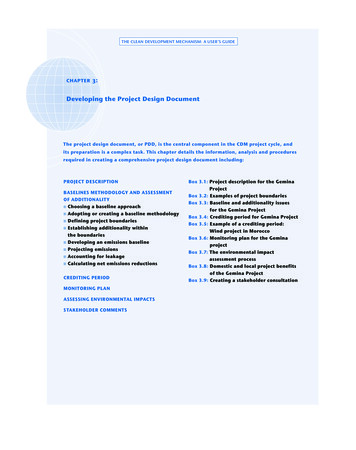
72The Journal of Pipeline IntegrityIdentify potentialpipeline impactby threatGathering, reviewing& integrating dataRisk assessmentEvaluate all threatsIntegrity assessmentIn lineinspect,hydrotest ,directassessment,or ‘other’Response to integrityassessment & mitigationFig.2 [12]. Integrity management process flow diagram from ASME B31.8S.that we are dealing with a good, efficient, andsafe mode of energy transportation.Pipeline integrity, management,and planning‘Pipeline integrity’ is ensuring a pipeline is safeand secure, and involves all aspects of apipeline’s design, inspection, management,operation, and maintenance. ‘Pipeline integritymanagement’ is the management of all theseaspects.Any management scheme must have a plan ofaction. Reference 11 (API 1160) considers anintegrity-management program as one that: identifies and analyses all events thatcould lead to failure examines likelihood and consequences ofpotential pipeline incidents examines and compares all risks provides a framework to select andimplement risk mitigation measures establishes and tracks performance, withthe goal of improvementReference 12 (ASME B31.8S) presents a simpleschematic of how a pipeline managementprogram is structured, Fig.2.We are experiencing change in the pipelinebusiness: poor-quality materials and a lack ofunderstanding of major risk meant that, 30years ago and before, we needed standards thatensured we had good-quality pipe, carefulrouteing, etc. But now we know that in-servicedefects (damage and corrosion – see next section)fail pipelines and cause casualties [13] (see nextsection). Hence, a pipeline’s ‘integrity’ isdependent on its design, operation, andmanagement, and pipeline standards need tochange to accommodate more on monitoringintegrity during a pipeline’s life.
Quarter 2, 200573Causes of pipelinefaults1 detected by inline inspection (%)Causes of pipelinefaults (%)Causes of gas loss (%)External corrosion252341External interference30191Pipe defects21545Girth welds4132Ground movement130.41923731141768239561'Other'Total incidents1 - Faults are part-wall defects with no gas loss.2 - Minor construction damage such as arc strikes or small gouges, or coating damage.3 - Small leaks from valve stems and other fittings.4 - Eccentric casings, objects in backfill, and minor construction damage.Table 3 [14]. ‘Near misses’ and failure data for UK onshore gas pipelines.What fails a pipeline?Third-party3 damage (such as gouges and dents)and corrosion have consistently been the majorcause of pipeline failures in the developed world[13]; for example, Table 3 [14]. This means thatthe safety of our pipeline is critically dependenton how we manage its condition during its life.ASME B31.8S [12] provides a list of the ‘threats’to a gas pipeline: time-dependent: external corrosion internal corrosionstress-corrosion cracking stable: manufacturing-related defects(defective pipe seam, defective pipe)welding/fabrication-related(defective pipe girth weld, defectivefabrication weld, wrinkle bend orbuckle, stripped threads/brokenpipe/coupling failure)equipment (gasket O-ring failure,control/relief equipmentmalfunction, seal/pump packingfailure, miscellaneous);3 First party is the pipeline operator. Second party is a contractor or agent allowed to work on the pipeline, e.g. for scheduledmaintenance. Third party is any person/organization without authority to work on the line, such as a farmer plowing a field anddamaging the line.
74The Journal of Pipeline Integrity time-independent: third-party/mechanical damage(damage inflicted by first, second, orthird parties (instantaneous/immediate failure), previouslydamaged pipe (delayed failuremode), vandalism) incorrect operations (incorrectoperational procedure) weather-related and outside force(cold weather, lightning, heavy rainsor floods, earth movements).Historically, metallurgical fatigue has not beena significant issue for gas pipelines. However, ifoperational modes change and pipelinesegments operate with significant pressurefluctuations, fatigue should be considered bythe operator as an additional factor. Otherthreats may apply to other pipelines (such asliquid lines), and lines in other countries (forinstance, sabotage).It is interesting to note that failure data (Table3, example) does not usually differentiatebetween high- and low-stress pipelines, and theabove list from ASME B31.8S similarly doesnot differentiate. Additionally, a defect-freepipeline is not considered a threat; consequently,a new pipeline is not considered a failure threat.The threats develop as a pipeline is operatedand ages.Indeed, probability analyses have shown [15]that the failure (reaching the above yieldinglimit) probability of a defect-free pipe operatingat 72% SMYS is 10-16 per km-yr. This numberlooks impressive, but it is meaningless. Thetotal length of transmission oil and gas (offshoreand onshore) pipelines in the UK is about40,000km; the age of the universe is 2 x 10¹²years, and therefore 10-16 corresponds to onepipeline failure in eight UK pipeline systemssince the universe began! However, it doesillustrate the low probability of defect-freelinepipe failing a pipeline.Design stresses in pipeline codesGeneralPipeline operators are always investigatingways to reduce the cost of new pipelines, orincrease their efficiency, without affectingreliability. These cost reductions can be achievedby using high-grade linepipe, new weldingmethods, etc. Another method of increasingcost effectiveness is to operate pipelines athigher stresses. Most pipelines codes aroundthe world limit design stresses to 72% of thelinepipe’s specified minimum yield strength(SMYS). However, UK, US, and Canadianpipeline codes allow operation at hoop stressesup to 80% SMYS, although current regulationsin the USA limit the stress to 72% SMYS.Basic equationPipeline standards have wall-thicknessrequirements for pressure containment. In mostpipeline-design standards or recommendations,the basic wall-thickness design requirement isbased on limiting the pipe hoop stress due tointernal pressure to an allowable stress, whichequals the SMYS multiplied by a design factor.This is implemented using the familiar Barlowequation:σh pDcode φcodeσy2t code(1)in which σh is the hoop stress, p is the internalpressure, σy is the specified minimum yieldstress, Dcode is the diameter, tcode is the wallthickness, and fcode is the design factor.From Eqn 1 it can be seen that pipe diameter,wall thickness, and design factor are keyvariables in pipeline design. The subscript ‘code’in Eqn 1 denotes the parameters of a specificstandard.Comparison of codesTable 4 gives a summary of design factors inselected documents from Canada, America,4 - see Table 4: The use of a high design factor is conditional on level of hydrotest and location class – see Codes and Standards.5 - see Table 4: Using nominal values of diameter and wall thickness in all design equations to relate them to ASME.
Quarter 2, 200575Equivalent 5design factoraStandardL o c
ASME B31.8S [12] provides a list of the ‘threats’ to a gas pipeline: time-dependent: external corrosion internal corrosion stress-corrosion cracking stable: manufacturing-related defects (defective pipe seam, defective pipe) welding/fabrication-related (defective pipe girth weld, defective fabrication weld, wrinkle bend or buckle, stripped threads/broken pipe .