Transcription
EH SERIESDock LevelerOwner’s/User’s ManualPOWERAMP Division of Systems, Inc. W194 N11481 McCormick Drive Germantown, WI 53022800.643.5424 fax: 262.255.5917 www.docksystemsinc.com techservices@docksystemsinc.comPrinted in U.S.A.Copyright 2015Manual No. 4111-0004May-2015
Table of ContentsSafetyPageRecognize Safety Information.General Operational Safety Precautions.Operational Safety Precautions.Maintenance Safety Precautions.Safety Decal’s.Owner’s User’s Responsibilities.IntroductionGeneral Information.Dock Leveler Stock Specifications.Component d Instructions. 9Prepare Pit.10Prepare Dock Leveler. 11Install Dock Leveler. 12Install Control Panel and Wiring. 18Put New Leveler Into Service. 19OperationOperating Instructions. 20Ramp Loading/Unloading Instructions. 21End Loading/Unloading Instructions. 22MaintenanceService Dock Leveler Safely. 23Periodic Maintenance. 24AdjustmentsValve Adjustment Procedure. 27Adjust Auto Return To Dock (ARTD). 30TroubleshootingTroubleshooting. 33PartsControls. 37Frame and Platform. 38Hydraulic Components. 40Power Pack Assembly. 42Operation Instruction. 46Weather Seal. 47MiscellaneousElectrical Diagram. 48Customer Information. 49Warranty. Back Cover
SAFETYRecognize Safety InformationSafety-Alert SymbolThe Safety-Alert Symbol identifies important safetymessages on equipment, safety signs, in manuals,or elsewhere. When you see this symbol, be alertto the possibility of personal injury or death. Followthe instructions in the safety message.General Operational SafetyPrecautionsRead and understand the Owner’s/User’s manualand become thoroughly familiar with the equipmentand its controls before operating the dock leveler.Never operate a dock leveler while a safety device orguard is removed or disconnected.The use of the word DANGER signifies thepresence of an extreme hazard or unsafe practicewhich will most likely result in severe injury ordeath.The use of the word WARNING signifies thepresence of a serious hazard or unsafe practicewhich may result in serious injury or death.The use of the word CAUTION signifies possiblehazard or unsafe practice which could result inpersonal injury.NOTICEThe use of the word NOTICE is to draw attentionto a procedure that needs to be followed to preventmachine damage.Never remove DANGER, WARNING, or CAUTIONsigns or Decal’s on the equipment unless replacingthem.onZngatiereOperaOpgtinneZoDo not start the equipment until all unauthorizedpersonnel in the area have been warned and havemoved outside the operating zone.Remove any tools or foreign objects from theoperating zone before starting.Keep the operating zone free of obstacles that couldcause a person to trip or fall.4111-0004 — May 20151
SAFETYOperational Safety PrecautionsLearn the safe way to operate this equipment. Read and understand themanufacturer’s instructions. If you have any questions, ask your supervisor.Stay clearclear ofof orttransportvehicle is entering or leaving area.thethedocklevelingdeviceif ifDo notnot movemoveororuseusedocklevelingdeviceanyone is under or in front of it.Keep handshands andand dAvoidputting any part of your body near moving parts.Chock/restrain all transport vehicles, Never removethe wheel chocks until loading or unloading isfinished and transport driver has been givenpermission to drive away.Do not use a broken or damage dock levelingdevice. Make sure proper service and maintenanceprocedures have been performed before using.Make sure lip overlaps onto transport vehicle bed atleast 4 in. (102 mm).Keep a safe distance from both side edges.24111-0004 — May 2015
SAFETYDo not use dock leveling device if transportvehicle is too high or too low.Do not overload the dock leveling device.Do not operate any equipment while under theinfluence of alcohol or drugs.Do not leave equipment or material unattended ondock leveling device.4111-0004 — May 20153
SAFETYMaintenance Safety PrecautionsALWAYS disconnect electrical power source andground wire before welding on dock leveler.DO NOT ground welding equipment to any hydraulicor electrical components of the dock leveler. Alwaysground to the dock leveler frame.Hydraulic and electrical power must be OFF whenservicing the equipment. For maximum protection,use an OSHA approved locking device to lockout all power sources. Only the person servicingthe equipment should have the key to unlock thedevice.Failure to follow these instructions may result indamage to dock leveler and/or serious personalinjury or death.DO NOT grind or weld if hydraulic fluid or otherflammable liquid is present on the surface to beground or weldedDO NOT grind or weld if uncontained hydraulic fluidor other flammable liquid is present. Stray sparkscan ignite spills or leaks near the work area. Alwaysclean up the oil leaks and spills before proceedingwith grinding or welding.Always post safety warnings and barricade thework area at dock level and ground level to preventunauthorized use of the unit before maintenance iscomplete.Always keep a fire extinguisher of the proper typenearby when grinding or welding.Failure to follow these instructions may result inserious personal injury or death.ALWAYS stand clear of dock leveler lip whenworking in front of the dock leveler. Failure to do thismay result in serious personal injury or death.A maintenance prop permanently attached andhinged to the unit with means for lock out/tag outrequirements (per OSHA 1910.147) is includedwith each pit style dock leveler. In addition, it isrecommended and good safety practice to use anadditional means to support the dock platform andlip anytime when physically working in front of orunder the dock leveler. This additional means mayinclude, but not limited to a boom truck, fork truck,stabilizing bar or equivalent.44111-0004 — May 2015
SAFETYSafety Decal’sEvery 90 days (quarterly) inspect all safety labels and tagsto ensure they are on the dock leveler and are easily legible. If any are missing or require replacement, please call1-800-643-5424 for replacements.5.06"DANGERCRUSH HAZARDMaintenance prop mustsupport leveler behind bar.Do not force maintenanceprop forward of bar tosupport lip. Refer toowner’s/user’s manual forproper use. Failure tocomply will result indeath or serious injury.2.40"1751-07271751-0730 (x2)1751-0727Control Box Size:Decal Size:9.12" 5.06 x 2.40File Name: 1751-0727SAFETY INFORMATIONDANGER3.25"Unsupported dock levelerramps can lower unexpectedly.Before allowing vehicle to leavethe dock always:Ensure that no equipment,material or people are on thedock leveler.Return the dock leveler to itsstored position at dock level.Operation1. Read and follow all instructions andwarnings in the owner’s/user’smanual.2. Use of dock leveler restricted totrained operators3. Always chock trailer wheels orengage truck restraint beforeoperating dock leveler or beginning toload or unload.4. Never use hands or equipment tomove the ramp or lip5. Before activating dock leveler:Ensure trailer is backed in againstbumpers.Remove any end loads if required.Check trailer alignment to avoid lipinterference. If lip does not lower totrailer bed, reposition vehicle.6. Ensure that truck bed supportsextended lip or the leveler frameFailure to follow posted instructions will result in death or serious injury.supports the ramp before driving onramp.7. Stay clear of hinges and front andsides of moving dock leveler.8. Never use damaged ormalfunctioning dock leveler. Reportproblems immediately to supervisor.Maintenance/Service1. Read and follow all instructions,warnings and maintenance schedulesin the owner’s/user’s manual.2. Maintenance/Service of dock levelerrestricted to trained personnel.3. Place barriers on the driveway and ondock floor to indicate service work isbeing performed.4. DO NOT ENTER PIT unless dockleveler is securely supported bymaintenance prop.5. If electrically powered turn off and useOSHA lockout/tagout procedures.Call 262.255.1510 for replacement placards, warning labels, or owner’s/user’s manuals.(decal placed in same position on both sides)Control Box Size:Decal Size: 9.12 x 3.25File Name: 1751-07301751-0329 (x2)DO NOTFORK THIS SIDE(decal placed in same position on both sides)Control Box Size:Decal Size: 13 x 2File Name: 1751-0329FORKHERE1751-0330 (x2)(decal placed in same position on both sides)Control Box Size:Decal Size: 6 x 2File Name: 1751-0330 REV A! DANGER1751-0138CRUSH HAZARDDO NOT REMOVE hydraulic cylinder until leveler issafely supported by maintenance prop. Refer toowner’s/user’s manual for proper maintenanceprocedure. Failure to comply will result in death orserious injury.P O W E R A M PM C G U I R ED L MSize: 8.72" Control Size: Box Decal4 x 2 1.02"1751-0729L o a d i n g D o c k E q uFilei Name:p m1751-0138e n Revt ADOCK LEVELERSAFETY DANGERLABEL LOCATIONSCRUSH HAZARDDo not work under dock leveler unless this maintenance prop has been secured in theMATERIALuprightposition. See owner’s/user’s manual for proper procedures. Failure to comply1751-0729will result in death or serious injury.DRAWN BYBKMTOLERANCES(UNLESS OTHERWISE NOTED)DATECHECKED BY10/17/2008DRAWING NO.FRACTIONAL: 1/32"DECIMAL:Control Box Size:.00 .01"Decal Size: 8.72 x 1.02File Name: 1751-0729 Rev A.000 .005"CRUSH HAZARD5.05"1751-0731DL SAFETYDANGERLABELSRotate prop to maintenance2.40"ANGULAR: 1 position.Openthe pinlatch Inc. retains any and allThis print is the property of Systems, Inc. and represents a proprietaryarticlein whichSystems,patent and other rights, including exclusive rights of use and/or manufactureand/or sale.and insert throughthe Possession of this print doesnot convey any permission to reproduce, print or manufacture thearticle or articlestherein, such permission to bemaintenancepropshownhousing.granted only by written authorization signed by an officer or other authorized agent of Systems, Inc. thereof.Close the pin latch to secureprop. Use every time dockleveler is serviced. Failure tocomply will result in deathor serious injury.1751-0731Control Box Size:Decal Size: 5.05 x 2.405.92"File Name: 1751-0731RevA1751-07262.36"DANGERCRUSH HAZARDDO NOT ENTER PIT unless dock leveler issafely supported by maintenance prop. Placebarriers on driveway and dock floor to indicateservice work being performed. Refer toowner’s/user’s manual for proper maintenanceprocedures. Failure to comply will result in deathor serious injury.1751-0726Control Box Size:Decal Size: 5.92 x 2.36File Name: 1751-07264111-0004 — May 20155
OWNER’S/USER’S RESPONSIBILITIES1. The owner/ user should recognize the inherent dangers of the interface between the loading dock andthe transportation vehicle. The owner/ user should, therefore, train and instruct all operators in the safeoperation and use of the loading dock equipment in accordance with manufacturer’s recommendations andindustry standards. Effective operator training should also focus on the owner’s/user’s company policiesand operating conditions. Maintaining, updating and re training all operators on safe working habits andoperation of the equipment, regardless of previous experience, should be done on a regular basis andshould include an understanding and familiarity with all functions of the equipment. Owner’s/user’s shallactively maintain, update and retrain all operators on safe working habits and operations of the equipment.2. The manufacturer shall provide to the initial purchaser all necessary information regarding SafetyInformation, Operation, Installation and Safety Precautions, Recommended Initial and Periodic InspectionsProcedures, Planned Maintenance Schedule, Product Specifications, Troubleshooting Guide, PartsBreak Down, Warranty Information, and Manufacturers Contact Information, as well as tables to identifythe grade(slope) for all variations of length or configuration of the dock leveling device and informationidentifying the maximum uncontrolled drop encountered when sudden removal of support while in theworking range of the equipment.3. It is recommended that when the transportation vehicle is positioned correctly in the dock opening andin contact with both bumpers, there shall be a minimum of 4.00 inches (100mm) overlap of the levelingdevice and the transportation vehicle at all times during the loading and unloading process.4. The Owner/User must review all name plates, placards, decals, instructions and posted warnings andplace the same in view of the operator or maintenance personnel for whom such warnings are intendedfor. Contact manufacturer for any replacements.5. Manufacturer’s recommended periodic maintenance and inspection procedures in effect at the date ofshipment shall be followed at all times. Written documentation of maintenance, replacement parts ordamage should be retained. In the event of damage notification to the manufacturer is required.6. Loading dock equipment that has been structurally damaged or has experienced a sudden loss of mainsupport while under load (such as what might occur when a transport vehicle pulls out from under theleveling device) shall be removed from service, inspected by a manufacturer’s authorized representative,and repaired or replaced as needed before being placed back in service.7. Any modifications or alterations of loading dock equipment shall only be done with prior written approvalfrom the manufacturer and the same shall be at least as safe as the original equipment was prior to themodification and shall also satisfy all safety requirements of the manufacturer for the particular applicationof the leveling device.8. When industrial moving devices are being used in the loading or unloading of product from thetransportation vehicle, this vehicle shall have the brakes and wheel chocks applied appropriately or allother positive restraining device shall be fully utilized. It is recommended that transport vehicles with airride suspension systems shall have its air exhausted prior to performing loading and unloading operationto minimize transport vehicle bed drop.9. Loading dock safety equipment should never be used outside of its intended use, vertical working range,or capacity. Please consult the manufacturer if you have any questions as to the use, vertical workingrange or capacity of the equipment. Only properly trained and authorized personnel should operate theequipment.10. When selecting loading dock safety equipment, it is important to consider not only present requirementsbut also future plans and any possible adverse conditions, environmental factors or usage.64111-0004 — May 2015
INTRODUCTIONGeneral InformationDock Leveler Stock SpecificationsEH dock leveler’s are available in the following sizes,weight capacities, and options:Width: EH6 ft (1828.8 mm)6-1/2 ft (1981.2 mm)7 ft (2133.6 mm)Length6 ft (1828.8 mm)8 ft (2438 mm)10 ft (3048 mm)Congratulations on your choice of a Poweramp dockleveler. This manual covers the EH series hydraulicdock leveler.Designed by Poweramp to be a marvel of simplicityand efficiency, your dock leveler, when properlyinstalled, will provide many years of troublefree performance with an absolute minimum ofmaintenance. Its revolutionary hydraulic systemefficiently controls and operates every function. Toobtain maximum performance and longest possibleuse, a simple program of preventive maintenance isrecommended.Capacity (CIR*)25,000 lb (1130,000 lb (1335,000 lb (1540,000 lb (1845,000 lb (2050,000 lb (2260,000 lb (27340608876144412680216kg)kg)kg)kg)kg)kg)kg)* CIR (Comparative Industry Rating)Call Poweramp to discuss available voltages, phasesand options to meet your specific needs.The EH series dock leveler comes equipped withan electrical control panel, which allows push buttonoperation of the dock leveler functions. Each EH dockleveler unit and control panel has been factoryprewired and tested to ensure satisfactory operation.To illustrate which connections are to be made in thefield at installation, electrical drawings are includedwith each order or by contacting Systems Inc.Technical Services.Once again, thank you and congratulations on yourpurchase of a Poweramp hydraulic dock leveler.4111-0004 — May 20157
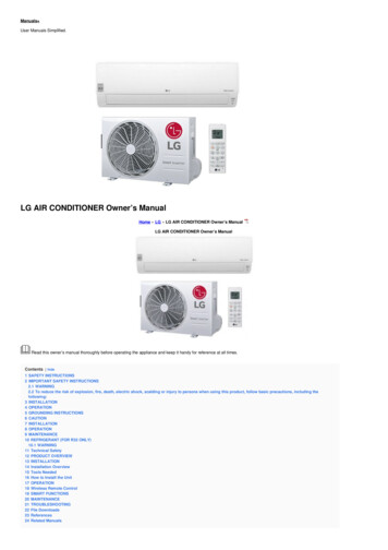
INTRODUCTIONComponent IdentificationLCAMBFDNEKGA — LipB — Main FrameC —PlatformD — Lip CylinderJIHE — Powerpack (Motor/Pump/Reservoir)F — Platform CylinderG— Clean Sweep Removable SectionH —Maintenance Prop Lock-OutJ— Maintenance PropK —Toe Guards (2 used)L —Control BoxM —Raise ButtonN—ARTD Switch (option)THEORYThe EH dock leveler uses hydraulic logic andone‑button operation for ease of use.The dock leveler can be operated remotely using theRAISE button (M) on the control panel .Platform (C) is raised by depressing and holding theRAISE button (M). This activates an electric motor(E) which, in turn, drives a hydraulic pump. Thehydraulic pump forces oil into the platform cylinder(s)(F), causing the platform to rise. Releasing theRAISE button allows the platform to lower.8When the platform rises to the highest point of travelleft in the platform cylinder, a sequence valve inthe Powerpack directs fluid flow to the lip cylinder,extending the lip.With the lip fully extended, the raise button may bereleased, allowing the leveler to float down on to thetransport vehicle for loading or unloading.*See Operating Instructions for a complete operationguide.4111-0004 — May 2015
INSTALLATIONPlacard Installation Instructions Owner is responsible for the installation and placement of product placards. Make sure placard is in plain view of dock leveler operations. Suggested placement of placard is near control box attached to electricalconduit by using nylon tie. If there is no control box present, mount placardon wall to the immediate left of leveler at eye level.Control BoxPlacardNylon Tie(Placard placementshown as referenceonly.)Conduit4111-0004 — May 20159
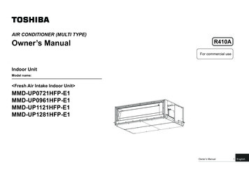
INSTALLATIONPrepare PitAC10”CLB14”DCLA—Distance (Pit Width) B— Distance (Dock Floor-to-Pit C— Distance (Pit Length) D— Distance (Pit Corner‑to‑Corner) (Top,(Front and Rear)Floor) (All Four Corners)(Both Sides of Pit)Bottom, and Both Sides)Post safety warnings and barricade the workarea at dock level and ground level to preventunauthorized use of the dock leveler beforeinstallation has been completed.Failure to follow the installation instructions canresult in damage to dock leveler, the facilities, and/or serious personal injury or death.Only trained installation professionals with theproper equipment should install this product.NOTICEDO NOT remove the shipping bands around thedock leveler lip until instructed to do so.Before lowering the dock leveler into the pit, thefollowing must be performed:1. Remove all debris from the pit and sweep the pitclean.2. Check the entire dock leveler pit for properconstruction according to approved/certified pitdrawings. Make sure pit is square by making thefollowing measurements: Measure pit width distance (A) at both frontand rear of pit. Measure dock floor-to-pit floor distance (B) atall four corners. Measure pit length distance (C) at both sides. Measure corner-to-corner (diagonal) distance(D) at both sides. Take measurements at dockfloor level and at pit floor level. If any measurement is off by more than 1/8in. (3.18 mm), contact Systems Inc. TechnicalServices before proceeding.3. Make sure the field junction box for the dockleveler (E) is at the correct location per pitdiagrams.104111-0004 — May 2015
INSTALLATIONPrepare Dock LevelerNOTICEADO NOT remove the shipping bands (B) aroundthe platform lip and leveler frame at this time. Theshipping bands are needed to hold the levelertogether during the installation process.1. Remove any control panel and bumpers that maybe banded to the frame of the dock leveler.DO NOT remove the shipping bands (B) aroundthe platform lip and leveler frame at this time.NOTICEBA— Lifting Bracket (2 used)B — Shipping BandsPoweramp dock leveler’s are designed withinstallation in mind. Each unit is shipped with liftingbrackets (A) fastened to the platform side joists.Post safety warnings and barricade the work area atdock level and ground level to prevent unauthorizeduse of the dock leveler before installation has beencompleted.Failure to follow the installation instructions canresult in damage to dock leveler, the facilities, and/or serious personal injury or death.4111-0004 — May 2015DO NOT overtighten the lifting bracket hardware.Overtightening can damage the weather seal, ifequipped.NOTE: Overall width of platform and lifting brackets(A) must be kept to a minimum to preventinterference between the lifting brackets andthe pit walls as the dock leveler is loweredinto the pit.2. Make sure the mounting hardware of liftingbrackets (A) is snug. The brackets should pivotrelatively freely on the mounting cap screw.DO NOT over tighten.3. Attach lifting chains to lifting brackets (A) and toa lifting device (i.e., hoist or fork truck) having theappropriate lifting capacity and reach.4. Remove wood blocks that are attached to theleveler frame before putting the dock leveler intothe pit.11
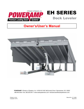
INSTALLATIONInstall Dock LevelerShimStacking MethodsNAAPQRCBDSSee page 16 for Hoist cylinder shimmingEA— Distance (Leveler FrameHeight)B— Shim Locations (UnderRear Vertical Supports)C— Shim Location (UnderMaintenance Prop)*Same as (D)D— Shim Locations (UnderLip Keepers)E— Dock FloorF— Rear Pit Curb Angle12G— StringH— Rear Hinge Frame AngleJ— Distance (Dock Floor-toPit Floor)K— Distance (Top of ShimStack-to-Dock Floor)L— Shim StackM— Dock Leveler FrameN — Pyramid (Preferred)P— Stepped (Acceptable)Q— Offset (Not Acceptable)R — Straight (Not Acceptable)S— Lip Keeper (Shim betweenlip keeper and curb angleas required)JFGHKLM4111-0004 — May 2015
INSTALLATIONNOTE: Poweramp dock leveler’s are designed with anominal 1/2 in. (12.7 mm) shimming distanceto allow for pit inconsistencies.1. Determine height of shim stack (L) for each shimlocation (B) by performing the following:a. Measure leveler frame height distance (A).4. For all EH models, put a 1/4 in. (6.6 mm) thickshim at locations (C and D) . NOTE: A 1/4 in. (6.6 mm) thick shim at locations (Cand D) is used only as a starting point. Thefinal shim stack height will be determinedafter dock leveler is lowered into the pit.b. Measure dock floor-to-pit floor distance (J)at each shim location (B). Write down thedimensions obtained at each location.c. Subtract distance (A) from distance (J) to obtainthe shim height. R epeat for each shim location.NOTICEThe minimum size of the shim that contacts theleveler frame (i.e., the top shim of each shim stack)must be at least 4-1/2 x 4-1/2 in. (114.3 x 114.3mm) to support the full width of the frame rail and toprovide a shelf for a fillet weld.Use the thickest shim stock possible for stabilityand weld penetration purposes. DO NOT usemultiple layers of 1/8 in. (3.18 mm) or thinner shimstock.2. Using the results obtained in step 1, create theindividual shim stacks on the pit floor at locations(B). Build each shim stack (L) using the pyramidmethod (N) (preferred) or stepped method (P) withthe top shim having a minimum size of 4-1/2 x4‑1/2 in. (114.3 x 114.3 mm) and each successivelower shim being larger so the shims can bewelded together using a fillet weld. DO NOT useoffset method (Q) or straight method (R).NOTE: To assist in obtaining an accuratemeasurement of distance (K), use a string(G) pulled tight across the pit opening,directly over the shim locations.3. Verify that each shim stack is at the correct heightby measuring distance (K) [top of shim stack (L)to dock floor]. Distance (K) must equal the dockleveler height (A).4111-0004 — May 2015The dock leveler is heavy. Use a lifting device andchains with the appropriate lifting capacity andreach.Always use the lifting brackets provided with theunit whenever lowering or lifting a dock leveler intoor out of a pit.Failure to follow these instructions may result indamage to dock leveler and/or serious personalinjury or death.5. Using an appropriate lifting device connected tothe lifting brackets, lower dock leveler into the pitso rear hinge frame angle (H) is tight against rearpit curb angle (F) across full width of the levelerframe.6. Allow rear of dock leveler to rest on the rearshims while keeping the front of the dock levelerlevel with the dock floor.7. For all EH models, add shims at front shimlocations (C and D) so front of dock leveler willstay level with dock floor when leveler is restingfully on shims.13
INSTALLATIONABCCDDEFGA— Front of Dock PitB— Dock Leveler Frame3/8 in.(9.5 mm)6 in.(152 mm)C— Side Pit Curb AngleD— Gap [3/4 in. (19 mm)Minimum]8. With rear hinge frame angle (F) tight against rearpit curb angle (G), perform/check the following: Pry between the platform and rear hinge frameangle at locations (E) to make sure rear edgeof platform is parallel to the rear hinge frameangle (F). Gap (D) must exist equally along both sides ofleveler so weather seal (if equipped) will notbind during dock leveler operation.14HE— Pry LocationsF— Rear Hinge FrameAngleG— Rear Pit Curb AngleH— Flare Bevel Weld, Typical(To Fit Spacing)9. If gap (D) cannot be obtained equally at bothsides of leveler, grind or add material at the rearedge of rear hinge frame angle (F) as needed.10. Allow the dock leveler to rest fully on the shimstacks. Check that a smooth and level transitionexists between the dock floor and the dockleveler platform. Add or remove shims asnecessary until a smooth transition is obtained.11. If leveler cannot be squared and/or made levelas instructed in steps 8 — 10, contact SystemsInc. Technical Services.4111-0004 — May 2015
INSTALLATIONNOTICEDO NOT grind or weld if hydraulic fluid or otherflammable liquid is present on the surface to beground or welded.DO NOT grind or weld if uncontained hydraulic fluidor other flammable liquid is present. Stray sparkscan ignite spills or leaks near the work area. Alwaysclean up the oil leaks and spills before proceedingwith grinding or welding.Always keep a fire extinguisher of the proper typenearby when grinding or welding.Failure to follow these instructions may result inserious personal injury or death.NOTICEDO NOT connect the dock leveler electrical wiringand ground connections until all welding has beencompleted.DO NOT ground welding equipment to anyhydraulic or electrical components of the dockleveler. Always ground welding equipment to thedock leveler frame, NEVER to the platform.DO NOT weld continuously along the full lengthof the rear hinge frame angle. This can putunnecessary stress on the leveler components,causing the leveler to malfunction and shorten thelifespan of the affected components.11. With the rear hinge frame angle (F) tight againstthe rear pit curb angle (G), weld the rear hingeframe angle (F) to the rear pit curb angle (G)using a 3/8 in. (9.5 mm) flare bevel skip weld— each weld being 6 in. (152 mm) long. Start at each end with a 6 in. (152 mm) longweld. Space all the other welds out evenlyleaving approximately 6 in. (152 mm) spacebetween each weld.12. Weld front of dock leveler frame (B) to shimslocated under the keepers, then weld the shimsto the front pit curb steel.13. With leveler welded into place, remove theshipping bands from around lip and leveler frame.Failure to follow these instructions may damage themotor, hoist cylinder, wiring, and/or control panel.NOTE: The illustration on the previous page showsa typical weld pattern. The weld patternwill vary slightly depending on size of dockleveler.4111-0004 — May 2015If the platform is rai
dock leveler. Return the dock leveler to its stored position at dock level. Failure to follow posted instructions will result in death or serious injury. SAFETY INFORMATION Cal 26 .510 fo rep ac m nt d s,w i g b , '/u Operation 1. Read and follow all instructions and warnings in the owner's/user 's manual. 2. Use of dock leveler .