Transcription
Combining high-availability and disaster recovery:Implementing Oracle Maximum AvailabilityArchitecture (MAA) on Oracle 10gR2 RDBMSTuomas Nurmela11TietoEnator Processing & Network Oy, Espoo, FinlandTuomas.Nurmela@tietoenator.comAbstract. Increasing dependence of business on 24/7 IT systems setsrequirements to support recovery from hardware, software and operationalerrors and reduce number and length of maintenance windows through onlineand automated or semi-automated system management activities. Theserequirements cannot be satisfied purely by technology let alone a singletechnological innovation on a single layer of a system stack. Oracle has definedMaximum Availability Architecture (MAA) to describe the combination of itstechnologies to support recovery from hardware, software and operationalerrors. With regard to the Oracle RDBMS, these extend the online andautomated management features of the RDBMS. This paper reviews the MAAon Oracle RDBMS with particular focus using Linux as platform to implementthe MAA. The paper also provides a threat analysis to review the extent andlimitations of MAA-based implementation high-availability and disasterrecovery capabilities.Keywords: Databases, high-availability, disaster recovery1IntroductionAvailability is the “ability of a component or service to perform its required functionat a stated instant or over a stated period of time. It is usually expressed as theavailability ratio, i.e. the proportion of time that the service is actually available foruse by the Customers within the agreed service hours” [7, A.2]. Availability can bedefined as being a function of mean time between failure (MTBF) and mean time torecover (MTTR). Therefore, anything that increase of MTBF (or uptime betweenplanned maintenance) and/or decreases MTTR (or downtime during plannedmaintenance) provides high-availability (HA) support. As noted by the definition, atone point, from the end-user perspective, too slow response times can make a systemunavailable in practice .Disaster recovery (DR) can be defined as means of recovering lost data andcapability to restart the service. Whereas high-availability mechanisms typicallyprovide means for service self-healing, disaster recovery can be seen to take thealternative view of backing up and recovering. Typical metrics include recovery pointobjective (RPO, how much data is acceptable to be lost under any circumstances) as
well as recovery time objective (RTO, in what time is the recovery of the system donetechnically or operationally under any circumstances).The increasing dependence of businesses on 24/7 IT systems or regulatoryrequirements to set up such systems leads to near telecom-level availabilityrequirements of 99.999% or 99.9999%. This sets requirements to support recoveryfrom hardware, software and operational errors as well as reduce maintenancewindows. General ICT services market analyst [27] view is that only 20% of failuresare hardware related, where as operational errors (whether unintentional or mistakenactions [26], e.g. truncating a table from the wrong db schema or dropping a tableinstead of truncating) contribute 40% of total failures and application failures,including performance problems, contribute the last 40%. In a survey by Gartner [27],when IT decision makers were asked of the most significant unplanned downtimecontributor, 53 percent indicated application failures (due people or practices failurein e.g. application changes), 21 percent indicated operational failures (due people orpractices relating to infrastructure changes) and 22 percent indicated technology(hardware, OS) or environment (the site) failures.The distribution of errors among error categories gives a clear indication that e.g.operational errors should be addressed in systems design. However, often thearchitecture discussion focuses only on hardware and software faults. E.g. Drake et.al. [1] describe highly available database system design for five or six nineenvironments. Yet they provide no reference as to how the operational errors could beaddressed through systems design and do not discuss how fault tolerant architecturesincrease architecture complexity by definition, therefore potentially only increasingunavailability through operational errors.This paper provides an overview of Oracle database features relating to “MaximumAvailability Architecture” (MAA) [8][13], the best practices approach to utilizingOracle database high-availability and disaster recovery capability. MAA is not asingle technology nor does it assume that all problems could be solved on onetechnology layer of the database stack or only in the database for that matter. RatherMAA provides guidance how different Oracle technologies are supposed to be usedtogether and describes how to minimize unavailability under different types of errorsand changes.The structure of the paper is as follows: Section 2 introduces the main databasetechnologies used in MAA, describing their background, current state in Oracle10gR2 on Linux, operational issues and 11g new features. Section 3 provides anassessment of how these technologies work together under different threat scenariosin a similar manner as discussed in [31] in regards to another database engine.The paper makes a number of assumptions in regards to MAA scope. The paperdoes consider the impact of immediate environment of the database (e.g. applicationserver connectivity through database drivers, IP-network both in terms of LAN andWAN connectivity and the storage area network (SAN) including the storagesubsystem). Beyond the immediate environment, a number of other assumptions limitthe scope: first, the focus is on the Linux implementation of MAA. The architectureimplementation on other platforms, especially on Windows, differs. Second, theassumption is that the processor architecture is based on symmetric multiprocessing.Issues that relate to e.g. non-uniform memory access (NUMA) server architectures arenot discussed. Third, HA design for complete redundancy including access-routing
redundancy and application server redundancy is outside the scope of the paper.Fourth, the competing Oracle or other vendor high-availability or disaster recoveryapproaches are not discussed, the focus is only on MAA approach.2MAA architectural componentsMAA on Oracle database is based on use of Oracle Real Application Cluster (RAC)and Oracle Data Guard. Architecturally this equals a 2 to n node shared disk, shareddistributed cache cluster with one-way replication to another identical cluster.Replication protocol supports either 1-safe and 2-safe schemes [25]. Additionally thelocal shared disks can be mirrored using Oracle Automated Storage Management(ASM). Fast recovery from logical errors (including operational errors) is based onOracle Flashback technologies, enabling selective temporal scan of system changesand applying undo-changes to the database. Finally, backup impact to diskperformance is reduced by block-level incremental backups.The next subsections focus on RAC, Data Guard and Flashback respectively,concluding to short overview of ASM and RMAN backup support. Main focus is onOracle 10gR2 functionality, with an overview of evolution and future developmentswith 11g which relate to high availability, disaster recovery or recovery fromoperational errors. Recovery steps are discussed in more detail in Section 3.2.1 Real Application Cluster (RAC)Oracle Real Application Cluster (RAC) is a shared disk, shared distributed cachedatabase. RAC is a continuation of technology initially introduced in Oracle 6 DECVAX/VMS (in Oracle 8 for all platforms in general) as Oracle Parallel Server (OPS).Oracle 8 introduced the shared distributed cache, but limited this to global enqueues(i.e. locks). With 8i “Cache fusion”, the non-dirty data block sharing wasimplemented. Oracle 9i removed this limitation, allowing use of shared distributedcache for all reads. However, it still mainly relied on an external, OS-vendordependent clusterware to provide server node-level high availability functionality [2,4 pp. 24, 5 pp. 111]. This is not to say that DBMS reliance to OS support is anythingnew or novel, rather being the norm [32]. With Oracle 10g, Oracle made the move toprovide its own clusterware, thereby moving down the stack. Potentially this providesa more integrated solution, reducing the occasionally observed, hard to troubleshootproblems resulting from use of third party clusterware. [2] notes that “the clusterwarewas originally licensed from Compaq. It was originally known as the Oracle ClusterManagement Services (OCMS) and was released on Linux and Windows”.This subsection focuses on the clusterware layer, Oracle RAC layer and additionalservices to support failure masking, taking into account Oracle 11g additions.Additionally, the operational management impact and immediate environmentexpectations are noted.
Clusterware provides a shared-disk active-passive cluster capability on top ofnormal OS services. It functions as a building block for the upper RAC layer.Clusterware contains disk data structures and processes that enable this. It alsoassumes a private network interconnect between nodes for node membershipmanagement and other cross-node activities.Clusterware disk data structures [14, Chapter 1-2, 30, pp.18-19] contain votingdisks and Oracle Cluster Registry (OCR). Voting disks are used by the Clusterware todetect node failure and avoid “split brain syndrome” (i.e., unsynchronized multiplenode access to global resources in case of network partitioning). Clusterware nodesregister themselves to the voting disks, which requires that they have an access path tothe disks. To ensure voting disk availability, MAA configuration uses two additionalcopies of it. Each voting disk should be allocated its own separate 256 MB LUN fromSAN [2].OCR is used to maintain a centralized repository of all clusterware resources andmembers. OCR should be located on its own 256MB LUN from SAN [2]. OCRregistry is supported by a per local-instance OCR process. This provides a cache ofthe OCR content locally on the cluster node. One of the local OCR processesfunctions as a master OCR cache, providing and synchronizing access to the OCRrepository.Instance-specific clusterware processes [14, Chapter 1-2][30 pp. 23-25] containsthree daemon processes. These are the Oracle Cluster Synchronization ServicesDaemon (OCSSD), Event Manager Daemon (EVMD) and Cluster Ready ServicesDaemon (CRSD). All processes are initialized by INIT.CSSD process.OCSSD establishes node and cluster initial state and maintains local view of thecluster. First steps contain establishing cluster configuration, establishing, noderelationships with other nodes and determining location of OCR repository. After thisidentity of the master OCR cache is dynamically established through voting. The nodewhich receives the master OCR cache identity activates itself. This is followed bysynchronization of group and lock resources and activation of other nodes.After initialization the OCSSD functionality consists of Node Membership (NM)and Group Membership (GM) management. NM handles both private network andstorage connectivity checks. GM handles joining the group and managed andunmanaged leaving of group. OCSSD functionality is central to cluster functionality:in case of private interconnect or group membership failure, OCSSD reboots the localnode. In case of OCSSD failure, local node is rebooted.CRSD is the main resource manager of the cluster. It learns the identity of theresources from the OCR and starts them. Upon failure of a resource, CSRD attemptsto restart them up to five times (non-configurable threshold). CRSD is alsoresponsible for initializing the RACGIMON clusterwide health monitoring process.Failure of CRSD results to restart of CRSD by Oracle instance’s PMON backgroundprocess.Cluster resources managed by the CRSD include the Oracle instance, GlobalServices Daemon (GSD), Oracle net listener, Virtual IP and Oracle NotificationServices (ONS) in addition to the local database instance background processes. GSDsupports system management by enabling execution of global (cluster-wide)commands from a single node. Virtual IP provides abstraction of actual IP, to supportfailover handling between RAC nodes. By binding to a floating end-point address,
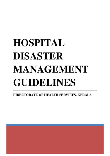
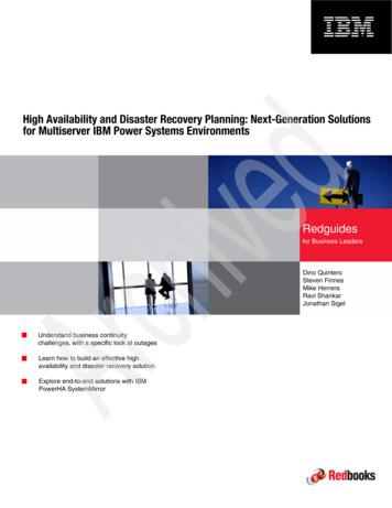
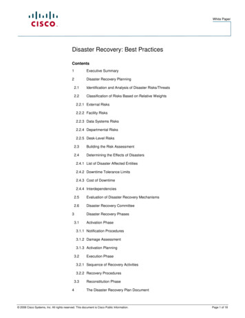
connections can be transferred from a failed host to another cluster member.However, this requires support in the Oracle NET listener and communicationbetween nodes through ONS. Oracle NET listener is connection handler of an Oraclehost. In RAC environments, the services (oracle instance schemas) served by thelistener can be bound to VIP. Both nodes can have their own listener bound to a VIPin case load balancing and failover are configured. RAC-cluster instance loadbalancing can be done on client or server-side as per normal single instance listenerload balancing. In client-side load balancing [2], clients are configured with multipleIP addresses (or VIPs), with the thick driver connecting in a round-robin manner atconnect time. Fault-tolerance can be supported through failover to pre-createdconnections.In server-side load balancing [2], two listeners are configured each withinformation of the other remote listener. PMON processes communicate with eachother periodically to provide state and load information, which is utilized for loadbalancing based on least load.The load balancing in both client- and server-load balancing is done at connectioninitialization, in the listener handshake, prior to binding to the user process. In case ofconnection pools, this means that connection reuse will be incapable of utilizing theload balancing mechanisms. Still, more importantly to HA, additional fault maskingmechanisms exist. These optional enhancements and ONS are discussed later afterRAC layer overview.EVMD publishes CRSD generated events through the ONS peer-to-peer processgroup. It also initiates the RACGEVT process, which manages server Fast ApplicationNotification (FAN) callouts. FAN callouts are server-side executables, which are ranas a response to an event [14, Chapter 6]. Callouts automate basic administration taskssuch as sending an event to a work management system or stopping and startingapplications. Particular event handling definition is contained in a callout file, whichare collected in a specific directory.Finally, OPROCD for monitoring against hangs and IO fencing. On Linux theclusterware utilizes the hangcheck-timer kernel module for monitoring all CPU coresagainst hangs [2][3]. This is done through thread creation and timed sleeps. While notmandatory, MAA recommends its usage. IO fencing mechanism is dependent on theSAN storage subsystem used. Use of SCSI-3 Persistent Reservations on voting diskLUNs are common in todays high-end systems.Clusterwide clusterware processes are processes which have only instancerunning in the whole cluster. RACGIMON is the only clusterwide process. Theprocess handles failover, start and stop of the processes. RACGIMON reuses theshared memory data structures used by local PMON instance to evaluate node states[30, pp.51-52]. On failure RACGIMON is restarted on another node by CRSD. Theclusterware architecture is presented in Figure 1 below.
Oracle RACOracle RACKeyProcessLinux kernel moduleUsed local fileNon-processresourceNetworkNode A clusterwareResourcesResourcesNode B tenerACTIONRACGEVTRACGEVTACTIONRedundant linkOSLUNOptional SPublicLANPrivateFacility borderSANSAN storageSharedresourceSANVoting diskFigure 1: Oracle Clusterware ArchitectureClusterware is basically an OS extension, which provides node fault tolerancemechanisms and coordinates these with the database instance on process faults. TheRAC layer builds on top of this functionality to create a shared-disk active-active 2 ton node cluster. Currently test on a real application in one of the largest installationsshowed near linear scalability for 64 nodes. A node in on RAC layer is called a RACinstance. All the nodes in the cluster form the RAC database. The actualenhancements to standard Oracle database instance functionality are contained inchanged disk structures, new RAC data structures, RAC-specific backgroundprocesses and additional functionality included in background processes part of anormal Oracle database instance.RAC disk data structures relate to enabling RAC instances to access all the filesthat form the RAC database state. These include the database files (containingmetadata, rollback and database data), control file (and its redundant copies), log filesand archived log files. RAC instances have a concurrent, shared access to databasefiles and control files. Under normal operating conditions redo log files and archivedlog files are accessed by the local RAC instance, with each running their own set ofredo logs called a redo log thread. However, these are located in a shared storage area.In case of RAC instance failure another RAC instance can recover the RAC databasestate by acquiring the redo log thread and related archives. Each RAC instancerecords its redo log thread information to the control files to support faster recovery.RAC memory data structures contain the Global Resource Directory (GRD).GRD contains status information of all global enqueues (i.e., locks) and shared datablock buffer cache (BC). These are collectively called GRD resources. For the BCGRD maintains records of the following information [30, pp. 42-46] data block address, location (instance having the most up to date version of resource), mode of reservation, role of block in terms of local (i.e., not yet shared) or global(already shared through distributed cache) System Change Number (local to RAC instance) indicating the most recentchange and indication if the data block is a current or some past image.
GRD is distributed with each RAC instance having its own local part of GRD. This islocated in the instance shared memory allocation, System Global Area (SGA). Themastership over data blocks and related enqueues is determined in node initialization.This happens by determining a hash values for GRD resources and distributingmastership of a ranges of hash values to different RAC instances. However,remastering of a resource mastership can happen as a result of usage patterns or RACinstance failure. GRD resource information is maintained by RAC instance-specificGlobal Enqueue Service Daemons and Global Cache Service Daemons.RAC-specific background processes [14, Chapter 1][30, pp. 32-35] includeGlobal Enqueue Service Daemon (LMD), Global Enqueue Service Monitor process(LMON), Global Cache Service Monitor Daemon (LMSn), Lock Manager process(LCK) and the Diagnostics Daemon (DIAG).LMD functions as a resource access manager, providing access to global enqueuesand data blocks in distributed cache. LMD handles all requests to resources that aremastered (i.e. are in the local part of the GRD), whether these requests are from thelocal or remote instance. LMD does not actually provide resource lock management,this is delegated with service request to LMS functionality (on distributed cache level)and LCK (on local instance non-shared resources, such as other SGA caches). As theprimary resource manager to mastered resources, LMD is also responsible for global(i.e., cross-instance) deadlock detection.LMSn handles the actual block transfer from local instance to requesting remoteRAC instance based on service request queue filled by LMD. The transfer is done bydirect copy from data block buffer cache to remote RAC instance. LMS provides readconsistency by rollback of uncommitted transactions prior to transfer. This is requiredbecause the distributed shared cache functions on the block granularity. LMS alsoinforms the remote instance if the block cannot be acquired due lock typeincompatibility. On successful transfer of block, GRD information is updated.LMON handles the group membership on RAC-layer. It maintains groupmembership through polling local and remote RAC instances. In group membershipchanges LMON is responsible for remastering of GRD resources. In instancerecovery operations, LMON is responsible for determining failed instance prior tostart of cache recovery (a specific part of recovery), which contains recovery of GMDresources. Therefore, LMON can be thought to be analogous to the instance-specificSMON in terms of recovery, functioning on the RAC distributed cache level. LMONis often referred to as Cluster Group Services in Oracle conceptual documentation[14].LCK handles access to local resources that are not shared, e.g. SGA cacheresources and local row-lock information. As such, LCK seems to be a mediatingprocess between the normal Oracle instance functionality and RAC-specificfunctionality. Information on LCK functionality was especially scarce.DIAG is the instance health monitor. It also records process failure dumpinformation to instance alert log.Normal local instance background processes [2] are also affected by RAC to acertain degree. RAC mainly impacts instance monitoring processes as well asprocesses participating to data i/o.Process monitor, PMON, is responsible for monitoring and reinitialization attemptof local non-RAC related processes (both user and background processes). From RAC
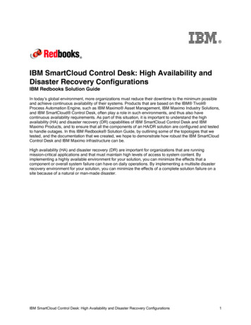
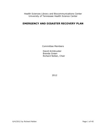
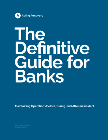
perspective, PMON also handles local listener registration and monitoring for localand – when utilized – remote listeners to support listener failover and server-side loadbalancing.Upon failure of process, PMON handles the clean up of memory data structuresand creates the alert log (with the exception of RAC-specific background processes,for which DIAG writes the alert log entries).System Monitor, SMON, is responsible for system recovery actions during theARIES-like two-phase recovery. Given that RAC is a shared database, SMON of anon-failed instance may be required to carry out recovery of database state from logsand archives on behalf of a failed instance. SMON does not carry out cache recovery,as this is done by LMON.Dirty buffer writer, DBWR, is responsible writing dirty buffer cache blocks to diskunder certain conditions. With RAC, DBWR must coordinate writes with the globalcache services LMD and LMSn processes as well as with the LCK lock manager.The RAC architecture is depicted in Figure 2 below. The RAC instances onlycontain background processes which directly relate to RAC, a number of normalOracle instance background processes are not depicted.KeyProcessLinux kernel moduleUsed local fileNon-processresourceNetworkInstance dant linkOptional elementFacility borderSGAGRDDIAGDIAGDBWRDBWR PMONLGWRLGWRARCHFileInstance BSPFILESPFILEOracle ClusterwareBCSMONARCHOracle rdwarePrivateSANSANREDO AARCH AControl fileSANREDO BARCH BData file(s)Figure 2: Oracle Real Application Cluster ArchitectureThe figure assumes archives are shared through SAN instead of copied to multiplelocations.Optional mechanisms contain enhancements enabling failure masking throughutilization of Oracle Notification Service (ONS). Failure masking from clients such ase.g. application servers is important to enable the whole system to benefit from thedatabase HA capabilities.ONS is a publish and subscribe system for non-reliable messaging. It isimplemented as a set of ONS daemons, one running on each node and on eachinvolved client such as middle-tier servers, with ONS daemons replicating locally
received cluster events to others. Events include up, down and restart of registeredclusterware and RAC instance components.Transparent application failover (TAF) framework is a RAC failure maskingmechanism functioning on application layer. TAF enables transparent read-query reexecution. It does not support continuation of transactions, maintenance of nondefault session parameters or database session-related information (such as PL/SQLprocedure state). TAF use requires an additional configuration to the client- or serverside load balancing utilizing fault-tolerance and is independent of ONS.To extend failure masking capabilities to handle transaction continuation forconnection failure, Fast Application Notification (FAN) –based services need to beutilized either in the driver layer or in the application code [2]. FAN is based onONS. FAN is not transparent like TAF, as specific event-handling is required.Because typical middle-tier connections utilize connection pooling to establish alogical connection to a database, the connection pooling layer seems to fit well forinternal plumbing required for such event handling. This is the concept behind Oracle10gR2 Implicit Connection Cache (ICC) [30, pp.261-298, 581-592]. As ICC utilizesONS, the combination is called Fast Connection Failure (FCF). ICC functions as anyJDBC 3.0 cache. If underlying connectivity is based on a type 2 driver (“thick driver”,Oracle OCI driver), ICC is able to handle connectivity-related ONS events behind thescenes, transparently to the application. It does this by wrapping the physicalconnection to a logical connection. In a case of client connection failure to a RACinstance listener, the physical connections are closed, new connections are establishedto an available RAC node and these are wrapped to the same logical connections.Other events are forwarded to the application layer (which then again may have itsown logic for handling transaction errors etc). ICC does not do connectionrebalancing in case of up event.Beyond failure masking, ONS events can also be utilized for more advanced formsof load balancing, such as the one provided by Load Balancing Advisory service. Thisuses listener service specific goals (definable through PL/SQL packageDBMS SERVICE procedure MODIFY SERVICE) to maintain load sharing,informing the application of load imbalances.Immediate environment in a MAA configuration should support RAC through anumber of redundancy mechanisms. These include (i) use of two networkinterconnects (NICs) and Linux network interconnect bonding of production andprivate interconnect network access, to support HA of network interfacing, (ii) use oftwo host bus adapters (HBAs) and 3rd party HA drivers to support HA of SANinterfacing and (iii) dual switching infrastructure for both LAN and SAN network toavoid single points of failure in the immediate network. Finally, (iv) either Oraclestorage management or external storage redundancy mechanism should be used toensure data availability. Clusterware provides a verification tool, by which the correctconfiguration can be ensured to a certain extent.From operational management perspective, RAC supports all the normal Oracleonline and automated management features. In terms of rolling upgrades, RAC is alimited solution: system and hardware upgrades can be done, but Oracle patching issupported only in explicit, qualified one-off patches (i.e., patch sets, version migrationand some one-off patches cannot be done without off-line maintenance). On the otherhand, since RAC is an active-active cluster, there is no downtime from taking a node
down and the expected application staleness time (“brownout period”) due to transferof from one node to another only impacts individual sessions [28].Oracle 11g RAC new features offer mainly administrative improvements. Inaddition to these, from clusterware perspective [19], new voting disks can be addedonline. From shared database improvements perspective [20], runtime load balancinghas been incorporated into the OCI thick driver functionality. Additionally, 11g aRAC instance can act as a global coordinator for a distributed transaction spanningmultiple RAC instances.2.2 Data GuardOracle Data Guard [17] is a one-way replication database mechanism supporting 1safe (i.e., commit on primary site is sufficient) or 2-safe replication (i.e., data iscommitted to standby prior commit acknowledgement) [21]. Data Guard [2][6,Chapter 7, 13] is a continuation of what was first introduced in Oracle 8i as OracleStandby Database. The Standby database focused only on physical log shipping. Itsupported read-queries if put into a non-standby mode to do so (but had to beswitched back to standby mode). Also, once the original site was recovered after thedisaster, the original standby database could not be converted back to standby mode;rather the whole standby database had to be re-established (a particular problem whenrunning a non-identical production and standby environments). Likewise, if therewere gaps in transfer of log records, these had to be manually resolved. With Oracle9i, role switchover support was established. Spotting of gaps became automatic, basedon log shipping gaps or lack of heartbeat from primary node. Also, Data GuardBroker was established to support a third-node controlled, automated switchover and2-safe support was established as one of the possible data protection modes. With9iR2, the physical log shipping architecture was complemented with logical standbydatabase. With 10gR1, support for usage of Data Guard with RAC was established.Flashback database support (i.e. support for point in time recovery of the productiondatabase could be imitated on the standby database) was also established. With10gR2, support for automated failover management through Data Guard Broker wasestablished. Most of the other developments relate to performance and manageabilityimprovements of the Data Guard itself. Both 10g releases have also extended thelogical standby database implementation by reducing a number of limitationsconcerning its use in terms of database data types and object types (index types, nonstandard tables etc).This section focuses on the 10gR2 Data Guard physical and logical standbydatabase architectures, providing an overview of the processes and di
Fourth, the competing Oracle or other vendor high-availability or disaster recovery approaches are not discussed, the focus is only on MAA approach. 2 MAA architectural components MAA on Oracle database is based on use of Oracle Real Application Cluster (RAC) and Oracle Data Guard. Architecturally this equals a 2 to n node shared disk, shared