Transcription
The Effect of Joint Design and Volume Fractiono n Friction Welding Properties ofA360/SiC (p) CompositesFor this friction welding system, the joint strength is best with 360AI-360AI andworst with 360AI/10v-%-360AI/10v-% SiC particulate compositesBY C. B. LIN, C. K. MU, W. W. W U A N D C. H. H U N GABSTRACT. This research uses a rotationfriction welding system with 360AI and360Al/5v-%-10v-% (v-% volume fraction percent) SiC particulate compositesutilizing both identical and different materials and two joint designs. In joint design I, one side is a lead angle and theother is a plane. In joint design II, bothsides are planes. From the experiment, itwas noted that using joint design Iachieved better joint strength. The jointstrength is best with 360AI-360AI andworst with 360AI/10v-%-360AI/10v-%SiC particulate composites. 360AI-360AIhas a ductile fracture with dimples, whilethe 360AI/10v-%-360AI/10v-% SiC particulate composite has a low-ductile fracture. The 360AI/10v-%-360AI/10v-% SiCparticulate composites are fractured inthe Zpl zone, while the others are fractured in the interface between the Zplzone and the Zpd zone. For the joint systems using different materials, the fractureis in the interface between the Zpl zoneand Zpd zone, where the quantity of SiCparticulate is higher. In the heat-affectedzone (HAZ) for identical materials, theZpl hardness value is smaller than Zud;for the different materials, the hardness inZpl is half of the two Zud hardness totalvalues.IntroductionSiC particulate reinforced aluminumalloys (SiC/AI) offer several advantagesrelative to monolithic aluminum alloys,such as high Young's Modulus, high hardness, wear resistance, low thermal expansion coefficient and good thermalconductivity. These alloys are useful foraerospace and transportation industryapplications, including airframe structures, automotive front disc brake rotors,C B. LIN, C K. MU, W. W. WU and C H.HUNG are with the Department of Mechanical Engineering, Tamkang University, Taiwan,P. R. China.100-s I MARCH 1999turbocharger impellers (Ref. 1), aircraftwing skins and missile bodies (Ref. 2).The joining technique plays a veryimportant role in the manufacture ofcomplicated and special-function SiC/AIproducts or structures. The followingmethods are often used for joining SiC/AIcomposites: Fusion w e l d i n g - - including gastungsten arc welding (GTAW) (Ref. 3), resistance welding (RW) (Ref. 4) and laserbeam welding (LBW) (Ref. 5) - - is amethod that requires a great deal of energy, resulting in chemical reactions thatare responsible for a variety of defects,such as oxide films, porosity, cracks andthe formation of the intermetallic compound AI4C3 (Refs. 6-8). These defectsdecrease the strength of the weld joint. The diffusion bonding method (Ref.9) requires a high vacuum or heatingequipment; therefore, it is more expensive and has restricted application. Mechanical interlocking or mechanical fasteners (Ref. 10) are methodsthat lack ductility; therefore, stress concentration is easily produced in weldingpoints (such as bolt joints or rivets) thatmay lead to catastrophic fractures. The friction welding (FRW) method(Reg. 11-12) is classified as a solid-statewelding process in which heat is generated by friction from the relative motionKEY WORDSRotation Friction WeldingJoint DesignSiC ParticulateCompositesJoint StrengthHeat-Affected Zoneof the parts to be welded. The applicationof an axial force maintains intimate contact of the parts and causes plastic deformation of the material near the weldinterface. Deformation is largely restricted to the volume of material adjacent to the original interface by anadiabatic shear process (Ref. 13). Frictionwelding is used with SiC/AI compositesbecause energy is produced in the workpiece after opposite friction, resulting inless input energy; the heat-affected zone(HAZ) is more narrow; and hard, brittleintermetallic compounds are not easilyproduced, thus increasing the weldingstrength (Ref. 13).The advantages of friction welding areas follows:1) Previous handling is simple; twowelding sides can be cleaned throughfriction.2) Filler material and a protective atmosphere are unnecessary.3) A high production rate can beachieved; therefore, it is economical inoperation. In fact, friction welding hasbecome a widely used process for joining both similar and dissimilar materialsin industries such as the automotive industry (Ref. 14).Sassani, et al. (Ref. 15), shows thatcopper and steel friction welding, usinga compatible metal interlayer, can increase welding strength approximately40%. Yilbas, etal. (Ref. 16), indicates thatif there are oxide films and grease on thesurface of the workpiece, the weldingstrength will be lower. If the surface hasbeen cleaned and roughness has beendecreased, it is beneficial to the weldingstrength. Decreasing the whirling speedwill decrease welding strength and theburn-off length. Decreasing the arresttime will also decrease the weldingstrength because of the decreasedforge displacement. Ellis, et aL (Ref. 17),indicates that the joint strength of2648AI/14% SiC particulate composites
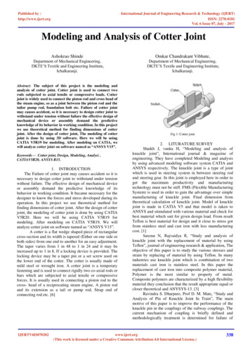
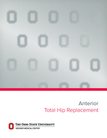
}.A 30"k AD1 12.7 mmD2 20 mmL 15mmR 4 . 5 mm(A)LD1 12.7 mmD2 20 mmL 15mmR 4.5 mm(B)Fig. I - - The size o f workpiece for: A - - Joint system I; B - - j o i n t system II.,h droullC rB, urn2. ROTARYJAW3a, 3b. WORKPIECEFig. 2 -Fig. 3 - - The microstructure of: A - - 3 6 0 A Ibase material; B - - 3 6 0 A I / S v - % ; C - 3 6 0 A I / I 0v-% SiC particulate composites.5. STABILIZERSchematic diagram o f friction welding system.is about 380 N/mm 2 with friction welding. In addition, if the workpiece goesthrough solid-solution, quench and agingtreatments after friction welding, the jointstrength can rise to 431 N/mm 2, which isclose to the previous 2648AI jointstrength of approximately 455 N/mm 2.This research investigates joining360AI and 360Al/Sv-%-10v-% SiC particulate composites by rotation frictionwelding. It also probes the design endof the workpiece and the influence of SiCparticulate content on the joint strengthand hardness of the welding zone. Themicrostructure of the welding zone hasbeen observed by an optical microscopeand the resulting conclusions arediscussed.Experimental ProcedurePreparationoftheMaterialThe material system of this researchwas adopted to 360AI/SiC particulatecomposite, with the quantity of SiC particulate 5v-% and 10v-% and the maincomposition of the base material 360AI(9.5%Si-0.5%Mg). SiC particulate wasirregular in shape, (z-phase, with theaverage size of the particles 15 lam.Preparation of the 360AI/Sv-%, 10v% SiC particulate composites was as follows: the original 360AI/40wt% SiCparticulate composite ingots were produced by ingot metallurgy (Ref. 18) andthen the diluting method was used onthis material to produce the two abovementioned composites.The diluting process was as follows:the 360AI ingots were first placed in a690 4- 5oC (1274 4- 41 F) electric resistance furnace and remelted. A properquantity of 360AI/40wt-% SiC particulate composite was then added, meltedtogether to provide degassing and stirredevenly. Next, the oxidation film and slagplaced on the upper layer of the meltwere cleaned. The system was stirredbefore casting, and the melt was stirredrepeatedly to prevent the specific gravitySiC particulate from sinking to the bottom of the crucible and influencing concentration of SiC particulate in thecomposites. The metal mold was placedin a 300 3 C (527 37.4 F) constanttemperature system to proceed with thecasting. Finally, the workpiece was removed after casting and put in a 300 43 C air furnace to homogenize for 4 h.FrictionWelding360AI and 360AI/5v-%-10v-% SiCparticulate composite friction weldingworkpieces were manufactured first; thena welding workpiece pair was manufactured - - Fig. 1. As shown in Fig. 1A, oneworkpiece of the welding point is planeand the other is the lead angle design; inFig. 1B, the workpieces of the weldingpoints are both plane. The welding workpiece was put into a 200 4- 3 C (392 4-\A/FI FIINIC, RF FARCI-I 11PPl F/kAFN!T I ln1.
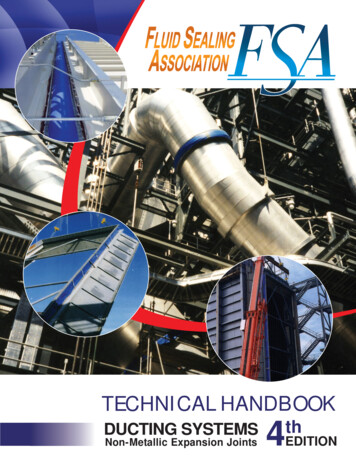
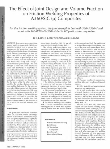
37.4 F) air furnace to anneal for 2 h toeliminate the residual stress of machining.The welding point surface, Ra, was 2.5IJm. Before welding, the workpiece wasput in a container filled with acetone andthe grease on the workpiece weldingplanes was cleaned by ultrasonic vibration. The finished workpiece was thenfixed for friction welding by using the rotation friction-welding machine - - Fig. 2.The process of friction welding occurredwhen different quantities of 360AI andSiC particulate composite materials wereplaced in a workpiece of similar or dissimilar quality; the workpiece was fixedat a rotation speed of 800 rpm; and thefriction pressure of 5.6 MPa was maintained for 8 s. Finally, the same forgingpressure as used in the friction processwas held for 10 s to enhance bonding.Metallographic PreparationFirst, the 360AI, 360AI/5v-%-10v-%SiC particulate composites and all of thefriction-welded workpiece sections werecut and polished with 400- and 1200-gritcarbimet papers and 1-1Jm AI203 particulate suspension polishing liquid. Finally, the samples were etched by 10%NaOH solution after polishing and themorphology was observed using the OPTIPHOT-100 Nikon optical microscope.Tensile TestThe flash was machined from the weldsbefore testing with thegauge length of the testspecimen at 29 mm.i//////Fi /'/ /I//!All of the frictionwelds were tested atroomtemperatureZud i.i using an Instron tensilemachinewithacrosshead speed of5 mm/min. The fracture stress was calculated from the load atfailure, divided by theFig. 4 - - Schematic of the HAZ showing the fully plasticized (Zpl),original cross-sectionpartially deformed (Zpd) and undeformed (Zud) regions (Re 20).area. Three measurements were taken foreach of the weldingstrengths to calculateof 10 gf, a loading time of 30 s and a loadtheir average data.ing speed of 100 lam/s. Three measureA JEOL-JSM840A scanning electronments were taken for each of the hardnessmicroscope (SEM) was used after gildingvalues to calculate their average data.gold for 1.5 min to observe the tensilefracture surface morphology.Results a n d D i s c u s s i o n!Y.Sf",,;Hardness TestSiC Particulate in Matrix DistributionThe Mitutoty Mvk-G1 micro-Vickershardness tester was used to test the hardness of the welding zone, with a loadingThe 360AI, 360AI/ 5v-% and 360AI/10v-% SiC microstructures are shown inFig. 3. The 360AI base material consistsZudZudFig. S - - The microstructure of 360AI-360AI (Type A) composites in: A - - The HAZ; B - - the Zpl zone.102-s I M A R C H 1999
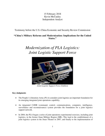
ZudZudFig. 6 - - The microstructure of 360AI-360AI/Sv-% (Type B) composites in: A - - The HAZ; B - - the Zpl zone.Fig. 7 -The microstructure of 360AI-360AI/10v-% (Type C) composites in the HAZ.of a primary c crystal, with interdendriteeutectic silicon. The SiC particulate in thecomposite (Fig. 3B, C) clusters betweenthe dendrite arms. The degree of clustering was more serious in the 5v-% SiC material than in the 10v-% SiC material.According to Ellis's theory (Ref. 19), theheterogeneity of the 5v-% and 10v-% SiCparticulate quantity is calculated to be0.99 and 0.92. The reason for the clustering is SiC particulate is pushed to theinterdendritic regions during thesolidification process. When the SiCparticulate quantity is increased, SiCparticulate will restrict the growth of thedendrite and lower its degree of jostleclustering.The Microstructure of the SiC Particulate inthe Welding ZoneAccording to Midling, et al. (Ref. 20),the HAZ after friction welding is dividedinto three zones: 1) the fully plasticizedregion (Zpl); 2) the partly deformed region (Zpd); and 3) the underformed region (Zud), as shown in Fig. 4. For fixedfriction (forge) pressure and friction timewhen using joint design I, the microstructure of 360AI base material and360AI/5v-%-10v-% SiC particulate composites in the welding zone are shownin Figs. 5-9. In Fig. 5A, the HAZs after360AI friction welding are shown. Themicrostructure in the Zpl and the Zpd isdifferent from the enlarged previous baseWELDING RESEARCH SUPPLEMENT[ 103-s
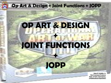
Fig. 8 - - The microstructure of 360AI/Sv-%-360AI/Sv-% (Type D) composites in the HAZ.Fig. 9 - - The microstructure of 360AI/10v-%- 360AI/10v-% (Type E) composites in the HAZ.material. In Fig. 5B, it can be observedthat the Zpl zone microstructure becomes tiny eutectic silicon, which is thendistributed evenly in the 360AI basemetal. This is due to the process of friction welding-- the welding planes rotatemutually, which then produce frictionheat and shear stress. The shear stressmay effectively break the base materialgross primary crystal, dendrite and theeutectic silicon. There is tiny eutectic silicon in the Zpd zone, which goes into theZpl zone by plastic flow field direction.Figure 6A shows the microstructure of360AI and 360AI/5v-% SiC particulatecomposites in the HAZ. An obvious plastic field can be observed in the Zpd zoneof the 360AI; however, the plastic flow inZpd of 360AI/5v-% SiC particulate composites is less obvious because the SiC104-s I MARCH 1999particulate effectively prevents the plastic flow. In Fig. 6B, it can be seen in theZpl zone that the tiny eutectic silicon andSiC particulate are distributed evenly inthe matrix, which is different from theclustering of SiC particulate in the Zud of360AI/5v-% SiC particulate composites.The reason why SiC particulate clustersfrom the Zud to the Zpl is that the plasticflow and shear stress under friction welding makes SiC particulate compositeagain, which is beneficial to the weldingcharacter.Figure 7 shows the microstructure of360AI and 360AI/10v-% SiC particulatecomposites in the HAZ. Eutectic siliconand SiC particulate are distributed evenlyin the Zpl zone. Moreover, it can be observed that the microstructure of 360 AIin the Zpl zone is eutectic silicon enteringthe Zpl zone by plastic flow. It is notablethat eutectic silicon near the 360AI Zpdzone is less likely to enter the Zpl zoneafter forming in the Zpl zone because theSiC particulate, which has gone into theZpl zone, can restrict its entrance. It canalso be seen that the plastic field near theZpl in 360AI is more complicated because the SiC particulate of 360AI/10v-%SiC particulate composites can effectivelyrestrict the plastic flow since the plasticflow in the Zpd zone of 360AI is largerthan in the composite materials. Afterbeing plasticized in the HAZ, the harder360AI/10v-% SiC particulate compositesare pushed into the softer 360AI base material during forging.Figures 8 and 9 show the microstructures of 360AI/5v-% SiC and 360AI/10v%SiC particulate composites for the
width is greater than in those with bothsides of composite materials.Table I - - The Zpl Width of the DifferentJoint SystemsJoint System0%-0%0%-5%0%-10%5%-5%10%-10%Width (mm)ABCDE1.661.361.04O.940.80identical material welded workpiece inthe HAZ. The plastic flow field near theHAZ in this welded system is not veryobvious because the plastic flows of thetwo sides are identical. Under plasticization and forging, the two sides have identical push power and SiC-particulateresistant plastic flow.Integrating Figs. 5-9, the width of Zpdis the same for all welds, and the widthof Zpl is shown in Table 1. For the identical material, the 360AI joint system isthe largest and the system of 10v-% SiCparticulate is the smallest. For the different-quality materials, the width is lowered following an increase in the totalquantity of SiC particulate. In addition,the 360AI and SiC particulate (10v-%) iswider than the SiC particulate (5v-%)identical composites material weldingbecause the increase of SiC particulatecan restrict the plastic field. Finally, inthe joint system, one side is base material and, due to the contribution to plastic flow made by the base material, theThe Hardness of the HAZFor fixed friction (forge) pressure andfriction time when using joint design I,the different joint system hardness distribution in the HAZ is shown in Fig. 10.The hardness in the HAZ is divided intothree zones: the first is referred to as theZ u d zone, whose hardness is that of thebase material workpiece hardness. Thesecond zone, the Z p l zone, has hardnessof a mixed quality after the two sideswere plasticized. The third zone, the Z p dzone, has hardness that is the transforming zone. There is dynamic recovery nearthe Zpd zone, which lowers the degree ofhardness (Ref. 20). The different joint system's effects on the three zones' hardnessare as follows:1) For the identical-materials jointsystem, the hardness in the Zpl is lessthan in the Zud - - Fig. 10A-C. This is because the higher friction heat annealingsoftens it in the Zpl zone. The hardness ofthe 360AI base material joint system islowest in the center of the Zpl zone because the annealing temperature is highest in the center. For the SiC particulate5v-% and 10v-% joint system, the hardness maintains the same value in the Zplzone. Although the annealing effect softens the matrix in the Zpl zone, SiC particulate may restrict the dislocationactivity effectively, with the effect of therestriction greater than the effect of basematerial annealing. Further, the SiC particulate 5v-%-5v-% composites joint system hardness is larger than 360AI-360AIin the Zpl zone because the distributedSiC particulate 5v-%-5v-% joint system'srestrictive dislocation activity effect isgreater than the annealing effect afterfriction heat. Otherwise, SiC particulate10v-%-10v-% hardness is less than 5v%-5v-% in the Zpl zone. Midling, et al.(Ref. 14), showed the increase of SiC particulate c o n c e n t r a t i o n produced much [ I I il !' more friction heat, so there may havebeen more frictional heating and anneal-ing effect of the 10v-%-10v-% materialweld.2) For the different-materials jointsystem, the 360AI-360AII5v-% SiC particulate composites and 360AI-360AI/10v-% SiC particulate composites areshown in Fig. 10D and E; the hardnessin the Zpl zone is half of the total ofthe two Zud hardnesses. Therefore, forthe360AI(Hmv70)-360AI/5v-U4)l li , .Zti.L: ! , ' %(Hmv80) joint system, the Zpl degreeof hardness is about Hmv75; for the360AI(Hmv70)-360AI/10v-%(Hmv90)system, the Zpl degree of hardness isabout Hmv80. This is because the composite and base materials are evenlymixed. The increasing quantity of SiC inthe Zpl zone increases the degree ofhardness; 360AI-360AI/10v-% is greaterthan 360AI-360AI/5v-% SiC particulate.Integrating Fig. 10, the hardness of the360AI base material is smaller than the360A1- 360AJ. '10%- 10%5%- 5%8O80 70?01.50.-2.2-1.8-I,.4 -! 41.641.20.2 0.6 !1.4 .g 2.2-1.8 -1.4 -1 41.6D i # (am)41.2 0.2 0.6I m. (mm)1.4 1.81-2. '1 -1.6-!41.4 0.20.81,42(c)(B)(A)0% 10%0%- 5%90 . 7o . 7o,2.2 .8-. .4 -I 4 6.@20.2 0.6 Dimn (ram)(D)1.4 1.8 2.2-I,8 -I.4-Il41.6 41.2 0.2 0.6I1.4 1.8Dismnc.e (mnO(E)Fig. 10 - - The hardness in friction welding affect zone of."A - - 360AI-360AI (Type A); B - - 360AI/Sv-%-360AI/Sv-% (Type B); C - - 360AI/10v-%360AI/10v-% (Type O; D - 360AI-360AI/Sv-% (Type D); E - 360AI-360AI/10v-% (Type E)joint system.WELDING RESEARCH SUPPLEMENT [ 105-s[
360AI360AIi.:4, , ' ,. :, ' 200prn360AI/5v-%360AI/5v-%360AI / 10v-%360AI/10v-%- " oA,360AI / 5v-%;:71(D)360AI/10v-%360AIFig. 11 - - The tensile fracture zone of.' A - - 360AI-360AI (Type A); B - - 360AI/Sv-%-360AI/5v-% (Type B); C - - 360AI/10v-%-360AI/10v-% (TypeC); D - - 360AI-360AI/Sv-% (Type D); E - - 360AI-360AI/I 0v-% (Type E) joint system.hardness of the Zpl for all welds exceptthe 360AI-360AI joint system. The enhanced hardening in the Zpl zone is dueto the dislocation generated to accommodate the difference in CTE between106-s I M A R C H 1999the reinforcing particulate and the matrix(Ref. 21 ).Tensile Fracture TypeThe tensile fracture types of differentjoint systems are shown in Fig. 11, fromwhich the following can be observed:1) For the identical-materials jointsystem, the 360AI and 360AI/5v-%360Al/5v-% SiC particulate composites
Table 2 - - The Joint Strength of Friction Welding by Joint Design ITensilePropertiesJointSystem5.6 MPa8s( y0.2O/o(MPa)UTS (MPa)( f(MPa)ABCDE0% q able 3 - - The Joint Strength of Friction Welding by Joint Design IITensilePropertiesJointSystem5.6 MPa( y0.2%(MPa)UTS (MPa)( f(MPa)8sFig. 12 - - Fracture surface o f m o r p h o l o g y(SEM): A - - 3 6 0 A I - 3 6 0 A I (Type A); B - 360AI/10v-%-360AI/10v-% SiC (Type E) particulate composites.fracture in the interface between the Zplzone and the Zpd zone - - Fig. 11 A andB, respectively. Because the stress is concentrated due to the alignment of SiC particulate, cracking easily occurs in thiszone. The 360AI/10v-% SiC particulatecomposites system fractures in the Zplzone. Increasing the rate of void nucleation at the reinforcing phase by increasing the SiC particulate density of thiszone (Ref. 22) easily produces lowductile fractures - - Fig. 11C.2) For the different-materials jointsystem, 360AI-360AI/5v % SiC particulate composites and 360AI-360AI/10v-%SiC particulate composites, tensile fractures occurred in the interface betweenthe Zpl and the Zpd where the quantityof SiC particulate was higher-- Fig. 10Dand E.The Joint StrengthThe 360AI-360AI/5v-% and 10v-% SiCparticulate composite workpieces use jointdesign I and II, whose joint strengths areshown in Tables 2 and 3, respectively.From this table comparison, for the identical-joint system, using joint design I canachieve better joint strength, and the friction pressure and forging adopted by thisresearch are lessthan those in Refs. 15-17.Joint design II is the design method formerly used. Making use of joint design 22.6121.6136.2136.2136.2103.5106.8118.7107.2can achieve better joint strength becausethe tangent velocity used farthest from thecenter is greater and smaller in the centerduring the process of friction welding.Therefore, the material farthest from thecenter can produce obvious plastic flow.This plasticized zone will fill in the leadangle gap because of friction pressure. Thisfilled plastic zone can only hinder the following plasticized zone, which increasesthe chance of welding. Also, because jointdesign II does not have a lead angle design,the plastic materials farthest from the center will leave and decrease the weldingzone. The ensuing welding, which contributes to the HAZ, comes from the center. Because the tangent velocity of thiszone is low (especially in the center, whichis zero) the friction heating and degree ofplasticizing is smaller, lowering its diffusion welding ability and joint strength. Forfixed friction (forge) pressure and frictiontime when using joint design l, the jointstrength rankings are separated as follows:360AI-360AI 360AI-360AI/ 10v-% 360AI-360AI/5v-% 360AI/ 5v-%360AI/5v-% 360AI/10v-%-360AI/ 10v%. This is because, for the identicalmaterial(360AI-360A1 360AI/5v-%360AI-5v-% 360AI/10v-%-360AI/10v-%)joint system, in the 360AI-360AI system,the base material toughness is better andcan delay its breakage. There is even eutectic silicon in the Zpl zone and the stressconcentration is smaller, which can effectively increase tensile strength. Moreover,for the 360AI/10v-%-360AI/10v-% system, the SiC particulate density of the Zplzone is high and its material quality willproduce low-ductile fractures in the Zplzone. If one side of the workpiece is thebase material (360AI-360AI/10v-%,360AI-360AI/5v-%) joint system, because360AI provides much more strain energyfor absorption, it can delay breakage and117.2106.3increase the strength of the composite materials (10v-% strength is better than 5v-%).The SEM fracture surface morphologyafter 360AI-360AI and 360AI/10v-%360Al-10v-% workpiece tensioning isshown in Fig. 12. From Fig. 12A, itcan beobserved that the fracture surface of 360AI360AI has ductile fractures with dimples.Moreover, 360AI/10v-%-360AI/ 10v-%has low-ductile fractures - - Fig. 12B.ConclusionsThe following conclusions have beenreached:1) The microstructure of the Zpl zoneis different from that in the Zud. For360AI/SiC particulate composites, clustering SiC particulate turns into evenlydistributed SiC particulate.2) For the identical materials, the360AI joint system has the widest Zplzone, and the 360AI/10v-% SiC particulate composites joint system has thesmallest. For the different quality materials, the width is decreased by an increasein the total of the two workpiece particlequalities. In addition, the increasing360AI-360AI/10v-% joint system iswider than the 360AI-360AI/5v-% jointsystem.3) The hardness in the HAZ is dividedinto three zones: Zud, Zpl and Zpd. Forthe identical materials, the Zpl hardnessis lower than the Zud; for the differentmaterial, the Zpl hardness is half of thetotal of the two Zud hardness values.4) For the tensile fracture type, theidentical materials, 360AI and 360AI/5v%, break in the interface between the Zplzone and the Zpd zone, and 360AI/10v% breaks in the Zpl zone. For differentmaterials, the breaks occurred in the interface between the Zpl zone and theZpd zone, where the quantity of SiC par-WELDING RESEARCH SUPPLEMENT I 1 0 7 - s
ticulate is higher.5) Using joint design I results in better joint strength than with design II.6) For the joint strength, the sequenceis 360AI-360AI, 360AI-360AI/ 10v-%,360AI-360AI/5v-%, 360AI/5v-%-360Al5v-%, 360AI/10v-%-360AI/10v-%.7) The tensile fracture surface morphology 360AI-360AI has dimple ductilefractures and 360AI/10v-%-360AI/10v% has low-ductile fractures.AcknowledgmentThis work was supported by TheNational Science Council, Taiwan,Peoples Republic of China.References1. Huda, D., El Baradie, M. A., andHashmi, M. S. J. 1993. Metal-matrix composites: Materials aspects. Part II. Journal of Materials Processing Technology37(1-4): 529-s to541-s.2. Lienert, T. J., Baeslack Ill, W. A.,Ringnalda, J., and Fraser, H. L. 1996. Inertiafriction welding of SiC-reinforced 8009aluminum. Journal of Material Science 31 (8):2149-s to 2157-s.3. Kennedy, J. R. 1972. Microstructuralobservations of arc welded boron-aluminumcomposites. Welding Journal 51 (3): 120-s to124-s.4. Hersh, M. S. 1971. Correlation betweenboron/aluminum sheet quality and resistanceweld quality and strength. Welding Journal50(12): 515-s to 521-s.108-s I M A R C H 19995. Dahotre, N. B., McCay, M. H., andMcCay, T. D. 1989. Laser processing of aSiC/AI alloy metal matrix composite. Journalof Applied Physics 65(11): 5072-s to 5077-s.6. Devletian, J. H. 1987. SiC/AI metalmatrix composite welding by a capacitordischarge process. Welding Journal 66(6):33-s to 39-s.7. Iseki, T., Kameda, T., and Maruyama, T.1984. Interfacial reactions between SiC andaluminum during joining. Journal of Material5cience 19(5): 1692-s to 1689-s.8. Ahearn, J. S., Cooke, C., and Fishman,S. G. 1982. Fusion welding of SiC-reinforcedAI composites. Metal Construction 14(4):192-s to 197-s.9. Lienert, T. J., Baeslack III, W. A.,Ringnalda, J., and Fraser, H. L. 1996. Inertiafriction welding of SiC-reinforced 8009aluminum. Journal of Material Science 31 (8):2149-s to 2157-s.10. Hall, I. W., and Manrique, F. 1995.Surface-treatment of carbon-fiber for aluminum-alloy matrix composites. ScriptaMetal. 33(12): 2037-s to 2043-s.11. Wang, K. K., and Nagappan, P. 1970.Understanding aluminum welding. WeldingJournal 49(9): 419-s to 425-s.12. Wang K. K., and Lin, W. 1974. Flywheel friction welding research. WeldingJournal 53(6): 233-s to 241 -s.13. Spindler, D. E. 1994. What industryneeds to know about friction welding. WeldingJourna173(3): 27-s to 42-s.14. Midling, O. T., and Grong, O. 1994. Aprocess model for the friction welding ofAI-Mg-Si alloys and AI-SiC metal-matrixcomposites 1. HAZ temperature and strain-ratedistribution. Acta Metal. 42(5): 1595-s to1609-s.15. Sassani, F., and Neelam, J. R. 1988.Friction welding of incompatible materials.Welding Journal 67(11 ): 264-s to 270-s.16. Yilbas, B. S., Sahin, A. Z., Cobon, A.,and Abdul Aleem, B. J. 1995. Investigationinto the properties of friction-welded bars aluminium. Materials Processing Technology54(1): 76-s to 81-s.17. Ellis, M. B. D., Gittos, M. E., andThreadgill, P. P. I. 1994. Joining aluminumbase metal matrix composites. MaterialsWorld 12(8): 415-s to 417-s.18. Lin, C. B. 1994. U.S. Patent No.5401338.19. Ellis, M. B. D. 1996. Joining of AIbased metal-matrix composites: A review.Materials and Manufacturing Processes 11 (2):45-s to 61-s.20. Midling, O. T., and Grong, O. 1994. Aprocess model for friction welding of AI-MgSi Alloys and AI-SiC metal-matrix composites2. HAZ microstrucure and strength evolution.Acta Metal. 42(5): 1611 -s to 1622-s.21. Arsenault, R.J., and Shi, N. 1986. Dislocation generation due to differences between the coefficients of thermal expansion.Materials Science and Engineering 81 (1):175-s to 187-s.22. Humphreys, F. J. 1988. Mechanicaland physical behavior of metallic and ceramiccomposites. Proceedings of the 9th Riso International Symposium on Materials Science. S.I. Andersen, H. Lilholt, and O. B. Pedersen,eds. Rockslide Denmark: Riso National Laboratory, pp. 51-74.
of Joint Design and Volume Fraction Friction Welding Properties of A360/SiC (p) Composites For this friction welding system, the joint strength is best with 360AI-360AI and worst with 360AI/10v-%-360AI/10v-% SiC particulate composites BY C. B. LIN, C. K. MU, W. W. WU AND C. H. HUNG ABSTRACT. This research uses a rotation