Transcription
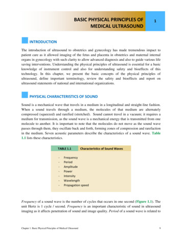
BASIC CHARACTERISTICS OF THEULTRASOUND EQUIPMENT2INTRODUCTIONPerforming and successfully completing an ultrasound examination requires multitude of skillsthat include the medical knowledge, the technical dexterity, and the know-how to navigate thevarious knobs of the ultrasound equipment. Today’s ultrasound machines are complex and quiteadvanced in electronics and in post-processing capabilities. Being able to optimize the ultrasoundimage is much dependent on the understanding of the basic functionality of the ultrasoundequipment. This chapter will focus on the review of various components of the ultrasoundequipment and the basic elements of image optimization. The following chapter (chapter 3) willintroduce some helpful scanning techniques.THE ULTRASOUND EQUIPMENTUltrasound technology has changed drastically over the past decade allowing for significantminiaturization in the design and manufacturing of ultrasound equipment. The spectrum ofultrasound equipment today includes machines that can fit in the palm of one’s hand and highend machines that can perform very sophisticated ultrasound studies. It is important to note thatbefore you acquire ultrasound equipment, you should have an understanding of who will beusing the equipment, for which medical purpose it is intended to be used, in which environmentit will be used and how will it be serviced. The answer to these important questions will help inguiding you to the appropriate type of ultrasound equipment for the right setting. For instance,ultrasound equipment destined for low-resource (outreach) settings should have specialcharacteristics such as portability, sturdiness and a back-up battery in order to adjust tofluctuation in electricity. Furthermore, ultrasound equipment designed for the low-resource(outreach) setting should be easily shipped for repairs and service.Ultrasound TransducersUltrasound transducers are made of a transducer head, a connecting wire or cable and aconnector, or a device that connects the transducer to the ultrasound machine. The transducerhead has a footprint region (Figure 2.1) where the sound waves leave and return to thetransducer. It is this footprint region of the transducer that needs to remain in contact with thebody in order to transmit and receive ultrasound waves. A gel is applied to the skin/mucosasurface of the body to facilitate transmission of ultrasound waves given that sound waves do nottransmit well in air. Each transducer also has a transducer (probe) marker located next to thehead of the transducer in order to help identify its orientation (Figure 2.2). This probe markerChapter 2: Basic Characteristics of the Ultrasound Equipment30
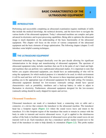
can be a notch, a dot or a light on the probe’s head. The use of this probe marker in handling thetransducer and its orientation will be further discussed in the following chapter (Chapter 3).Figure 2.1: Footprint of a curvilinear abdominaltransducer. The footprint region is where thesound waves leave and return to the transducer.Figure 2.2: Probe marker of a curvilinearabdominal transducer. The probe marker isessential in the proper handling and orientationof the transducer (discussed in chapter 3).Transducers are produced in an array of shapes, sizes and frequencies and are adapted forspecific clinical applications. In general, transducers for cardiac applications have smallfootprints. Vascular transducers have high frequencies and are linear in shape and obstetric andabdominal transducers are curvilinear in footprint shape in order to conform to the shape of theabdomen (Figure 2.3).Figure 2.3: Abdominal transducer used for obstetric applications.Note the curvilinear shape of the footprint, which helps toconform to the abdominal curvature.Chapter 2: Basic Characteristics of the Ultrasound Equipment31
Linear transducers produce sound waves that are parallel to each others with a correspondingrectangular image on the screen. The width of the image and number of scan lines is uniformthroughout all tissue levels (Figure 2.4). This has the advantage of good near field resolution.Linear transducers are not well suited for curved parts of the body as air gaps are createdbetween the skin and transducer (Figure 2.5).Figure 2.4: Transverse plane of the fetal chestin the second trimester of pregnancy using alinear transducer. Note the rectangular screenimage and a good near-field resolution.Figure 2.5: Linear transducer used for obstetricscanning in the late second trimester of pregnancy.Note the gap produced between the transducerfootprint and the abdominal wall (white arrows). Thiscan be eliminated by simply applying gentle pressureon the abdomen.Sector transducers produce a fan like image that is narrow near the transducer and increase inwidth with deeper penetration. Sector transducers are useful when scanning in small anatomicsites, such as between the ribs as it fits in the intercostal space, or in the fontanel of the newborn(Figure 2.6). Disadvantages of the sector transducer include its poor near field resolution andsomewhat difficult manipulation.Chapter 2: Basic Characteristics of the Ultrasound Equipment32
Figure 2.6: Sector transducer; note the small footprint, which allows for imaging innarrow anatomic locations such as the intercostal spaces or the neonatal fontanels.Curvilinear transducers are perfectly adapted for the abdominal scanning due to the curvature ofthe abdominal wall (Figure 2.3). The frequency of the curvilinear transducers ranges between 2and 7 MHz. The density of the scan lines decreases with increasing distance from the transducerand the image produced on the screen is a curvilinear image, which allows for a wide field ofview (Figure 2.7).Figure 2.7: Ultrasound image of the fetal head using a curvilinear transducer. Note thatthe image is curvilinear in shape (arrows) and has a wide field of view.Chapter 2: Basic Characteristics of the Ultrasound Equipment33
Transvaginal transducers, like other endocavitary transducers, have a small footprint and theirfrequencies are typically in the range of 5-12 MHz (Figure 2.8). They are designed to fit in smallendocavitary spaces with the footprint at the top of the transducer (transvaginal) or at the dorsalaspect of the transducer (rectal). When performing a transvaginal ultrasound examination, aclean condom, or the digit of a surgical rubber glove, should cover the transvaginal transducer.Ultrasound gel should be placed inside and outside the protective cover in order to facilitate thetransmission of sound.Figure 2.8: The head of a transvaginal transducer; note the smallfootprint (labeled) at the top of the transducer.Protocols for ultrasound transducer cleaning should be adhered to in order to reduce the spreadof infectious agents. Both the transabdominal and the transvaginal transducers should be wipedbetween ultrasound examinations and disinfection of the transvaginal transducer should beperformed according to national or manufacturer guidelines (1).Controls of the Ultrasound EquipmentUltrasound equipment has a wide array of options and features. These features are typicallyoperated from either the console of the ultrasound equipment, a touch screen monitor or acombination of both (Figure 2.9). The basic controls that you need to familiarize yourself in theearly stages of ultrasound scanning are the following:Chapter 2: Basic Characteristics of the Ultrasound Equipment34
Figure 2.9: Ultrasound equipment showing a wide array of knobs forcontrol of various features. Most ultrasound equipment have akeyboard and a trackball on their consoles.Power or Output Control: This controls the strength of the electrical voltage applied to thetransducer crystal at pulse emission. Increasing the power output increases the intensity of theultrasound beam emitting and returning to the transducer, thus resulting in increase in signal tonoise ratio. Increasing the power results in an increase in ultrasound energy delivered to thepatient. It is therefore best practice to operate on the minimum power possible for the type ofstudy needed. Resorting to lower frequency transducers can help achieve more depth whileminimizing power output.Depth: The depth knob allows you to increase or decrease the depth of the field of view on themonitor. It is important to always maximize the area of interest on your monitor and decrease thedepth of your field of view, which enlarges the target anatomic organs under view. Figures 2.10A and B show the importance of depth control in obstetrical scanning.Gain: The gain knob adjusts the overall brightness of the image by amplifying the strength of thereturning ultrasound echo. The overall brightness of the image can be increased or decreased byturning the gain knob clockwise or counterclockwise respectively. Figures 2.11 A and B showthe same ultrasound image under low and high gain settings.Chapter 2: Basic Characteristics of the Ultrasound Equipment35
Figure 2.10 A and B: Figures A and B represent transverse view of the same fetal head at the level ofthe biparietal diameter. In A, the depth (white double arrow) is increased, resulting in a small head,whose anatomic details are consequently difficult to see. In B, the depth is reduced, which allows for alarger head thus improving visualization.Figure 2.11 A and B: Figures A and B represent transverse view of the same fetal head at the level ofthe cerebellum. In A, the gain is too low and in B, the gain is adequate. Note better visualization ofintracranial anatomy with a higher gain (B). Adjusting the gain to the correct level comes withexperience.Time Gain Compensation (TGC): The Time Gain Compensation (TGC) allows adjustment ofbrightness at a specific depth of the image. The upper knobs increase or decrease brightnesscloser to the transducer footprint and the lower knobs increase or decrease brightness farthestfrom the transducer footprint. Figure 2.12 shows the TGC location on one of the ultrasoundmachine console. As a general rule, in transabdominal ultrasound, the upper field gain knobsshould be kept slightly to the left than lower field ones (in this way the eye of the operator canfocus on the deeper part of the screen where the fetus is). The reverse is true with transvaginalultrasound, where the region of interest is often in the near field.Chapter 2: Basic Characteristics of the Ultrasound Equipment36
Figure 2.12: Time Gain Compensation (TGC) on an ultrasound consol. The upper andlower knobs adjust brightness in the upper and lower fields respectively (labeled). Theoverall knob (labeled) adjusts brightness in the whole image.Focal Zones: The focal zones should always be placed at the depth of interest on the ultrasoundimage in order to ensure the best possible lateral resolution. Multiple focal zones can be used tomaximize lateral resolution over depth; however this will result in a slower frame rate and is thusless desirable when scanning moving structures such as in obstetrics or the fetal heartspecifically.Freeze: The freeze knob allows the image to be held (frozen) on the screen. While the image isfrozen measurements can then be taken and organ annotations can be applied to the image beforesaving it. Furthermore, the option to “cineloop” (scroll) back to previous time frames is an optionthat is available on most ultrasound equipment. This is a very important function in obstetricultrasound imaging, as it assists in capturing frames during fetal movements, such asmeasurement of long bones.Trackball: The Trackball or Mouse pad is used for moving objects on the monitor and forscrolling back in freeze mode. It has a multi-function and can be used in conjunction with caliperplacement, screen annotation, or moving the zoom or Doppler boxes to the desired location.Res or Zoom: Some ultrasound equipment has this function, which allows magnification ofareas of the ultrasound image displayed on the monitor in real time. The trackball is used inconjunction with the Res/Zoom knob to choose the area for magnification.2-D: The 2-D knob stands for the 2-D mode of scanning or the traditional B-mode imaging. Bstands for brightness (mode). In this mode, the image is displayed in grey scale and is comprisedof pixels arranged in a sector or linear fashion with various shades of grey thus representing theChapter 2: Basic Characteristics of the Ultrasound Equipment37
intensity of the returning signal (Figure 2.13). When the operator presses this knob, thetraditional 2-D image is activated. This knob is also used to get back to grey scale imaging fromcolor Doppler and/or Pulsed Wave Doppler.Figure 2.13: Two-dimensional ultrasound image of the fetal chest at the level of the fourchamber view. Note the various gradation of grey with the ribs being the brightest (echogenic)followed by the lungs and heart (labeled). The amniotic fluid (AF) is black in color (anechoic)reflecting a weak intensity of the returning echo.M-Mode: The M-Mode knob activates the M-Mode function of the ultrasound machine. MMode stands for Motion mode and in this function an M-Mode cursor line appears on the uppersection of the image with an M-Mode display on the lower part of the image (Figure 2.14). TheM-Mode display corresponds to the anatomic components that the M-Mode cursor intersects.The M-Mode is used primarily to document motion, such as cardiac activity of the fetus in earlygestation (Figure 2.15).Figure 2.14: M-Mode cursor line (dashed line) is shown through the fetal heart(small bracket) in the upper image. Note the corresponding M-Mode display (largebracket) in the lower image showing cardiac motion.Chapter 2: Basic Characteristics of the Ultrasound Equipment38
Figure 2.15: M-Mode applied in the first trimester for documentation of fetal heartactivity. Reflections in the M-Mode tracing (asterisks) represent cardiac motion.Calipers are measuring fetal heart rate (FHR) at 144 beats per minute (bpm).Color Flow: The color flow knob activates color flow or color Doppler, which adds a boxsuperimposed on the 2-D real-time image on the screen. The operator can control the size andlocation of the color box on the 2-D image. Color flow or color Doppler detects blood flow in theinsonated tissue and assigns color to the blood flow based upon the direction of blood flow. Byconvention, red is assigned for blood flow moving in the direction of the transducer (up) andblue is assigned for blood moving in the direction away from the transducer (down). Theoperator can also control the velocity scale of blood flow (pulse repetition frequency) and thefilter or threshold of flow. These parameters are important in assessing various vascular beds.Note that the display of color flow follows the physical principles of Doppler flow and thus if theultrasound beam is perpendicular to the direction of flow, color Doppler information will not bedisplayed on the monitor (see chapter 1 for details). Newer ultrasound equipment tries toovercome this limitation by providing other means for display of blood flow such as PowerDoppler which primarily relies on wave amplitude and B-flow (not to be confused with BMode) both of which are relatively angle independent.Pulsed Wave Doppler: The pulse wave Doppler (Pulsed Doppler) or Spectral Doppler knobactivates the pulse Doppler display. In this display a cursor line with a gate appears in the upperhalf of the screen and a pulse or spectral Doppler display appears in the lower half of the screen(Figure 2.16). The pulsed wave Doppler gate can be moved by the operator and placed within avessel as imaged by color Doppler. Typically, this mode is activated when a vessel is firstidentified or suspected and after color flow Doppler is activated. Pulsed Doppler allowsobtaining specific quantitative information about a vessel such as S/D ratio of the umbilicalChapter 2: Basic Characteristics of the Ultrasound Equipment39
artery (Figure 2.17). Flow towards the transducer is displayed above the baseline and flow awayfrom the transducer is displayed below the baseline. The operator has the option to invert thedisplay of the Doppler spectrum in order to display the waveforms above the line (Figure 2.16).See chapter 1 for more details.Figure 2.16: Pulsed wave Doppler of the umbilical artery. Note that the Doppler gateis placed within the umbilical artery as seen in the upper part of the image and thespectral Doppler waveform is displayed in the lower part of the image. The spectralDoppler is inverted to display the waveforms above the line.Figure 2.17: Pulsed wave Doppler of the umbilical artery at the abdominalinsertion. Doppler waveforms are shown in blue color. S stands for flow at peaksystole and D stands for flow at end diastole. Note the Doppler indices in theright upper corner of the image (yellow). For more details, refer to Chapter 1.Chapter 2: Basic Characteristics of the Ultrasound Equipment40
Measurement: The measurement function or knob can also be displayed as Measure or Cal(Calculation) on the ultrasound console. This function allows the operator to measure, indifferent formats, various objects on the screen. When the measure button is pressed, a caliperappears on the screen. Use the trackball to move the caliper to the desired location and set it.Once set, a second caliper appears, which can be set in similar fashion. Stored normogramswithin the ultrasound equipment allow for determination of gestational age and estimation offetal weight when various fetal biometric parameters are measured.STARTING AN EXAMINATIONBefore starting an ultrasound examination, it is important to ensure that essential informationabout the patient is entered into the ultrasound equipment in order to be able to save ultrasoundimages on the hard drive of the ultrasound machine, accurately calculate gestational age inpregnancy and print ultrasound images for documentation purposes. Minimal relevantinformation that is required to be entered includes the patient’s name, date of birth and first dayof the last menstrual period. On many ultrasound equipment, a knob identified as “Patient orStart” leads you to this screen where this information can be entered (Figure 2.18). If you do notenter this information or any other patient identifier at the initiation of your examination (patientname); most ultrasound systems will not allow you to print or save an image from yourexamination.Figure 2.18: Consol of an Ultrasound equipment showing the knob identified as“Patient” (white circle), which leads you to a screen on the monitor (not shown)where patient identifiers are entered before initiating the ultrasoundexamination.Chapter 2: Basic Characteristics of the Ultrasound Equipment41
When a patient returns for a follow-up examination, modern ultrasound equipment allows you toretrieve the patient information automatically without a need to reenter the data.DOCUMENTING AN EXAMINATIONAn ultrasound report is required at the conclusion of the ultrasound examination. Chapter 15details the parameters of an ultrasound report in obstetrics and gynecology. It is important toknow that image documentation is an essential component of the ultrasound examination andreport. Images can be produced in paper format or stored digitally on the ultrasound equipment.Several ultrasound systems have knobs for images, which can be formatted to allow for printingon a thermal printer and for saving a digital copy in a DICOM format on the equipment harddrive. The operator also has the option of downloading and saving a study on an external harddrive or a USB jump drive. This is an important function in the low-resource setting as it allowsfor exchange of cases for educational and consultative function. Typically these knobs can beformatted for these functions, such as for thermal paper printer, for saving on the hard drive andfor downloading to the USB outlet. A permanent copy of the ultrasound report, includingultrasound images, should be kept and stored in accordance with national regulations.References:1) American Institute of Ultrasound in Medicine (AIUM) Guidelines for Cleaning andPreparing Endocavitary Ultrasound Transducers Between Patients (Approved 6/4/2003) r 2: Basic Characteristics of the Ultrasound Equipment42
Ultrasound equipment has a wide array of options and features. These features are typically operated from either the console of the ultrasound , a touch screen monitor or a equipment combination of both Figure 2.( 9). The basic controls that you need to familiarize yourself in t