Transcription
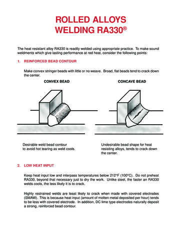
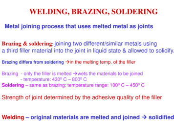
WELDING, BRAZING, SOLDERINGMetal joining process that uses melted metal as jointsBrazing & soldering: joining two different/similar metals usinga third filler material into the joint in liquid state & allowed to solidify.Brazing differs from soldering in the melting temp. of the fillerBrazing - only the filler is melted wets the materials to be joined- temperature: 4300 C – 8000 CSoldering – same as brazing; temperature range: 1000 C – 4500 CStrength of joint determined by the adhesive quality of the fillerWelding – original materials are melted and joined solidified
Mainly from Chapter 39:Arranged according to the subjectflow.
Joinability/Weldability Wettability: Hydrophobic or HydrophilicFluidity: Gap, Surface tension, material.Cleanliness: Oxide removal, etc.Prevention from furtheroxidation/Contamination
Soldering joints : soft types:1.2.Tin & Lead (60:40, 50:50, 40:60) – tf 2400 CLead & Silver (97:3) tf 3100 CFor filling 20/30 % tin – lead composition – cheaperCleanliness – Critical to the strength of the jointOxide have to be removed from the surfaces before joiningCleaning methods 1. Using fluxes (chemical action)2. Abrasive removal (mechanical action)3. Ultrasonic cleaning (acoustic action)Fluxless Soldering: Gold coated, Ultrasonic, Inert atmosphere.
Heating:- required to melt the filler (by any method: furnaces, torch, electricalresistance) Typical, the use of soldering iron heat is applied from the iron and solder is meltedand it adheres to the surface of the joint (usually, as a wire) The joined parts should be also heated to improve the joining process Ultrasonic soldering the soldering iron is actuated with 20KHzSOLDERING JOINTS:
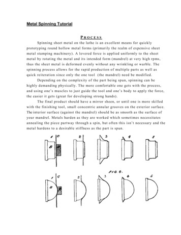
BRAZING: Similar to soldering but at temp 4500 C, still lower than meltingtemperature of the brazed metal parts.Here, the capillary attraction is driving the fillermetal into the joint (clearance is very small)For different fillers different recommended clearances to improve the strengthof the joint Copper no clearance silver alloy 0.04 – 0.05 mm brass 0.5 – 0.75 mm
The clearances are estimated at the brazingtemperature. Estimate the initial dimensions based on theexpansion coefficient gap or interference
BRAZE WELDING a joining process where the capillary attraction is not usedto distribute the filler metal. The molten filler is deposited before brazing is done. special fluxes are used (Borax) to: remove the oxideimprove the fluidity of the fillerswet the joint surfaces
Brazing Materials:copper alloyssilver alloysaluminium alloysBasic joint types in brazing:
Quality of joints:Rule of thumb: stronger joints for larger contact areastronger joints for optimal clearancestronger joints for appropriate brazing materialBrazing of pipes – in hydraulic works, can be performed in different ways Induction brazing (brazing process named by the method that is used to heatassembly), furnace, dipping, torch, electricThe brazing operation must be preceded by cleaning and setting of the proper gap[jigs are used to hold the parts at their position during brazing]Typical Process Assembly of pipes, carbide tips,radiators, heat exchangers, repair of casting
Chapter 35
WELDINGMetal joining process – without different metal added between.Coalescence– can be obtained by heat and/or pressure, metallurgical conditionsBY HEAT hot welding (melted partly at the joint)BY PRESSURE metallurgical process at the level of the intermolecular forces cold welding (attraction forces between atoms at the contact surface)
PROBLEMS: Keeping weld clean – coalescence is improved by cleanliness of surface to be welded Surface oxides –removed before welding fluxes are used during the welding, thefluxes burn and produce slag because they float as slag on the molten metal andprotect it from atmospheric contamination (made of SiO2 additives). In gas welding, the filler metal rod is often coated with flux In electrical arc – welding – the electrode is coated with flux or the flux is added aspowder over the welding seem A non – oxidising atmosphere is created and the welding is shielded against oxygen(oxidation) Inert gasses used to protect the weld created from oxygen
CLASSIFICATION
Chapters 36, 37 and 38
WELDING PROCESSES1.FORGE WELDING (FOW) Welding with use of pressure & heat – not much in use today Hot metal are hammered together until welded (but not melted)2COLD WELDING (CW) – no heat is used coalescence through rapidapplication of pressure Surface must be very clean, flat in order to bring the atoms of metal veryclose Done by a punch-press or hammer – a kind of cold working process
3. OXYFUEL GAS WELDING (OFW):old method metals are heated with aflame produced from reaction of oxygen with acetylene use of a filler – metal to fill the gap (the same metal) to a state of fusion no pressure is used Oxygen from air stored in steel cylinders at a pressure of 2000 psi (140 bar) acetylene gas (C2H2)- obtained from reaction between calcium carbide water(or in bottles (cylinders) – 250 psi /17 bar) mixing & burning of acetylene oxygen torch (the flow controlled by valves)
pure oxygen provides a flame with temperature much higher than using air(up to 35000 C)Combustion reactions: Control of the flow rates of oxygenand acetylene – very important.This affects the characteristic of theflame which depends on O2/C2H2 ratio Three types of flame can be obtained:REDUCING, NEUTRAL & OXIDIZING
NEUTRAL flame the widest application : the inner luminous cone has 1:1 ratio(stochiometric) of O2 and C2H2 First part of reaction (C2H2 O2 2CO H2) occurs near the torch tip SAFETY – a real problem: eye protection from the radiation explosionEx: C2H2 fitting has left hand valve and O2 right hand thread, to avoid mistakes. Utilisation: gas –flame welding largely replaced by arc or resistance weldingexcept for repair work, field welding or some special applications(thin metal sheet welding, artistic welding )
ADVANTAGES:by gas welding even with thin materials, temperatures can be easily controlledDISADVANTAGES:exposure of heated metal to various gases from the atmosphere,without shielding contamination;distortion of thin metal parts (non uniform heating)more expensive replaced by shielded metal arc welding & inert gas metal welding
4. Pressure – Gas Welding. (PGW) – To make butt joints between bars or ends heatedwith gas flame but below the melting point temperature, and then forced to join togetherunder pressure Can be considered as solid phase weld this method requires special equipment
5. Arc Welding – in generalProcess in which coalescence is obtained by heat produced from an electric arccreated between the work piece and an electrode. – no pressure applied;The electrode or filler metal is also heated to a liquid state and deposited intothe joint to make the weld.The two electrodes: 1. Workpiece and 2. Electrode an electric circuit is created By closing the electrodes, the arc is formed at low voltage (28V), high current(few hundreds of A) the electric energy is converted into an arc with intense heat release which createshigh temperature, around 39000 C difficult to control the temperature by on –off method only there is no possibility to control the temp. as in gas welding Traditionally, DC was used with heavy and expensive rectifiers
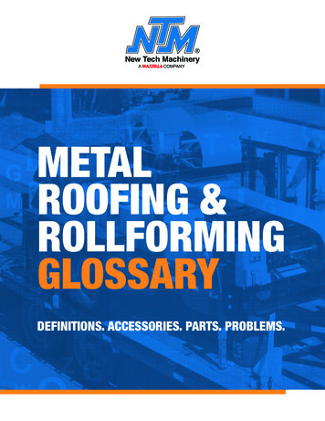
Two procedures: 1. Straight polarity electrode –(e- pulled to job, Heavy ions to electrode, more heat atelectrode more melting and filling of electrode butshallow weld penetration in job. 2. Reversed polarity electrode The reverse happens, more heat at the job more melting ofjob heavier ions result in deeper weld penetration.
Now: AC more spread because of the simplicity of the equipment(no rectifiers but just an inexpensive transformer) the electrode used usually melts at temp. below the temp. of the arc electrodes consume in the welding process this electrode is moved towards the workpiece when consumed. also, not consumable electrode, made of tungsten are used. The method needs to feed the weld filler.
TYPES OF ELECTRODES1.Bare electrodes: limited use for iron and mild steel low quality materials2.Fluxed electrodes: with light coat of flux eliminate undesirable oxides andprevent their formation3.Heavy coated electrode: very used presently for shielded metal arc welding (95%) a gas shield is provided around the arc to eliminate the undesirable oxides andnitrides to be formed in weld metal. It also provides the weld metal with aprotective slag coating, which prevents oxidation of the surface metal duringcooling* the type of coating of the flux is considered in terms of the type of welding andthe materials that must be welded: flux compounds Coating consists of slagforming compounds
TYPES OF ARC WELDING PROCESS5a. Shield Metal Arc Welding – (SMAW) – uses heavy –coated electrodes5b. Gas Tungsten Arc Welding – (GTAW)Special purpose such as stainless steel welding to prevent oxidation The inert gas substitutes for the shielded electrodes (Ar, He) Electrode – non consumable – by tungsten NO SLAG Filler metal must be provided
5c. Gas Metal Arc Welding inert gas used for shielding againstatmosphere (CO2, N2 - inexpressive) consumable bare electrode are used for non – ferrous metals –(aluminium) NO SLAG
5d. Flux Cored Arc Welding (FCAW) Flux core – inside the electrode SLAG coats the hot weld gas produced from flux burning protects the weld
5e. Submerged – Arc welding (SAW) Suitable for automation (automation process) Arc is shielded by a blanket of granular flux fed from a hopper during welding Bare electrode is fed into the granular flux which laid down along the seam to bewelded Welding action takes place beneath the flux which laid down along the seam to bewelded Welding action takes place beneath the flux cover Intense heat of the arc produces a pad of molten metal in the joint the sametime, a portion of the granular flux which will float on top of the molten metal wilburn and produce slag will protect the melted metal from the oxidation After cooling, the fused slag solidifies is removed easily flux can be requiredEx: vessel welding
Only flat surface or surfaces with large aperture can be welded high welding rate can be obtained with mechanised process good weld control obtained thick metal plates can be welded5f. Stud Welding –(S.W) – arc welding process to end –weld metal studs to flatsurfaces Special welding gun is used to hold the stud when the trigger is pressed, the stud is lifted to create an arc, and then, forcedagainst molten pool by backing springs the operation – automatically controlled – no skill required frequency 60 operations/min
6. Resistance WeldingPhenomenon when high current is passed througha joint and heat is releasedJoule’s effect E I2Rt Heat and pressure are used to join parts: suitable for automation robots perform this job. For plates and sheets heavy current is passed through both parts causing localheating at the joint (the highest resistance) Welding is completed by application of pressure low voltages 4-12 V at high flow (current) from transformers When the current passes through metal, most heat at the joint point greatestresistance (in the electrical path, which is at the interface of the sheets)
Power flow 30-40 KVA/ in max. 10 sec. Time Pressure to complete the weld is 4000-8000 psi (28-55 MPa) Resistance of the workpiece is determined by the type of the metal and itsthickness it is usually small Electrodes – high conductivity copper, do not melt, has cooling circuit Resistance between the surface depends on:- the finish of the surface- the contamination of surface- the pressure applied- the contact area of surface
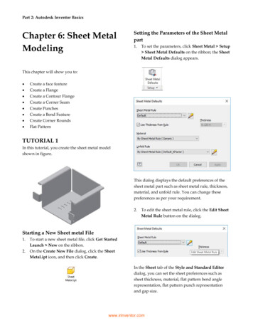
6a. Resistance spot welding (RSW): two or more sheets of metal are hold betweenmetal electrodes.Welding cycle: electrodes contact themetal (pressure is applied) Known as squeeze time Current is passed between electrodes the temperature increases at thecontact point the metals melt the electrodes squeeze the material weld time Current is shut – down pressureincreased hold timepressure is released off timeweld nugget is formed
6b. Resistance Seam Welding (RSEW) Continuous weld on two overlapping pieces of sheet metal – can be leak proof(tanks, reservoirs) It is like frequency spot welding process, with the current applied periodically. Typical welding speed ( 60 in/min)Types of seam- lap seam weld- finish seam weld – only one side of the joint is visibleWater cooling of electrodes is neededSeam welding used in manufacturing of metal containers,automobile parts, tanks, pipes.
6c. Butt welding a sort of resistance welding to weld two identical parts bypressure and heat generation just on the surface using high frequency current6d. Pipe Welding most of seam welding welding, in (shaping or forming)Sides of the strips brought together and current is passed through RESISTANCE BUTT WELDING
Another method : high frequency induction heating of the surfacebefore the material is squeezed together HIGH FREQUENCY WELDING OF PIPESMACHINES FOR RESISTANCE WELDING- stationary single spot machine- portable single spot machine- multiple spot machine- robotsPORTABLE SPOT WELDING MACHINES Different metals can be spot – welded together sheets can be welded to rolled shapes and castings practically size limitation of 1/8 inch ( 3 mm) for a sheet to be spot welded
6e Resistance Projection Welding (RPW) similar to spot welding One of metal sheets to be welded, has to be put through a punch press which makessmall projection or buttons in the metal sheet Projection welds are produced at localised points in work pieces help under pressurebetween suitable electrodes. Welds are made simultaneously
COMPARISON: Oxy-fuel, Arc, ResistanceGas welding: Functionally competitive to arc welding – but not as convenient fromthe equipment point of view (requires gases in bottles and expensive)Arc Welding: Requires high skill operator Convenient supply of electric power New techniques of shielding, metal welding and submerged weldingResistance Welding: High production process, Easy to automate Dependent on the skills of the operator
QUALITY CONTROL OF WELDSCracks occurring in weldshot cracks in weld and fusion zonecold cracks in the heat affected zoneDue to the heating, the grain size of the weld is changing and so is thehardness where hardness is the smallest, cracks can occurWELD INSPECTION:VisualFPIMPI( cracks or internal defects distorted magneticfields. Current is passed through the weld seam magnetic particles will gather at the crack)X-ray (for safety reasons)(not ultrasonic, which needs a flat datum)
NEW WELDING PROCESS1. Electron Beam welding (EBW)New technology for “clean welds” principles: high velocity e- are emitted & directed towards the metal from,a tungsten that is heated to 22000 C e- pass through a magnetic field centered by the anode and deflecting coils. The e- beam is produced in vacuum.high purity of the weld. (also, fusiontemperature is lower for the metal/ forall materials ) High penetration of e-beam. Depth to width ratio of weld is 25:1and the beam is 0.8 –3.2 mm DIA.(could be made much smaller). Low heat input, low distortion, narrowheat affected zone high purity ofweld is assured.
2. Laser Beam Welding (LBW) Focused laser beam is used for metal vaporisation Vaporised metal heats the surrounded metal Depth to width ratio 4:1 Laser beam welding has some advantages over e beam vacuum is not required can weld inside the transparentcontainers (eye surgery)
3. Ultrasonic Welding (USW) Coalesence is obtained by high shear vibration pressure localisedon the welded pieces Used in electronic industry for special precision weldingwithout temperature impact Frequency 10 – 200kHz mechanical vibrations Welding depends on right combination of time, pressure and energy output
METALLIZING – metal spraying By gas flame, electric arc, plasma plasma spray process highest temperatures (up to 160000 C) can spray materials with melting point temperature up to 33000 C For ceramics: conductive or protective surface coating to protect againstbuilt – up surfaces
WELDING OF PLASTICS Thermoplastic materials only torch flame temp 3000 C vibration or friction welding (low frequency – 100-240 Hz)
GAS & ELECTRIC ARC CUTTING
Oxyacetylene torch cutting: important production processesTorch made for cutting is different: It has several small holes surrounding acentral hole through which pure oxygen passes no premixing
Principle of cutting oxygen has affinity for ferrous materials (and for Al) If steel is heated to the red temperature and a jet of pure O is blown on thesurface, the steel is burned instantaneously iron oxide3Fe 2O2 Fe3O4 heatMetal plates up to 30 in thick can be cut by this methodUNDERWATER CUTTING: Torches are provided with connections forthree gases: Preheating gas (H2) Oxygen Compressed air: Air bubbles around the tip of the torch to stabilisethe flame and to displace the water from the tip area H2 – for preheating ( C2H2 – not safe to operate under high pressurecreated by the water it can explode ) Cutting machine with automatic control of the torch movement Usually a copying system, numerically controlled torch cutting designed withcontrol of speed, preheating, torch light, path, etc. Non ferrous metals, cost iron and high manganese alloys are difficult to cutwith this method (except Al)
PLASMA ARC CUTTINGARC CUTTING PROCESS Very high temperature – used for Melting metal to produce a kerfStainless steel and non ferrous Carbon Arc Cutting (CAC)materials (carbon electrode cathode) Carbon electrode produces arc inert gas flowing through the arc is Air is blowing the metal out from theforming plasmcut – not oxidising (good for cast iron, Two types of torch;which is difficult to cut with oxygennon-transferred arc: 16,0000 Cflame)transferred arc ( 300000 C) for nonmetals cutting speeds:2.5 m/min (steel)7.5 m/min Al – in thick plates
LASER BEAM CUTTING (CO2 lasers) Uses the heat of laser cutting to melt and evaporate metal any known material can be cut, T 110000 C, very accurate,poor surface finishing.
PROBLEMS: Keeping weld clean -coalescence is improved by cleanliness of surface to be welded Surface oxides -removed before welding fluxes are used during the welding, the fluxes burn and produce slag because they float as slag on the molten metal and protect it from atmospheric contamination (made of SiO 2 additives). In gas welding, the filler metal rod is often coated with flux