Transcription
MAY 200613. RAILINGSLRFD BRIDGE DESIGN13-1Section 13 of the LRFD Specifications addresses the design of railings.“Railings” is used as a generic term in the specifications. Railings includetraffic safety barriers as well as median barriers, bicycle, and pedestrianrailings.The design requirements for railings utilized on Mn/DOT bridges haveundergone changes in recent years as the Federal HighwayAdministration (FHWA) established crash-testing requirements and theAASHTO Specifications were revised accordingly. Additionally, the desirefor more attractive railings has influenced the style of railings on projectswhere aesthetics is a major consideration. Accidents involving objectsthrown from overpasses onto traffic below has led to the adoption ofprotective screening requirements. The rapid increase in bicycle trails andtraffic has increased attention on bicycle railings. This section of theLRFD Bridge Design Manual details our policies regarding the design ofbridge railings for Mn/DOT projects.13.1 MaterialsReinforced concrete, steel, and timber are all used for railings. Themajority of traffic railings are reinforced concrete. Bridges with timberdecks on low volume secondary roads may have timber railings.Pedestrian and bicycle railings are typically galvanized steel that hasbeen painted for aesthetics.13.2 DesignRequirementsThe design of newly constructed bridge railings must conform to therequirements of Section 13 of the AASHTO LRFD Bridge DesignSpecifications.This specification gives geometric and strengthrequirements and also describes crash test levels. FHWA requires allbridges carrying traffic on the National Highway System (NHS) to becrash tested in accordance with NCHRP Report 350 RecommendedProcedures for the Safety Performance Evaluation of Highway Features.There are six levels of service and testing depending on vehicle size andspeed. A list of crash tested railings is found on the following FHWA Websites: http://www.fhwa.dot.gov/bridge/bridgerail/ http://safety.fhwa.dot.gov/roadway dept/road hardware/bridgerailings.htm http://safety.fhwa.dot.gov/roadway dept/road hardware/longbarriers.htm
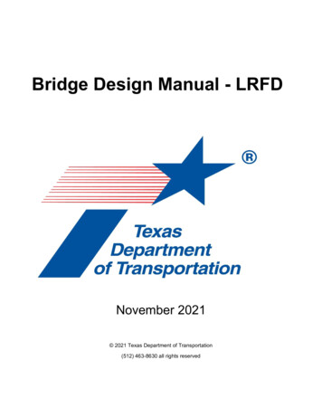
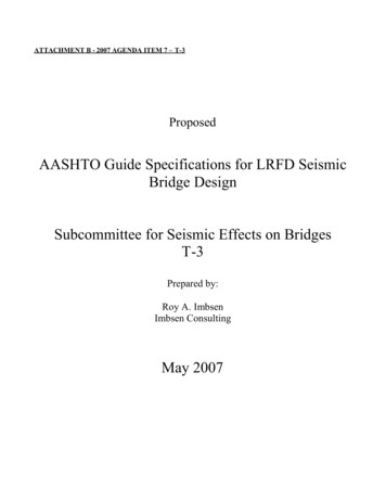
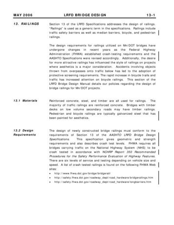
MAY 2006LRFD BRIDGE DESIGN13-2Crash testing requirements may be waived if the railing in question issimilar in geometrics to an approved crash tested rail and an analyticalevaluation shows the railing to be crash worthy. This allows minorchanges to crash tested railings without having to go through the timeand expense of crash testing.For bridges on the NHS any suchevaluation must be approved by the FHWA.Crash testing has shown that during impact vehicles slide along the top ofthe railing and parts of the vehicle, especially the boxes on trucks, extendbeyond the face of the railing a considerable distance. The envelope ofthe vehicle encroachment beyond the face of railing is known as the zoneof intrusion. Attachments to bridge railings, such as architectural metalrailings or objects just behind the railing (such as light poles), mustaddress safety concerns presented by this encroachment, which include:1) Snagging - which can cause the attachment or the vehicle hood topenetrate the occupant compartment.2) Spearing – objects, such as a horizontal railing member, penetratingwindshields and injuring occupants.3) Debris falling onto traffic below.A Midwest Roadside Safety Facility report, titled Guidelines forAttachment to Bridge Rails and Median Barriers, February 26, 2003,identifies zones of intrusion for several types of railings. Figure 13.2.1shows the zone of intrusion for a Test Level 4 barrier.Generally attachments within the zone of intrusion shall be designed tobreak away before severely damaging the vehicle, contain any debrisfrom damaging traffic below, and have no members (such as rail ends)that might spear the occupant compartment of the vehicle. Ends of railsshall be sloped at 45 degrees or less to top of barrier to reduce thechance of spearing. Posts shall be set back from the face of railing tominimize snagging.(See Sections 13.2.1 and 13.2.3 for setbackrequirements.)Railing designs shall include consideration of safety, cost, aesthetics andmaintenance. Safety shapes (Types J and F) were developed to minimizedamage to vehicles, as well as to contain and redirect vehicles back ontothe roadway, and have low initial and maintenance costs. Use of designsthat allow for easy replacement of damaged sections and use of standardrailings can minimize maintenance costs since replacement componentscan be stockpiled.Three general classes of bridge railings are Traffic Railings, Pedestrian orBicycle Railings, and Combination Railings. Bridge cross sections showing
MAY 2006LRFD BRIDGE DESIGN13-3these three classes are shown in Figure 13.2.2. Railing classes arefurther defined in the following sections. Also, refer to Table 13.2.1 forguidance on standard rail applications.1Figure 13.2.1Intrusion Zones for TL-4 BarriersReproduced from Keller, Sicking, Faller, Polivka & Rhode, Guidelines for Attachments to BridgeRails and Median Barriers, (Midwest Roadside Safety Facility, February 26, 2003), page 24.1
MAY 2006LRFD BRIDGE DESIGNFigure 13.2.213-4
RailTypeTrafficTL-4TL-4TL-4TL-4TL-4Solid Median Barrier (Type F, TL-4)5-397.130: w/ W.C.Split Median Barrier (Type F, TL-4)5-397.131: w/ W.C.Solid Median Barrier and Glare Screen (Type F, TL-4)5-397.132: w/ W.C.Split Median Barrier and Glare Screen (Type F, TL-4)5-397.135: w/o W.C.5-397.136: w/ W.COffset Split Median Barrier and Glare Screen (Type F,TL-4)5-397.137: w/ W.C.TL-5Concrete Barrier (Type F, TL-5) w/ Sidewalk5-397.125: Integral End Post w/ W.C.5-397.126: Integral End Post w/o W.C.TL-5TL-5Concrete Barrier (Type F, TL-5)5-397.122: Integral End Post w/ W.C.5-397.124: Integral End Post w/o W.C.Concrete Barrier (Type F, TL-5)5-397.128: Integral End Post w/ W.C.5-397.129: Integral End Post w/o W.CAllTL-4Concrete Barrier (Type F, TL-4)5-397.114: Separate End Post w/o W.C.5-397.115: Integral End Post w/o W.C.5-397.116: Separate End Post w/ W.C.5-397.117: Integral End Post w/ W.C.Traffic OnlyApplicationAllAllAllAllAllAllAllUse where roadways are atdifferent elevations. (Usually onsuperelevated bridges.)Traffic OnlyTraffic OnlyBridges with a longitudinal jointbetween roadways. (Usually thebridge is very wide or is to beconstructed in stages.)Traffic OnlyBridges with designated bike pathor where glare screen is required.Between sidewalk and roadwaywhere the shoulder is 6'. 40 mph High Protection Area whereDc 5 and Speed 40 mph.SpeedLimitTestLevelDescriptionTABLE 13.2.1: Standard Rail Applications4'-8" tall(Separation allows both sides to beslipformed.)4'-8" tall4'-8" tall2'-8" tall(For stage construction, each half ofbarrier meets TL-4 standard.)2'-8" tall4'-8" tall3'-6" tall(The additional height is to protecta bicycle rider from falling over therailing into traffic.)3'-6" tall(Gives added protection tomotorists on high speed, highcurvature roadways. Modifystandard to remove sidewalk.)2'-8" tallCommentMAY 2006LRFD BRIDGE DESIGN13-5
RailTypeTrafficCombination(Traffic and Ped./Bicycle)Traffic OnlyTraffic Only, where an aestheticrailing is desired.Application(cont.)YesYesTL-2Ped. &BikePed. &BikeConcrete Barrier (Type P-1, TL-2) and StructuralTube Railing with Fence (Design T-3)5-397.2125' Wire Fence (Design W-1) for Pedestrian Bridges5-397.2028' Wire Fence for Pedestrian Walks5-397.205Pedestrian bridges or sidewalksseparated from roadways by atraffic barrier.8' tall chain link fence5' tall chain link fence2'-4" parapet and 5'-8 ½" metal railwith chain link fabric 40 mph Highway bridges with walks. Thisrail is used on the outside edge ofwalk and meets bicycle andprotective screening requirements.Pedestrian bridges or sidewalksseparated from roadways by atraffic barrier.Top of metal railing 1'-10½" abovetop of 2'-8" Type F rail (Total heightof 4'-6" meets bicycle standard.)2'-4" parapet with 2'-2" metal rail(Modify for separate end post.)2'-4" parapet and 6' metal rail withchain link fabric.2'-8" tall1'-3" metal railing on 1'-9" parapet(Designer must modify detail forseparate end post or no W.C.)CommentAttachment to Type F rail for usewhere significant bicycle traffic willbe using roadway shoulder.AllTL-4 40 mph Outside edge of walk on highwaybridges with sidewalks wherebicycle traffic on the walk isexpected and protective screeningis not required. 40 mph Highway bridges with walks. Thisrail is used on the outside edge ofwalk and meets bicycle andprotective screening requirements.Structural Tube Railing (Design T-2)5-397.158TL-2Concrete Barrier (Type P-1, TL-2) and Wire Fence(Design W-1)5-397.119: Integral End Post5-397.120: Separate End PostAllTL-2TL-4Concrete Barrier (Type P-4, TL-4)5-397.173: Integral End Post w/ W.C.AllSpeedLimitConcrete Barrier (Type P-1, TL-2) and Metal Railingfor Bikeway (Type M-1)5-397.154: Integral End PostTL-4TestLevelConcrete Barrier (Type P-2, TL-4) and StructuralTube Railing (Type T-1)5-397.157: w/ Integral End PostDescriptionTABLE 13.2.1: Standard Rail ApplicationsNOTES: Crash testing levels refer to NCHRP Report 350. The structural tube traffic rail (Bridge Details Manual Part II, Fig. 5-397.157) and bicycle rail attachmentto Type F rail (Bridge Details Manual Part II, Fig. 5-397.158) were developed by Minnesota and crash tested through the pooled fund program.Combination railings with the 2'-4" parapet have been judged to meet crash Test Level 2 (TL-2) by comparison to other crash tested vertical face railings. Railing heights are measured to the finished surface (top of wearing course). Information on current costs of these railings may be obtained from the Bridge Estimating Unit. Combination railings may also be used as bicycle/pedestrian railings. The 2'-4" parapet height permits a wider spacing of spindles (6" openings ratherthan the 4" openings required up to 27" above the finished surface).Ped./BicycleMAY 2006LRFD BRIDGE DESIGN13-6
RailTypeCombination(Traffic and Ped./Bicycle)3'-9" metal rail on 2'-4" parapet(Developed by City of Minneapolisfor use on bridges in their city.)4'-6" metal rail on 2'-4" parapet(Bridge No. 23022 has a 2'-2"height of metal rail for use whereprotective screening is not needed.)3'-9" metal rail on 2'-4" parapet5'-8' to 9'-2" metal rail on 2'-4"parapet5'-51/2" metal rail on 2'-4" parapet(Sheet is metric.)5'-8" metal rail on 2'-4" parapetwith chain link fabric 40 mph Highway bridges with walks. Thisrail is used on the outside edge ofwalk and meets bicycle andprotective screening requirements. 40 mph Highway bridges with walks. Thisrail is used on the outside edge ofwalk and meets bicycle andprotective screening requirements. 40 mph Highway bridges with walks. Thisrail is used on the outside edge ofwalk and meets bicycle andprotective screening requirements. 40 mph Highway bridges with walks. Thisrail is used on the outside edge ofwalk and meets bicycle andprotective screening requirements. 40 mph Highway bridges with walks. Thisrail is used on the outside edge ofwalk and meets bicycle andprotective screening requirements. 40 mph Highway bridges with walks. Thisrail is used on the outside edge ofwalk and meets bicycle andprotective screening requirements.TL-2TL-2TL-2TL-2TL-2TL-2Concrete Barrier (Type P-3, TL-2) and OrnamentalMetal Railing (Type M-2)St. Peter RailingBridge No. 27R05TH 100 Corridor StandardBridge No. 27285TH 212 Corridor StandardBridge No. 27148TH 610 Corridor StandardOrnamental Metal Railing Type DWGBridge No. 27222Victoria Street RailingBridge No. 62823Comment2'-2 3/4" metal rail on 2'-4" parapet(Sheet is metric.)Application 40 mph Outside edge of walk on highwaybridges with sidewalks wherebicycle traffic on the walk isexpected and protective screeningis not required.SpeedLimitTL-2TestLevelCloquet RailingBridge No. 09008 and 09009DescriptionTABLE 13.2.2: Non-Standard Rail ApplicationsMAY 2006LRFD BRIDGE DESIGN13-7
RailTypeSt. Peter RailBridge No. 40002Lexington RailBridge No. 62823Gooseberry Falls Suspended Walkway RailBridge No. 38010DescriptionPed. &BikePed. &BikePed.TestLevelN/AN/AN/ASpeedLimitPedestrian bridges or sidewalksseparated from roadways by atraffic barrier.Pedestrian bridges or sidewalksseparated from roadways by atraffic barrier.Pedestrian bridges or sidewalksseparated from roadways by atraffic barrier.Application(cont.)4'-6" tall (Sheet is metric.)4'-6" tall (Sheet is metric.)3'-6" tall (Sheet is metric.)CommentNOTES: Crash testing levels refer to NCHRP Report 350. Combination railings with the 2'-4" parapet have been judged to meet crash Test Level 2 (TL-2) bycomparison to other crash tested vertical face railings. Railing heights are measured to the finished surface (top of wearing course). Information on current costs of these railings may be obtained from the Bridge Estimating Unit. Combination railings may also be used as pedestrian/ bicycle railings. The 2'-4" parapet height permits a wider spacing of spindles (6" openings ratherthan the 4", which is required in the lower 27").Pedestrian/BicycleTABLE 13.2.2: Non-Standard Rail ApplicationsMAY 2006LRFD BRIDGE DESIGN13-8
MAY 200613.2.1 TrafficRailingLRFD BRIDGE DESIGN13-9Traffic railings are designed to contain and safely redirect vehicles.Requirements based on speed are as follows.1) High Speed Roadways with a Design Speed 40 mphMn/DOT requires crash testing to Test Level 4 as the minimumstandard for these roadways. Test Level 4 is run with a small car anda pickup truck at 60 mph and a single unit van truck impacting at 50mph. This railing will normally be the 32" high Type F barrier (BridgeDetails Manual Part II, Figure 5-397.114-117). Where aestheticneeds warrant, the tubular traffic railing (Bridge Details Manual PartII, Figure 5-397.157) is an acceptable alternative that provides anincreased viewing opportunity to drivers crossing the bridge. Itconsists of a structural tube and posts mounted to the top of a 1'-9"high concrete base. Note, however, that the tubular traffic railing hashigher initial and maintenance costs than the Type F barrier. Consultthe Preliminary Bridge Unit for additional acceptable railings.Mn/DOT has developed a bicycle railing attachment to the Type Fbarrier for use where the bridge shoulders carry a bicycle route asdefined in the Mn/DOT State Bicycle Transportation System Plan oranother recognized authority. This attachment (Bridge Details ManualPart II, Figure 5-397.158) adds height to the railing to protect bicycleriders and has been crash tested to Test Level 4. It has a cablesystem inside the rail tubes that will contain the rail pieces in theevent of an accident. It also uses weakened posts designed to lessenthe impact to vehicles in the event of a hit. This railing may beapplied to other traffic barriers provided that the same or greateroffset distance to the face of metal rail is provided and the postattachment has the same or greater strength. The cable system mustbe maintained even if there is no traffic below as the cables act tokeep the entire rail system intact during a crash.The zone of intrusion (see Section 13.2 for definition) shall be keptfree of rail attachments or other features unless they have been crashtested or an analytical evaluation has shown them to be crash worthy.Exceptions to this policy include noise walls and safety features suchas signs or lights. Note that light poles shall be located behind theback of the barrier. When noise walls are attached, consider using ahigher Type F barrier to lessen the risk. The zone of intrusion for aTL-4 railing is shown in Figure 13.2.1.A more stringent rail design may be considered on abasis for bridges with high design speeds, high truckcurvature or other site-specific safety considerations.Test Level 5 railing should be considered for these sites.case-by-casevolume, andGenerally aTest Level 5
MAY 2006LRFD BRIDGE DESIGN13-10includes a small car and a pickup truck traveling at 60 mph plus avan-type tractor trailer impacting at 50 mph. As a guide, a 42" highType F barrier that meets TL-5 requirements is recommended forbridges having a horizontal curvature of 5 degrees and sharper on aroadway where the design speed is 45 mph or higher.ThePreliminary Bridge Plans Engineer will designate the rail design on thePreliminary Bridge Plan.2) Low Speed Roadways with a Design Speed 40 mphMn/DOT requires crash testing to Test Level 2 as the minimumstandard for these roadways. Test Level 2 is run with a small car andpickup truck both impacting at a speed of 45 mph.Normally these railings will be the same as used for higher speeds,usually the Type F concrete barrier, but with the reduced levelrequired for crash testing more options are available. Consult thePreliminary Bridge Unit for additional acceptable railings.If the addition of an ornamental metal railing is desired on the top ofthe traffic railing, a 32" high vertical faced concrete barrier (seeBridge Details Manual Part II, Figure 5-397.173) shall be used ratherthan the Type F barrier. The vertical face will cause more damage toa vehicle for minor hits but reduces the tendency for the vehicle toclimb the face or roll over and will keep the vehicle back from themetal rail. A small 2" wide by 6" high curb is provided at the base tominimize snowplow damage to the barrier. For design speeds of35 mph and below a metal railing may be used on the top of theconcrete barrier with no minimum offset required, as it is unlikely thatvehicles will contact the metal portion.2 With a design speed of 40mph the front face of the metal railing shall be offset a minimum of 9"from the face of barrier at the top of concrete.3It is strongly recommended that a smooth face be used on the highwayside of concrete barriers. Aesthetic treatments on the highway faceincrease the risk of vehicle snagging. In addition, in this environment theaesthetics treatment will routinely experience vehicle hits, snowplowscrapes, and high exposure to salt. As a result, their performance will begreatly reduced, causing increased maintenance costs.2Reproduced from Keller, Sicking, Faller, Polivka & Rhode, Guidelines for Attachments to BridgeRails and Median Barriers, (Report dated February 26, 2003), pages 3 and 27.3Reproduced from Keller, Sicking, Faller, Polivka & Rhode, Guidelines for Attachments to BridgeRails and Median Barriers, (Report dated February 26, 2003), page 15 and 16. 9" offset at40 mph judged acceptable based on 12" offset at 45 mph.
MAY 200613.2.2 Pedestrian/Bicycle RailingLRFD BRIDGE DESIGN13-11Pedestrian or bicycle railings are generally located at the outside edge ofa bridge sidewalk and are designed to safely contain pedestrians orbicyclists. AASHTO specifications require pedestrian railings to be atleast 3'-6" in height and bicycle railings to be at least 4'-6" in height.The height is measured from the top of walkway to top of the highesthorizontal rail component.Openings between members of a pedestrian railing shall not allow a 4"sphere to pass through the lower 27" of the railing and a 6" sphereshould not pass through any openings above 27". This is more restrictivethan AASHTO and is intended to prevent small children from slippingthrough the railing.The International Building Code requires a 4"maximum opening.13.2.3CombinationRailingCombination railings are dual purpose railings designed to contain bothvehicles and pedestrians or bicycles. These railings are generally locatedat the outside edge of a bridge sidewalk. A raised sidewalk is used toclearly define the walkway area and keep roadway drainage off thewalkway. The sidewalk curb offers some protection to pedestrians fromerrant vehicles entering the walkway. There is no other barrier betweenthe roadway and the sidewalk. Combination railings are applicable fordesign speeds of 40 mph and under. Mn/DOT requires crash testing toTest Level 2 for these railings and the strength and geometricsrequirements for bicycle or pedestrian railings also apply.Combination railings will normally consist of a 2'-4" high concrete parapetwith a fence or ornamental metal railing mounted on the top. Theconcrete parapet serves to contain traffic and has been judged to meetcrash Test Level 2. The metal railing must comply with the strength andgeometric requirements for bicycle or pedestrian railings. A non-crashtested metal railing may be used on the top of the concrete barrier, as itis unlikely that vehicles will make contact with the metal portion.For typical applications, the highway face of a concrete parapet shall berelatively smooth for ease of construction (slipforming) and maintenance.Where aesthetic needs warrant it, beveled recesses up to 2" deep may beallowed for inset panels and beveled form liner textures. Concrete postsabove the parapet are acceptable but they may not project in front of theparapet.For design speeds greater than 40 mph, a traffic railing is requiredbetween the roadway and sidewalk or bikeway. Use a 32" high Type Fbarrier for the traffic railing when the shoulder is 6'-0" or greater inwidth. If the roadway shoulder is less than 6'-0", use a 42" Type F
MAY 2006LRFD BRIDGE DESIGN13-12barrier for added protection. Metal railings shall not be placed on top of atraffic railing between a sidewalk and a roadway. Although metal railingsmay somewhat increase protection for bicyclists, they are a risk hazard tovehicles.13.2.4 Strength ofStandard ConcreteBarriersBarrier resistance values have been determined for the standard Mn/DOTconcrete barriers and are shown in Table 13.2.4.1. They are based onusing both near and far face reinforcement as tension reinforcement.These values can be used when analyzing deck overhangs to determinereinforcement requirements.(See Section 9.2.4J for an overhangreinforcement design example.)
4.64.69.39.29.39.29.39.24.54.14.2Concrete Barrier (Type F, TL-4)5-397.116: Separate End Post w/ W.C.5-397.117: Integral End Post w/ W.C.Concrete Barrier (Type F, TL-5)5-397.122: Integral End Post w/ W.C.Concrete Barrier (Type F, TL-5)5-397.124: Integral End Post w/o W.C.Concrete Barrier (Type F, TL-5) w/ Sidewalk5-397.125: Integral End Post w/ W.C.Concrete Barrier (Type F, TL-5) w/Sidewalk5-397.126: Integral End Post w/o W.C.Concrete Barrier and Glare Screen (Type F, TL-5)5-397.128: Integral End Post w/W.C.Concrete Barrier and Glare Screen (Type F, TL-5)5-397.129: Integral End Post w/o W.C.Split Median Barrier (Type F, TL-4)5-397.131: w/ W.C.Split Median Barrier and Glare Screen (Type F, TL-4)5-397.135: w/o W.C.Split Median Barrier and Glare Screen (Type F, TL-4)5-397.136: w/ W.C.Lc(ft)Concrete Barrier (Type F, TL-4)5-397.114: Separate End Post w/o W.C.5-397.115: Integral End Post w/o W.C.DescriptionEnd 259.2Rw(kips)TABLE 13.2.4.1: Resistance Values for Standard Concrete 22.9124.1Rw(kips)Interior PanelMAY 2006LRFD BRIDGE DESIGN13-13
Concrete Barrier (Type P-1, TL-2)5-397.1195-397.1205-397.1545-397.212Concrete Barrier (Type P-4, TL-4)5-397.173: Integral End Post w/ W.C.Concrete Barrier (Type P-2, TL-4)5-397.157: w/ Integral End PostOffset Split Median Barrier and Glare Screen (Type F, TL-4)5-397.137: w/ W.C.Description4.94.64.64.2Lc(ft)End Panel50.476.887.761.1Rw(kips)TABLE 13.2.4.1: Resistance Values for Standard Concrete ips)Interior PanelMAY 2006LRFD BRIDGE DESIGN13-14
MAY 200613.2.5 ProtectiveScreeningLRFD BRIDGE DESIGN13-15The addition of protective screening to bridge railings is a further Mn/DOTpolicy requirement.The practice of adding protective screening iscommon nationwide in response to accidents and fatalities that haveoccurred due to pedestrians throwing objects from overpasses ontovehicles below.Protective screening must be included in the design of new bridges thataccommodate pedestrians when the bridge crosses a roadway or railroad,and also when railings are replaced on existing bridges as follows: On bridges where a sidewalk is included in the design, incorporate aprotective screening system in the design of the railing adjacent tothe sidewalk. On pedestrian bridges, place the protective screening on both sides ofthe bridge.The protective screening system will be, preferably, a chain link fencesystem or a railing system. The height of the fence or railing shall be8'-0" above the top of the sidewalk. For sites with special aesthetictreatments involving ornamental railings a minimum height of 6'-0" willbe allowed. However, it should be recognized that the lower railingheight provides a reduced level of protection. The protective screeningsystem shall not allow objects 6" or greater in diameter to pass throughthe fence or railing.13.2.6Architectural/OrnamentalRailingsIn response to local requests, special railing designs have beenincorporated in some projects to address aesthetic concerns. Theseornamental architectural bridge railings have been utilized in lieu ofstandard combination railings for placement on the outboard side ofbridge sidewalks. The Bridge Office will consider railing designs inaddition to our standard railings for such locations and corridors. It isrecommended that special railings incorporate features from the standardrailings (such as connection details) as significant effort has gone into thedevelopment of these details.Mn/DOT participation in the cost of aesthetic railings is governed by theMn/DOT Policy Manual of June 2001. Refer to these documents for moreinformation: Guidelines: Mn/DOT Policy and Procedures for CooperativeConstruction Projects with Local Units of Government Position Statement: Mn/DOT Policy and Procedures for CooperativeConstruction Projects with Local Units of Government
MAY 2006LRFD BRIDGE DESIGN13-16Railings are included with other aesthetic costs of the bridge. Mn/DOTparticipation is limited to 5%, 7% or 15% of the cost of a basic bridge,depending on the aesthetic level of the bridge.Cost participation of architectural/ornamental railings on local bridges isgenerally funded up to the prorated cost of standard railing or chain linkfence. Consult the State-Aid for Local Transportation Office for conditionson bridge funding eligibility.13.3 DesignExamplesTwo design examples follow. The first illustrates the design proceduresassociated with a conventional Type F barrier.The second designexample illustrates the steps undertaken for the design of adhesiveanchors to support a metal railing.
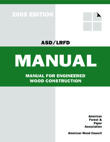
MAY 2006LRFD BRIDGE DESIGN13-1713.3.1 Type FBarrier DesignExampleThis example illustrates a design check of the vertical reinforcing steelthat ties a standard Mn/DOT Type F barrier to a concrete deck. Thegeometry of the barrier and the reinforcing bar sizes and types areillustrated in Bridge Details Part II Fig. 5-397.117. The configuration ofthe horizontal reinforcing bars in the railing is assumed fixed. Thespacing of the vertical reinforcing steel is checked to ensure adequatecapacity is provided. The design check uses the method described inLRFD Article A13.3.1.A. Design Forcesand DimensionsMn/DOT’s Type F barrier satisfies the geometric height constraint of aTL-4 barrier and has satisfactorily passed crash testing to such a level.The design forces and dimensional limits for a TL-4 barrier presented inLRFD Table A13.2-1 are repeated below.[13.7.3.2]Design Forces and DesignationsTL-4 BarrierFt Transverse (kip)54FL Longitudinal (kip)18FV Vertical/Down (kip)18L t and LL (ft)3.5L V (ft)18He Minimum Height of Horizontal Loads (in)32H Minimum Height of Rail (in)32The designvariables: Mb – the Mw – the Mc – theis based on yield line analysis methods and has threeflexural capacity of the cap beam (if present)flexural capacity of the railing about its vertical axisflexural capacity of the railing about a horizontal axisLRFD Article 13.1 cautions designers that railings placed on retainingwalls or spread footings may require investigation beyond that presentedin this example. The governing or controlling yield line mechanism isassumed to form in the railing. If additional mechanisms with potentiallylower load capacities are possible, designers should investigate them.The yield line mechanisms vary with rail location. Interior rail regions areassumed to have three yield lines. Two of the yield lines have tension onthe inside of the railing and one has tension on the outside of the railing.See Figure 13.3.1.1, reproduced from LRFD Figure CA13.3.1-1.The assumed failure mechanism at the end of rail sections (neardeflection joints, expansion joints, openings, etc.) has one yield line thatproduces tension on the inside face of the railing. See Figure 13.3.1.2,reproduced from LRFD Figure CA13.3.1-2.
MAY 2006LRFD BRIDGE DESIGNFigure 13.3.1.1Yield Line Analysis for Interior RegionFigure 13.3.1.2Yield Line Analysis for End Region13-18
MAY 2006LRFD BRIDGE DESIGN13-19Figure 13.3.1.3 contains a rail elevation detail that identifies the locationof interior and end regions. The length of end regions and interiorregions is dependent on the relative flexural capacities of the railing ( Mwand Mc ). The design example uses L ce to represent the length of endregions and L ci to represent the length of interior yield line mechanisms.Holding Mw constant, rail sections with larger Mc resistances haveshorter and steeper yield line mechanisms.Designers should note that in addition to inclined yield lines, one-waycantilever resistance of the rail should be investigated for rail segmentswith lengths less than twice L ce .B. Barrier FlexuralResistanceThree section details of a Type F barrier are presented in Figure 13.3.1.4.The top section presents typical reinforcement and geometry.Thehorizontal reinforcement consists of eight #13 bars. Two #16 bars areused for the vertical reinforcement. The R1601E bar is anchored in thedeck and projects 10" into the rail. The R1602E bar is a closed stirrupthat laps the R1601E bar.The center detail in Fig
MAY 2006 LRFD BRIDGE DESIGN 13-7 Comment 2'-2 3 / 4" metal rail on 2'-4" parapet (Sheet is metric.) 3'-9" metal rail on 2'-4" parapet (Developed by City of Minneapolis for use on bridges in their city.) 4'-6" metal rail on 2'-4" parapet (Bridge No. 23022 has a 2'-2" height of metal rail for use where protective screening is not needed.) 3'-9" metal rail on 2'-4" parapet 5'-8' to 9'-2" metal .