Transcription
JFE TECHNICAL REPORTNo. 19 (Mar. 2014)“HBL‡385 Series,” 550 N/mm2 Class Steelfor Building Structureswith Good Balance of Excellent Earthquake Resistanceand Economic Efficiency†NAKAGAWA Kei*1UEKI Takuya*2NANBA Takayuki*3Abstract:Since the initial approval for “HBL TM 385,”550 N/mm2 class steel plate for building structure by theMinister of Land, Infrastructure, Transport and Tourismin 2002, JFE Steel has developed 550 N/mm2 classbuilding materials and products, such as circular steeltube and cold-press-formed square steel tube, as a pioneer in the industry. This paper explains the outline of“HBLTM385 series” including its excellent mechanicalproperties as a building material and economic advantadge, and provides some findings about its structuraldesign and fire-resistant design.1. IntroductionJFE Steel’s HBLTM385 Series1–4) realize a low yieldratio and high toughness, while also being a highstrength steel with tensile strength of 550 N/mm2 orhigher (yield strength: 385 N/mm2 or higher), by use ofthe on-line accelerated cooling system Super-OLACTM,which is an advanced “number one” technology of JFESteel. Taking advantage of these features, high seismicsafety can be secured by appropriate design and construction. Adoption of a composition design that considers weldability also enables preheating control in welding on the same level as with 490 N/mm2 class steels.Because high economic efficiency can be obtained bythe reducing the weight of the steel used in structures,†‡Originally published in JFE GIHO No. 31 (Jan. 2013), p. 8–15“HBL” is registered trademark in Japan.*1Senior Researcher Deputy Manager,Civil Engineering Res. Dept.,Steel Res. Lab.,JFE Steelwhich is possible because of the high strength of thissteel, and lightening welding control and shorteningwelding time thanks to its excellent weldability, theHBLTM385 Series offers the highest economic efficiencyper unit of strength of steel materials of any steel forbuilding structures (comparison with JFE Steel’s products). The HBLTM385 Series has earned a high evaluation for this advantage, and has been widely adopted,particularly in high-rise buildings. (As of July 2012,cumulative use had reached 95 000 tons.) In 2010,HBLTM385 Series received the Contribution Award ofthe 42nd Ichimura Prizes in Industry.JFE Steel has also developed use technologies relatedto the design and construction of the HBLTM385 Series,such as structural performance evaluation5–9) for composite structures, i.e., concrete filled steel tubular structures (CFT structures) and steel reinforced concretestructures (SRC structures), fire resistance performanceevaluation10), etc. which have become increasinglyimportant in recent years.This paper presents an outline of the HBLTM385Series and its structural performance and fire resistanceperformance.2. Outline of HBLTM385 SeriesThe standards of the chemical composition andmechanical properties of the HBLTM385 Series are*2Senior Researcher Deputy Manager,Civil Engineering Res. Dept.,Steel Res. Lab.,JFE Steel*3Senior Researcher Manager,Civil Engineering Res. Dept.,Steel Res. Lab.,JFE Steel1
“HBL385 Series,” 550 N/mm2 Class Steel for Building Structures with Good Balance of Excellent Earthquake Resistance and Economic EfficiencyTable 1ProductsPlatesDesignationThickness(mm)HBL385B-L12 t sG385TCSi50 t 100Mn0.0300.200.550.02019 t 5019 t 500.0300.200.550.551.600.200.551.6019 t 20.00650 t 00.005fHAZ0.290.0081.60PCM0.40—50 t 100Ceq0.440.0151.6019 t 5050 t 100(mass%)Chemical compositionsPSN*19 t 50G385BG385CChemical compositions of HBLTM385 Series—0.58N*: Total nitrogenCarbon equivalent: Ceq C Mn/6 Si/24 Ni/40 Cr/5 Mo/4 V/14Weld crack sensitivity composition: PCM C Si/30 Mn/20 Cu/20 Ni/60 Cr/20 Mo/15 V/10 5BHeat affected zone (HAZ) toughness estimation parameter for metal active gas welding (MAG welding): fHAZ C Mn/8 6(P S) 12N-4Ti (Ifthe chemical composition of Ti 0.005%, it is regarded as zero.)Table P-385C385-535(19 5550-670Mechanical properties of HBLTM385 seriesTypicalspecimenThickness(mm)El (%)JIS 1At 3815JIS 5t 5026JIS 440 t20JIS 12AJIS 12BJIS 419 t 401940 t 10021JIS 1A19 t 3215JIS 432 t 5020JIS 1A19 t 3215JIS 432 t 5020YR (%)80vE0ºC(J)70RA (%)―25*1(15*2)857070*38070*4―25*1(15*2)―*125 (15*2)―*125 (15*2)YS: Yield strength TS: Tensile strength El: Elongation YR: Yield ratio vE0ºC: Charpy absorbed energy at 0ºC*1Average *2Each *3Flat part *4Flat part and corner partRA: Reduction of area in through thickness tensile testshown in Table 1 and Table 2, respectively.As mentioned above, while the products in theHBLTM385 Series are high-strength steels with tensilestrength of 550 N/mm2 or higher, excellent weldabilityis also secured by providing a carbon equivalent, Ceq,and weld crack sensitivity composition, PCM, equal to orlower than those of the 490 N/mm2 class steel SN490. Incircular steel tubes (P-385) and cold-press-formedsquare steel tubes (G385, G385T), securing the toughness of the heat affected zone (HAZ) is also consideredby providing the metal active gas welding (MAG welding) HAZ toughness index fHAZ11). At the same time, inthese steel tubes, consideration is also given to prevention of strain age hardening due to cold working of thebase metal by specifying total nitrogen N* of 0.006% orless. Moreover, from the viewpoint of seismic safety,2HBLTM385 plates satisfy both a low yield ratio (80% orless) and high Charpy absorbed energy (70 J or higher at0 C), and other HBLTM385 Series products also possessmechanical properties conforming to those of plates.HBLTM385 plates, circular steel tubes, and coldpress-formed square steel tubes are each available in theB type, assuming application to principal building members or welded members, and the C type, which assumesapplication to members in which thickness directionproperties are also required. The C type equivalent ofG385T is called G385-Z25. With both the C type andG385-Z25, a reduction of area (RA) provision is addedin thickness direction properties tests.Among HBLTM385 plates, HBLTM385-E is availableas a specification supporting large heat input welding,mainly for welded square box-section columns2).JFE TECHNICAL REPORT No. 19 (Mar. 2014)
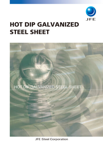
“HBL385 Series,” 550 N/mm2 Class Steel for Building Structures with Good Balance of Excellent Earthquake Resistance and Economic EfficiencyThe features of the 550 N/mm2 class cold-pressformed square steel tube G385 and the 550 N/mm2 classhigh performance cold-press-formed square steel tubeG385T are discussed in Section 3.2, together with theirstructural performance.3. Structural Performance3.1 Structural Performanceagainst Local BucklingThe 1980 notification of the Ministry of ConstructionNo. 1791, Article 2 and notification No. 1792, Articles 1and 3, as revised in 2007, provided width-thicknessratios for carbon steel with specified design strength205–375 N/mm 2. 12) However, the treatment of theHBLTM385 Series was not clarified since its specifieddesign strength is 385 N/mm2. Therefore, in order tostudy the width-thickness ratio rank of the HBLTM385Series, structural performance against local bucklingwas investigated with the respective cross sections,namely, (1) welded built-up box section, (2) weldedbuilt-up H section (BH section), (3) circular tube section, and (4) cold-press-formed square tube section, byperforming a stub column compression test using thewidth-thickness ratio as a parameter.Figure 1 shows an outline of the test. In accordancewith the literature13), monotonous loading in the verticaldirection was performed so as to apply loading uniformly to the cross section.Table 3 (a)–(d) show the section sizes of each specimen and the calculated yield load. With sections (1), (3),and (4), the height h of the specimens was planned as 3times the diameter D, and with section (2), h was 2.5times the width B.The calculated yield load Ny of the specimens wasobtained by multiplying the cross-sectional area A calculated from the actual measured values by the yieldstrength σy in a tensile test of the steel used in the specimen.Figure 2 (a)–(d) show the plastic deformation magnification R obtained in the experiment with the resultsfor other steel grades14–19). Plastic deformation magnification R is obtained by subtracting 1 from the ductilityfactor μ and is defined by the following equation.R μ 1, μ εmax/εyεmax : Compressive strain at maximum proofstress (load capacity) in experiment(Shrinkage of specimen/Initial height)εy : Yield strain (σy/E)σy : Yield strength of steel material used in specimen in tensile test (N/mm2)JFE TECHNICAL REPORT No. 19 (Mar. 2014)Fig. 1Table 3Overview of stub-column testSection size and calculated yield load(a) Stub-column of box 1.726.492913 9005 640BOX-FBC346.312.028.91 04116 1006 520BOX-FCD374.910.037.51 12614 6005 850(b) Stub-column of BH sectionBH-FAHBtwtfb/tf(mm) (mm) (mm) (mm)d/twhANy(mm) (mm2) (kN)464.2 281.7 19.319.27.322.1692 19 000 8 660BH-FAB 444.1 282.1 11.919.37.334.1692 15 700 6 910BH-FBC 436.7 327.1 19.219.38.520.7801 20 300 9 220(c) Stub-column of circular tube sectionD(mm)t(mm)D/th(mm)A(mm2)Ny(kN)8 370P-FC599.411.751.51 80021 500P-FBC629.415.640.31 89030 100 11 60034 000 13 100P-FAB599.118.732.11 800P-FA12268.511.623.28109 3504 050P-FA19426.918.622.91 28423 9009 630(d) Stub-column of square tube sectionDt(mm) (mm)D/trh(mm) (mm)A(mm2)G-FA-1349.719.318.168.81 050 23 600 10 300G-FA-2350.519.218.370.01 050 23 500 10 100G-FAB-1 449.819.323.468.71 351 31 200 13 800Ny(kN)D: Width of cross-sectiont: Thickness of cross-sectionH: Height of BH sectionB: Width of BH sectiontw: Web thickness of BH section tf: Flange thickness of BH sectionh: Hight of stub-columnb B/2d H 2tfr: Outer diameter of corner of square tube sectionA: Cross-sectional areaNy: Calculated yield load3
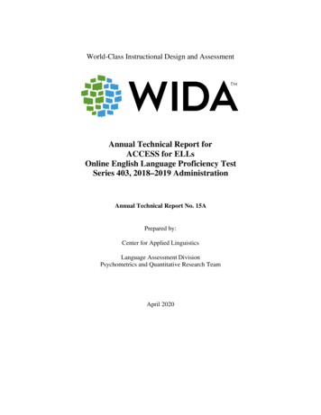
“HBL385 Series,” 550 N/mm2 Class Steel for Building Structures with Good Balance of Excellent Earthquake Resistance and Economic Efficiency(a) Box section(b) BH section(c) Circular tube sectionFig. 2(d) Square tube sectionResults of stub-column test (Plastic deformation magnification)E : Young’s modulus ( 205 000 N/mm2)In Fig. 2, specimens of different strength classes arecompared by arranging the specimens by the equivalentwidth-thickness ratio, which is obtained by multiplying(σy/E)1/2 by the width-thickness ratio D/t (in case of thecircular tube section, by multiplying σy/E by the diameterthickness ratio D/t). With all the sections, the HBLTM385Series have plastic deformation magnification similar tothat of the existing 400 N/mm2 to 590 N/mm2 classsteels, and also achieves the plastic deformation magnification for the width-thickness ratio rank corresponding(with necessary modifications) to that in the abovementioned Ministerial notifications. As the target valuesof plastic deformation magnification, the values herewere “4 for FA (P-I-1), 2 for FB (P-I-2), and 0 for FC(P-II),” which are established by width-thickness ratiorank, in “Recommendations for Limit State Design ofSteel Structures20).”In addition to the results of the stub-column testdescribed above, bending experiments with a weldedbuilt-up box section and the beam of a welded built-upBH section confirmed that HBLTM385 has structural performance on the same level as SN490, etc. in terms ofbuckling resistance performance, clarifying the appropriateness of corresponding application of the above4mentioned notifications when setting width-thicknessratios. A lateral buckling test was also performed21) toexamine the spacing of stiffening to prevent lateralbuckling of the beam in BH sections, and design equations were then constructed based on the viewpoint invarious recommendations and standards.After organizing this various knowledge, JFE Steelobtained a Performance Evaluation (BCJ EvaluationST0179-03) of the design provisions for the HBLTM385Series from the Building Center of Japan.3.2 Structural Performance ofHigh Performance Cold-Press-FormedSquare Steel Tube G385TJFE Steel and Seikei Steel Column Corp. commercialized a jointly-developed 550 N/mm2 class coldpress-formed square steel tube for building structuraluse, G385, in 2004 and also commercialized a high performance 550 N/mm2 class cold-press-formed squaresteel tube for building structural use, G385T, in 2012.As shown in Tables 1 and 2, in G385T, toughness of70 J or higher is specified not only in the flat parts of thecross section, but also in the corner parts. In the chemical composition, the contents of P and S, which reducethe toughness of the base material, are limited to lowerlevels than in G385, and consideration is also given toJFE TECHNICAL REPORT No. 19 (Mar. 2014)
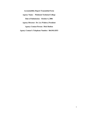
“HBL385 Series,” 550 N/mm2 Class Steel for Building Structures with Good Balance of Excellent Earthquake Resistance and Economic EfficiencyFig. 3Overview of G385T bending testTable 4Bending specimens of G385TD(mm)t(mm)D/tr(mm)LD( )Mp(kN · m)qp(rad)T14501923.766.5451 9930.011 4T25003215.6112453 7860.010 6T35003215.6112453 7290.010 5T44003212.5112452 2880.013 8T55003215.611204 1940.011 8T65003215.6112454 0450.011 4T76003218.8112456 1150.009 3D: Width of cross-section t: Thickness of cross-sectionr: Outer diameter of corner of square tube sectionLD: Loading directionMp: Calculated full plastic momentq p: Calculated rotation angle at Mpsecuring the toughness of the heat affected zone morestrictly, by limiting the MAG welding HAZ toughnessindex fHAZ to a low level.Figure 3 shows an overview of the G385T bendingtest. The specimen was prepared by welding 2 throughdiaphragms in the central loading part of a G385T steeltube, and a 3-point bending test was performed by gradually increased cyclic loading under peak-to-peak alternate incremental loading with the two ends as pin supports.Table 4 shows the list of bending test specimens. Thewidth-thickness ratio, D/t, of the cross-section of thecolumn and the loading direction (0 , 45 ) were used asparameters. The same conditions were applied withspecimens T2, T3, and T6 in order to examine the variation in results when using multiple specimens. TheNBFWTM welding method was applied with all specimens (NBFW: Non-Brittle Fracture Welding). NBFWTMis a construction method in which brittle fracture isavoided by welding a through diaphragm in the column19, 22).Figure 4 shows the results of the bending test ofG385T. The cumulative plastic deformation ratio (cumuJFE TECHNICAL REPORT No. 19 (Mar. 2014)Fig. 4Result of G385T bending testlative ductility) η, which is an index of seismic safety, isshown on the vertical axis. The cumulative plastic deformation ratio, η is calculated by the following equation13).η ΣW / (Mp·θp)ΣW : Energy absorbed by plastic hinge of specimen (kJ)Mp : Full plastic moment of column (kN·m)θp : Angle of rotation at full plastic moment ofcolumn (rad)The horizontal axis in Fig. 4 shows the width-thicknessratio, D/t, arranged by the equivalent width-thicknessratio, α, in which D/t is standardized by the yieldstrength, σy, obtained in a tensile test of the skin plate ofthe flat part of the column.Because the strength of specimen T1 decreased dueto local buckling, the data for that specimen werearranged with the point in time when strength (proofstress) decreased 5% from maximum strength as theultimate state. In all the other specimens, ductile fractures which initiated from the toe of the diaphragm weldbead grew to the column base metal side and fractureoccurred after large plastic deformation. This is theassumed fracture mode in the NBFWTM method, namely,“Prevention of fracture in the weld (HAZ) enables thebase metal of the steel tube to demonstrate its performance to the maximum extent.”Based on various studies, including the contentdescribed above, a design method evaluation (BCJ Evaluation ST0205-01) was received from The BuildingCenter of Japan, allowing omission of supplementary5
“HBL385 Series,” 550 N/mm2 Class Steel for Building Structures with Good Balance of Excellent Earthquake Resistance and Economic Efficiencydesign items such as the strength decrease required inBCP325, etc. (2007 notification of the Ministry of Land,Infrastructure, Transport and Tourism No. 594, Article4.3, b, 2 and specification provisions provided in the1980 notification of the Ministry of ConstructionNo. 1791, Article 2.3, a) by applying the NBFWTMmethod to the 550 N/mm2 class cold-press-formedsquare steel tube for building structural use, G385T.3.3 Structural Performance as CompositeStructuresConcrete filled steel tubes (hereinafter, CFT) havethe advantage that excellent deformation performanceand fire resistance performance can be obtained by aneffect in which the steel tube confines the concrete (confinement effect) while the concrete provides bucklingstiffening for the steel tube. Concrete filled steel tubeshave been applied widely in recent years, centering onhigh-rise buildings.Figure 5 shows an overview of the shear bendingtest under constant axial force of a CFT column usingG3857). The specified compressive force is applied to theCFT column specimen by an oil hydraulic jack attachedin the vertical (axial) direction, and shear bending isthen applied cyclically by peak-to-peak alternate loadingby a second jack attached in the horizontal direction.Table 5 shows the list of CFT specimens. The compression strength of the concrete filling is approximately60 N/mm2. The concrete is placed by the direct castingmethod. The experimental parameters were the widththickness ratio (D/t) of the steel tube and the axial forceratio (n N/N0, N: Vertical axial force, N0: Compressivestrength at center). Figure 6 shows an example of thebending moment (M)-story drift (θ SD) relationshipobtained from this experiment in the case of specimenG3. Here, the influence of the P-Δ effect is considered inthe evaluation of the bending moment in the experiment.Strength did not decrease suddenly under the cyclicincremental loading, and the original axial strength wasFig. 5 Overview of shear bending test under constant axial force6maintained until the end of loading.Figure 7 shows the result of the shearing bendingtest under constant axial force. At each width-thicknessratio, the experimental maximum bending moment(testMu) was divided by the value (anhMu) calculated by anevaluation formula in the literature23). As all the plotsare positioned near 1 on the vertical axis, it can beunderstood that the maximum bending moment of CFTcolumns using G385 generally corresponds to that givenby the evaluation formula in the literature23). For comparison, the results of past research9, 24) were also plottedin Fig. 7. The results of the CFT columns using G385Table 5Specimens of CFTDtnS syS suSYRCs BD/t(mm) (mm)(N/mm2) (N/mm2) (%) (N/mm2) ( N/N0)G1 35012 29.2G2 35012 29.2G3 45012 37.53955427363.80.465.90.668.10.4D: Width of cross-section t: Thickness of cross-sectionYield strength of steel Ssu: Tensile strength of steelSYR: Yield ratio of steelCsB: Compression strength of concreten: Axial force ratio N: Axial forceN0: Compressive strength at the centerS sy :Fig. 6 Bending moment–story drift relationship (Specimen G3)Fig. 7 Result of shear bending test under constant axial forceJFE TECHNICAL REPORT No. 19 (Mar. 2014)
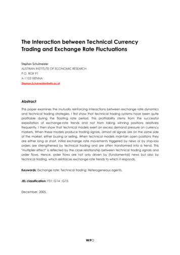
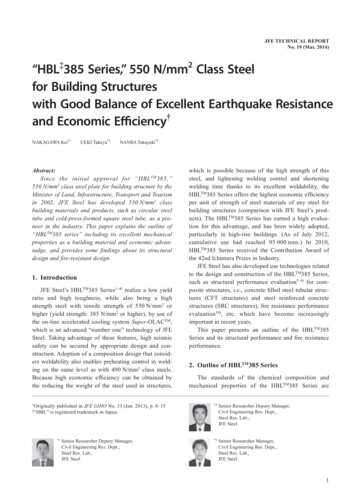
“HBL385 Series,” 550 N/mm2 Class Steel for Building Structures with Good Balance of Excellent Earthquake Resistance and Economic Efficiencyare distributed in the same range as those of CFT columns using conventional 400 and 590 N/mm2 classsteels, showing that the G385 CFT columns have structural performance on the same level as CFT columns ofthose steels.4. Fire Resistance PerformanceIn the revision of Japan’s Building Standards Act inJune 2000, the concept of “performance-based design”was also incorporated in fire resistance design. As aresult of this, it is now possible to adopt various materials and structural work methods in fire resistance designby satisfying performance requirements25).This chapter introduces the results10) of an elevatedtemperature tensile test of HBLTM385, which form thebasic data for resistance performance evaluations.(a) Stress at 1% strainThe elevated temperature tensile test was performedbased on JIS G 0567 “Method of elevated temperaturetensile test for steels and heat-resisting alloys” withII-10 type test pieces (JIS: Japanese Industrial Standards). The steel used was the same grade HBLTM385(specified design strength F 385 N/mm2) in all cases.One charge each was performed with the plate thicknesses of 60 mm, 50 mm, and 45 mm, and two chargeswere performed with the thickness of 19 mm, for a totalof five charges.The test results (average of two test specimens) areshown in Fig. 8 (a) and (b). The horizontal axis in thesefigures is the test temperature T, and the vertical axis is(a) Stress at 1% strain and (b) Tensile strength.Figure 8 (c) shows a comparison of the results of atest with 490 N/mm2 class steel (F 325 N/mm2) forwhich results of this test are shown in the literature25)and the elevated temperature strength evaluation formula for steel materials in the 2000 notification of theMinistry of Construction No. 1433. The vertical axisshows Stress at 1% strain standardized by specifieddesign strength F, and the horizontal axis shows the testtemperature T. From Fig. 8(c), it can be confirmed thatHBLTM385 has high temperature strength propertiessimilar to those of the conventional 490 N/mm2.In addition to the elevated temperature tensile test,JFE Steel has also performed fire resistance tests underload for fireproof coated CFT in the HBLTM385 Series10).5. Conclusion(b) Tensile strength(c) Comparison of stress at 1% strainFig. 8This paper has presented an outline of the HBLTM385Series, which was developed by JFE Steel using stateof-the-art technology, and has described the features ofHBLTM385 products as high strength steel materialswhich provide a combination of low yield ratio, hightoughness, and excellent weldability. Tests have confirmed that structural members utilizing these featuresamply satisfy performance requirements correspondingto the part and shape where the materials are used, andvarious design provisions have been clarified. At present, the HBLTM385 Series products are widely used assteel materials for building structures which secure theseismic safety of those structures while also realizingimproved economic efficiency.All these results were achieved by respondingpromptly to the needs of society for building design andconstruction methods as a pioneer in the development of550 N/mm2 class steels.With safer buildings now demanded following theGreat East Japan Earthquake of March 2011, JFE Steel,together with its customers, will continue to contributeto safe and secure town-building.Results of high-temperature tensile testJFE TECHNICAL REPORT No. 19 (Mar. 2014)7
“HBL385 Series,” 550 N/mm2 Class Steel for Building Structures with Good Balance of Excellent Earthquake Resistance and Economic EfficiencyThe authors wish to take this opportunity to expresstheir sincere appreciation to all those concerned in thelaboratory at Fukuyama University, beginning with Prof.Koichi Minami, for their great assistance in performingthe cyclic shear bending test of CFT.12)References14)1) Hayashi, Kenji; Fujisawa, Seiji; Nakagawa, Ichiro. High Performance 550 MPa Class High Strength Steel Plates for Buildings.JFE Technical Report. 2005, no. 5, p. 53–59.2) Suzuki, Shinichi; Ichimiya, Katsuyuki; Akita, Toshikazu. HighTensile Strength Steel Plates with Excellent HAZ Toughness forShipbuilding. JFE Technical Report. 2005, no. 5, p. 24–29.3) Sueishi, Nobuyuki; Arakawa, Takekazu; Ohmori, Akio; Matui,Tokumi. High Strength and Heavy Wall Thickness Steel Pipes forBuilding Structures. JFE Technical Report. 2009, no. 14, p. 9–15.4) Nakagawa, Kei; Kamura, Hisaya; Hirano, Osamu; Fujisawa,Kazuyoshi; Murakami, Yukio. Experimental study on deformationcapacity of 550N/mm2 class cold press formed square steel pipes.Summaries of Technical Papers of Annual Meeting (AIJ). C-1,Japan, 2008, p. 549–550.5) Fujisawa, Seiji; Fujisawa, Kazuyoshi; Nanba, Takayuki. TheStructural Performance of a SRC Column Fabricated by HighStrength Steel of 550 N/mm2 Grade for Building Frames. JFEGiho. 2005, no. 10, p. 41–50.6) Ueki, Takuya et al. Deformation Capacity of CFT using550N/mm2 Press Column. Summaries of Technical Papers ofAnnual Meeting (AIJ). C-1, Japan, 2008, p. 1119–1120.7) Kinoshita, Tomohiro; Nanba, Takayuki; Ueki, Takuya; Murakami,Yukio; Kamura, Hisaya; Shima, Kunio; Minami, Koichi. Experimental Study on Structural Performance of Concrete Filled Tubes(CFT) using High Strength Steel Pipe Part I. Summaries of Technical Papers of Annual Meeting (AIJ). C-1, Japan, 2009, p. 1213–1214.8) Kamura, Hisaya; Nanba, Takayuki; Kinoshita, Tomohiro; Ueki,Takuya; Murakami, Yukio; Minami, Koichi. Experimental Studyon Structural Performance of Concrete Filled Tubes (CFT) UsingHigh Strength Steel Pipe Part II. Summaries of Technical Papersof Annual Meeting (AIJ). C-1, Japan, 2009, p. 1215–1216.9) Nanba, Takayuki; Kamura, Hisaya; Kinoshita, Tomohiro;Murakami, Yukio; Fujii, Toshiki; Minami, Koichi. ExperimentalStudy on Structural Performance of Concrete Filled Tubes UsingHigh Strength Steel Pipe Part 3. Summaries of Technical Papersof Annual Meeting (AIJ). C-1, Japan, 2011, p. 1183–1184.10) Murakami, Yukio; Kinoshita, Tomohiro; Sakamoto, Yoshihito; I,Hidehiro; Suzuki, Takao. Properties of 550N/mm2 Class Steel atElevated Temperature. Summaries of Technical Papers of AnnualMeeting (AIJ). Fire protection, Japan, 2012, p. 271–272.11) Furuya, Hitoshi et al. Effect of Chemical Compositions on the813)15)16)17)18)19)20)21)22)23)24)25)HAZ Toughness and Its Formulation under Simulated ColumnBeam Connection Welding of Structural Steel for Building. KouKouzou Rombunshuu. Japan, 2001, vol. 8, no. 32, p. 17–32.BCJ et al. “2007 Nenban kenchikubutsu no kouzoukankei gijutsukijun kaisetsusho.” (Japanese)Building Research Institute. Kozai Kurabu. Kyodokenkyu Koukouzoukenchikubutsu no kouzouseinouhyouka shikenhou ni kansuru kenkyu iinkai houkokusho. 2002-04. (Japanese)Kido, Yuuta; Yamada, Satoshi; Kuwamura, Hitoshi; Akiyama,Hiroshi;Kadono, Akio. Stub-column test focused on materialproperties: part 1, 2. Summaries of Technical Papers of AnnualMeeting (AIJ). C, Japan, 1992, p. 1245–1248.Inoue, Teturo; Kuwamura, Hitoshi; Buckling Behavior of BoxSection Stub-column of High-Strength Steel with Low YieldRatio Whose Mechanical Property in Tension has Prastic Flow.Summaries of Technical Papers of Annual Meeting (AIJ). C,Japan, 1990, p. 1359–1360.Kato, Ben; Akiyama, Hiroshi; Suzuki, Hiroyuki. Inelastic LocalBuckling of Steel Circular Tubes under Pure Compression. Transactions of the Architectural Institute of Japan (204). 1973,p. 9–17.Kamba, Teruyasu. Stub Column Test of High-strength CRS SteelColumn with Small Diameter-to-Thickness Ratio. Journal ofstructural and construction engineering (507). 1998, p. 123–129.Nakashima, Takashi; Minoda, Sigeru; Ochi, Kenshi; KurobaneYoshiaki. Load-carrying and deformation capacities of highstrength steel tubes: part 1, Stub-column and tensile coupon tests.Summaries of Technical Papers of Annual Meeting (AIJ). C,Japan, 1990, p. 1487–1488.BCJ et al. “2008 Nenban reikanseikeikakugatakoukan sekkeisekou manual.” 2008. (Japanese)AIJ. Recommendation for Limit State Design of Steel Structures.2002, p. 121–124. (Japanese)Kinoshita, Tomohiro; Murakami, Yukio; Fujisawa, Seiji; Kamura,Hisaya; Ueki, Takuya. Verification for lateral buckling performance of H-shaped beam using 550N/mm2 strength steel. Summaries of Technical Papers of Annual Meeting (AIJ). C-1, Japan,2010, p. 889–890.Hirano, Osamu; Tomori, Koichi; Oki, Koji; Watanabe, Kazuo;Yamaguchi, Tanemi; Kawabe, Soichi; Yasufumi, Sasaki. Relationship between weld layer configuration of NBFW and its strength& toughness. Kou Kouzou Rombunshuu. Japan, 2010, vol. 17,no. 66, p. 1–10.ANUHT. “Konkuri-to juuten koukan CFT zou gijutsu kijun doukaisetsu no unyou oyobi keisanrei nado.” 2005. (Japanese)Mori Koji; Fukumoto Noboru. U. S. -Japan Cooperative Structural Research Project on Composite and Hybrid Structures (CFT9) Shear-Flexural Behavior of Concrete-Filled Steel Tubular Columns Part 3. Summaries of Technical Papers of Annual Meeting(AIJ). C-1, Japan, 1996, p. 1027–1032.AIJ. “Guide Book for Fire-Resistive Performance of StructuralMaterials.” 2009.JFE TECHNICAL REPORT No. 19 (Mar. 2014)
y in a tensile test of the steel used in the speci-men. Figure 2 (a)-(d) show the plastic deformation mag-nifi cation R obtained in the experiment with the results for other steel grades14-19). Plastic deformation magnifi - cation R is obtained by subtracting 1 from the ductility factor μ and is defi ned by the following equation.